1. PURPOSE
2. SCOPE
3. REFERENCE
4. RESPONSIBILITY
5. REFRACTORY WORK PLAN
6. REFRACTORY LINING WORK
7. Ceramic Fiber Material
8. REFRACTORY BRICK WORK
9. QUALITY CONTROL.
10. HEALTH, SAFETY AND ENVIRONMENT {HSE)
11. MATERIALS SAFETY DATA SHEET SHEETS
A. MSDS OF 1260 CERAMIC FIBER BULK
B. MSDS OF 1260 CERAMIC FIBER ROPE
C. MSDS OF ALUMINA FOIL.
D. MISDS OF MOULDABLE FOR VACUUM REPAIR
E. MSDS OF VACUUM FORM OBSERVATION DOOR F. MSDS OF VACUUM FORM TUBE COVER
G. MSDS OF WET BLANKET
H. MSDS OF 1000 CERAMIC FIBER BLANKET
I. MSDS OF 1260 CERAMIC FIBER BLANKET
1.0 PURPOSE
The purpose of this Method statement is to provide guidelines of the requirements for refractory works and installation on Fired Heaters/NHT Reactor Feed Heater at Refinery and plants Project.
2.0 SCOPE
This Method of Statement is prepared to describe the various activities involved and the methodology to be followed by the project team for successful completion of Refractory works of FIRED HEATERS/NHT REACTOR FEED HEATER to ensure that the work is carried out safely and in accordance with Project drawings and specifications.
3.0 REFERENCE
Following specification, code and standard shall be form a part of this procedure
1. SAES-N-100 (REFRACTORY SYSTEMS}
2. SAES-N-110 (INSTALLATION REQUIREMENTS – CASTABLE REFRACTORIES)
3. SAES-N-120 (INSTALLATION REQUIREMENT – EXTREME EROSION RESISTANT REFRTACTORIES)
4. SAES-N-130 (INSTALLATION REQUIREMENT- REFRACTORY BRICKS)
5. SAES-N-140 (INSTALLATION REQUIREMENT- REFRACTORY CERAMIC FIBRE}
6. SATIP-N-110-01 (CASTABLE REFRACTORY INSTALLATION)
7. SATIP-N-120-01 (EXTREME EROSION RESISTANT REFRACTORIES}
8. SATIP-N-130-01 (REFRACTORY SYSTEM- FIRECLAY BRICKS & TILE INSTALLATION)
9. SATIP-N-140-01 (REFRACTORY CERAMIC FIBRE INSTALLATION}
4.0 RESPONSIBILITY
4.1 PROJECT ENGINEER
Control the overall operation of BFIM at site look after the overall construction activities and especially all supervisors, material handling fabrication, erection, rigging, installation, and temporary works relating erection. Ensure that HSE policies for the project are adhered to and that safety inspector does carry out their duties.
4.2 SAFETY INSPECTOR
1. Ensure the HSE policies and procedures are well understood & followed.
2. Shall maintain proper documentation with respect to safety of the project and shall communicate effectively to all personnel.
3. Safety inspector shall convey the importance of safety procedures and the consequences of violating safety procedures.
4. Safety Inspector shall report not only High Potential Near Miss but all near miss to management.
5. Maintain compliance of all the applicable rules & regulations implemented by Saudi Aramco.
6. Provide the necessary training or advice for ensuring a correct safety activity.
4.3 QA/QC INSPECTOR
1. Controlling the overall site QA/QC personals and activities
2. Charging the Inspection and test of all permanent materials, the work performed at site up to code, standards, project specifications, drawings and procedures
3. Maintaining the Quality documents and records
4. Performing inspection the each work as per inspection and test plan at site.
5. Communicating all relative inspection parties such as QA/QC personal.
4.4 SUPERVISOR
1. Supervise foreman, allocated labors to execute the works properly and safely.
2. Check proper equipment and tools to be used for the purpose
3. TSTI Talks will be held by supervisor in charge of the work each new task is started.
4. These meeting shall focus on:
5. Specific Hazard identified.
6. Specific procedure for work at erection work.
7. Specific instructions unique to work at hand.
5.0 REFRACTORY WORK PLAN
5.1 Pre-Shipping Inspection
The refractory material is to be inspected prior to shipment. Inspection certificate shall be kept separately QC files:
6.0 REFRACTORY LINING WORK
6.1 Material Storage
1. All receiving Castable materials will be stored indoor or keeping under shelter protections against direct sunshine and rain. Wooden pallets one or two stages will be used for protecting moisture from ground. The stocking areas should be well ventilation as well.
2. Should materials be transferred out from the stocking areas to the work-fronts, pallets and temporary covering sheets e.g. tarpaulin, plastic, etc. be used for such protection by having some spacers between them. However, care should be taken to withdraw and transport only just enough quantities for application on each day. Should any left-over materials exist and being inconvenience in transporting back to the warehouse, some fastening materials be used for securing the coverings during overnight.
3. The best way for controlling of materials is to have a good planning and locating of the materials in priority of usage/consumption with good documentary control. Additional markings may be needed for easy identifications. These will help in time saving and avoiding mistake in use though the final check at the work-front before mixing is a normal practice.
4. All surplus materials after work completion must be reported and returned to owner.
5. Contractor to provide 3rd party for waste disposal, 3rd party is responsible for collection and transportation of waste. To ensure that waste are properly disposed 3rd party contractor to provide treatment and disposal certificate.
6.2 Water for Mixing
1. Water to be used for mixing with the refractory will be potable water, if not the analysis be made prior to using and to be within the following limits. All surplus materials after work completion must be reported and returned to owner. ARCC to provide 3rd party for waste disposal, 3rd party contractor to provide necessary documents to ensure proper disposal.
Mg2+ less than 300ppm
K+ Na+ less than lS0ppm
Cl- less than S0ppm
Fe3+ less than 300ppm
S04- less than 200ppm
Residue after evaporation at 180°C < 1500 ppm
2. The water and the refractory temperature to be used for mixing with the refractory should have a temperature between 15°C to 25°C. In case of high ambient temperature, broken ice will be used for mixing with the water in a specified sizable container to obtain the temperature within the specified range prior to using for mixing
3. The water container can be either clean tank of 100 to 200 liter capacity with some make-up tank nearby. A portable thermometer whether digital or bulb type be feasible for the purpose but should be accurate enough in the reading range. Also these will be calibrated at the specified period or at least once a year.
4. In order to ensuring of correct amount of water to be used for mixing as per specification requirements, an accurate measuring cup of 5°10 liter capacity be used for metering the water quantity for each mixing batch.
6.3 Checking of Anchor
Before commence of the works, checking of all anchors on the surfaces to be lined for correction according to the specified drawings and the related details, e.g. configuration/profile/type, material, diameter, height, spacing, orientation, defective points, etc. If any discrepancy arises, cooperating with the concerned parties to rectify them to good/correct conditions.
6.4 Installation of Pouring Material
6.4.1 Mixing Machine
A vertical type paddle mixing machine, driven by electric motor, will be used for the casting and pouring method. The speed of the mixer should be 3040rpm. Opening or discharging door under the paddle mixer must be checked and be remedied to good condition that will not let the castable to leak out during filling or mixing in order to ensuring of the mixture consistency. The mixer can handle 3°5 bags for each mixing batch. Quantities of mixers are depending on the work load and the work fronts. No domestic plugs / sockets are permitted.
6.4.2 Forming and Shuttering
For ensuring of good forming and shutter, care should be taken on the following points.
1. Wooden planks and struts for making the form-work should be tough enough to endure the pressure of refractory, normally 69mm thick, depending on the thickness of linings and space to be lined.
2. Well bracing of the form/shuttering for ensuring that no movement and gap be existed and be strong enough before pouring.
3. Surface on the lining sides shall be coated with non-soluble oil or grease for the purpose of water proofing and easy in removal after setting of castable but that oil must not contaminate or causing any effect to the casting.
4. If there is contaminated by oil, dust and etc., it will be cleaned by wetted soft brush and water.
5. Normally, the form size will be about 1,200mm x 1,200mm for each pouring. This is depending on the locations of the expansion joints and the lines of anchor locations as well. So a good planning in dividing the block sizes is necessary before preparing the wooden forms.
6. Formwork will not be removed within 12 hours after pouring; normally it will be removed in 24hrs on the safe i.e. after curing completion
6.4.3 AP test
1. The Applicator shall perform procedure tests to demonstrate his working method, equipment and operators and be passed the Applicator’s Procedure Qualification (APQ) for the installation of the actual lining. An APQ is required for each crew and type of installation.
2. Each team of mixer operators and applicators shall prepare either a standard shape {230mm x 114mm x 62mm minimum dimensions) or a box specimen (280mm x 180mm x 75 mm minimum dimensions) in a hardwood box. The specimen shall be placed by hand in approximately 25mm thick layers.
6.4.4 Installation
Pouring of castable into the forming locations will be carried out as follows.
1. All casting equipment will be settled near to the work pieces to be poured, clearing of obstructions and other work activities that will interfere or affecting to the efficiency/quality of casting work.
2. Necessary safety tools/accessories will be furnished to the working persons and/or protecting to the nearby equipment as a good working practice. Inspection of tools to be carried out monthly by the safety inspector and project specific color coding shall be followed. Any tool found unfit to use shall be removed immediately from service preventing.
3. All tools and mixers must be cleaned prior to start working and re-cleaning of the mixer and the related tools is a must when changing of castable type during the day. Moreover, all tools and equipment must be cleaned up after completion of work on each day.
4. Then cleaning the blocking areas to be free of oil and other foreign matters that will contaminate the castable mixture before pouring by using clean cloth and/or dry compressed
air blowing.
5. After completion of the above, checking as per “Refractory Lining Pre-Check Report be made prior to going further, of which the report will consist the following.
A. Checking of anchor for type, material, diameter, height (first layer step, second layer step), opening angle, spacing, leg orientation, and welding condition.
B. Checking of form-work for type, thickness, spacing, height
C. Surface preparation for denting area, cleanliness, and method of cleaning.
D. Temperature of steel surface, it should be below 32°C
E. Refractory material for type, shelf life, and storage condition.
6. After the above checking and all be acceptable, moving the bags of castable to the resting area or stage nearby to the mixer. Using only good bags of castable, tearing or damaged bags will not be used but put aside for reporting due to lacking of consistency.
7. The screen shall be installed on the top of the mixer and castable bags are opened one by one with e.g. knife on the screen for checking of lump or hardening or aging before pouring into the mixer.
8. After the predetermined bags have been loaded into the mixer, switch on the mixer to turn for 56 turn for mixing the dry castable to a condition of homogeneity.
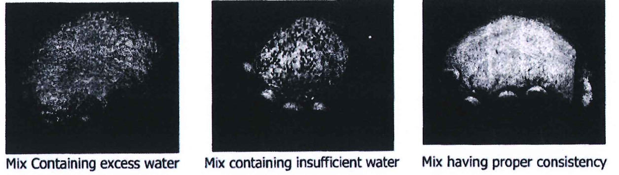
9. Measuring water of 90% of required quantity is poured into the mixer while rotating. After seeing of the mixing condition and gradually poured the balanced quantity of water into the mixer until acquiring the mixture consistency. A ball-on-hand test per each batch is needed for checking the consistency. However mixing for this period should not be last longer than 35 minutes.
10. After seeing the mixture is all-right, open the discharge door below to discharge the well mixture into transferring buckets while the mixer is still running.
11. Then transferring the well mixture will be poured to the prepared lining area by starting from one side until obtaining the required thickness. Then processes pouring to the other and until all the blocking area are fully completed. Scraping and dressing of the lined surface be made as necessary.
12. In case of pouring is interrupted due to some reasons before completing the block, a cut back by steel trowel will be made to the full lining thickness of area before continuing the pouring until fully completed. Also, the left over mixture that last longer than 20 minutes should be discarded.
13. After completion of castable works, recording as per “Work map of castable lining shall be made for traceability further, of which the sheet will consist the following.
A. Location number
B. Material
C. Sample code number
D. Applicator’s name
E. Working date
14. For two (2) layers application, after completion of lining for the first layer and inspection as per ITP (Jl0-F-0401/02/03/04, and J10-F-0200) Rev A, then lining of the second layer is made in the same manner until fully lined. However, before pouring of this second layer, the first layer area of lining has to be wetted prior to pouring of second layer refractory. This is to protect water in the mixture of second layer to protect absorbing by the existing castable lining. Furthermore, overlap the second layer and the first layer is required for at least 100mm apart as below.

6.5 Installation of Gunning Material
6.5.1 Set-up of Gunning Machine
The following figure shows the layout and specifications for castable gunning equipment
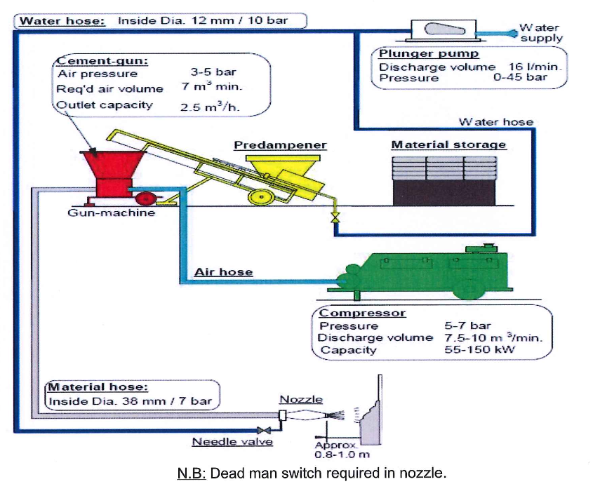
1. A paddle mixer mixing vertically
2. A closed screw conveyor or belt with a small hopper under the outlet of the mixer and the top above the hopper of the gun-machine.
3. The gun-machine preferably with a pressurized chamber system
4. A suitable air compressor equipped with a well-functioning water separator
5. Purpose built hoses (for material as well as water), loop free and as short as practical from gun-machine to work site;
6. A gun-nozzle with sufficient spares
7. A remote radio control between the machine operator and the nozzle-operator
8. Air compressor will be inspected by 3″ party if no valid inspection sticker is available. Whip check will be present on each connect of high pressure hose, if we do not have to procure it.
6.5.2 Expansion Joint
1. Forming and shuttering is not required and impractical due to the high pressure,5-7bar, of gunning
2. The saw cutting should be applied for expansion joint and the size will be about 1.2m x1.2m, wide 3mm, and depth 25mm.
6.5.3 APQ test
1. The Applicator shall perform procedure tests to demonstrate his working method, equipment and operators and be passed the Applicator’s Procedure Qualification (APQ) for the installation of the actual lining. An APQ is required for each crew and type of installation.
2. Each team of mixer and gun machine operators, nozzle-man and helpers shall prepare a panel, approx. 1.5m x 1.5m, provided standard anchoring, V-shape, diameter 6mm, height 100mm, pitch 150mm. Minimum application thickness shall be 120mm. The test panel should be a reflection of the anticipated production job and be inspected as per ITP.

3. Each team shall prepare test specimens by gunning one or more panels sized 500mm x 500mm x 114mm minimum dimensions without anchoring and test specimens shall be tested.
4. The Applicator shall not change the settings for gunning, water quantity and pressure level. Gunning shall continue until the panels are completed and after trimming the panels are left
to set.
5. Before the panels harden it shall be visually examined by Inspector; gentle knocking shall not reveal any air inclusions or voids. Pieces taken from the sample shall show an even distribution of the granulates and shall demonstrate the absence of laminations.
6.5.4 Installation
Gunning of castable into the application locations will be carried out as follows.
1. All gunning equipment will be settled near to the work pieces to be gunned, clearing of obstructions and other work activities that will interfere or affecting to the efficiency/quality of casting work.
2. Necessary safety tools/accessories will be furnished to the working persons and/or protecting to the nearby equipment as a good working practice.
3. All tools and equipments must be cleaned prior to start working and re-cleaning of the equipments and the related tools is a must when changing of castable type during the day. Moreover, all tools and equipment must be cleaned up after completion of work on each day.
4. Then cleaning the blocking areas to be free of oil and other foreign matters that will contaminate the castable mixture before pouring by using clean cloth and/or dry compressed air blowing.
5. After completion of the above, checking as per “Refractory Lining Pre-inspection Report” be made prior to going further, of which the report will consist the following.
A. Checking of anchor for type, material, diameter, height (first layer step, second layer step), opening angle, spacing, leg orientation, and welding condition.
B. Checking of form-work for type, thickness, spacing, height
C. Surface preparation for denting area, cleanliness, and method of cleaning.
D. Temperature of steel surface, it should be below 32°C
E. Refractory material for type, shelf life, and storage condition.
6. After the above checking and all be acceptable, moving the bags of castable to the resting area or stage nearby to the pre-mixer. Using only good bags of castable, tearing or damaged bags will not be used but put aside for reporting due to lacking of consistency. Shall put the plastic tray to prevent the ground contaminant.
7. The screen shall be installed on the top of the per-mixer and castable bags are opened one by one with e.g. knife on the screen for checking of lump or hardening or aging before pouring into the mixer.
8. Then load the quantity of pre-determined material into the pre-mixer and pour the additive material.
9. After the loading the materials, castable and additive materials, switch on the pre-mixer to turn for approximately 2 minutes for pre-mixing the dry castable to a condition of homogeneity.
10. After seeing the pre-mixture is all-right, open the discharge door of mixer below to discharge the well mixture into transferring predampener by a shovel while the mixer is still running.
11. Predamped material shall be mixed by adding 2% of water until it is homogeneous with no lumps for 2 minutes and used within 20 minutes of mixing.
12. The gunning machine is required a constant supply of water and air depending on the distance between the gunning machine and the nozzle, the nozzle size, elevation of working location.
13. When the mixed material is loaded into gun-machine, the operator of gunning machine shall open the control valve of gun-machine for the gunning. The direct communication by radio between the nozzle operator and gun-machine operator is essential.
14. The applicator shall adjust the amount of water properly by the needle valve of nozzle and then apply to the prepared lining area by starting from one side until obtaining the required thickness. The application of lining shall be continuous until the unit or section is completed. When the interruption is expected to extend longer 10-15 minutes, the area not gunned to
the full thickness must be cut out and removed.
15. The gunning nozzle should be held at approximately 90 degrees to the receiving surface and maintained at a distance of approx. lmeter from the surface. The nozzle shall be moved in a small circular motion that reduces the rebound loss and the risk of laminations and gives an equal material structure.
16. It is important that the material be gradually built up to the full thickness over a small area at a time. Progress should be made from bottom to top when gunning concrete on vertical walls, this prevents rebound material dropping down and sticking to the unlined shell and to the anchors below.
17. This is particularly important where a given distance between lining surfaces and process tubes must be respected, or wherever precision of thickness is imperative.
18. Where trimming is required, the surface shall be scraped with a trowel or a steel float or, better, with a special nailed brush as soon as possible after completion of the gunning.
A trowel led smooth surface finish must be avoided.
19. During the work of the above, recording as per “Gunning control log sheet shall be made for tracing further, of which the sheet will consist the following.
A. Applied material, material batch no.
B. Mixing condition (water, material, temperature and etc.)
20. After completion of castable works, recording as per “Work map of castable lining” shall be made for traceability further, of which the sheet will consist the following.
A. Location number
B. Material
C. Sample code number
D. Applicator’s name
E. Working date
21. For two (2) layers application, after completion of lining for the first layer and inspection as per ITP, then lining of the second layer, if any, is made in the same manner until fully lined. However, before gunning of this second layer, the first layer area of lining has to be wetted prior to gunning of second layer refractory. This is to protect water in the mixture being absorbed by the existing castable lining.
6.6 Sampling and Testing during Installation
1. The Applicator shall prepare a number of sample (panels) using the sample refractory materials being installed. The minimum number of samples is the following

2. Samples are either a standard shape (230mm x 114mm x 62mm minimum dimensions) or a box specimen (280mm x 180mm x 75 mm minimum dimensions) in a hardwood box.
3. Each sample shall be clearly marked with the cord number for that day shift/crew and for sequence of production.
4. Each code shall be unique and traceable to the locations where refractory has been applied by that crew during that shift
5. The samples are regularly delivered for test to the test laboratory and Test specimens shall be cut from the sample at the laboratory after being prepared, cured and air dried at the site
6. For the each sample, the following properties shall be tested
A. Bulk density
B. Apparent porosity
C. Water content
D. Cold crushing strength dried at 110°C
E. Permanent linear change fired at the appropriate temperature.
7. The acceptance criteria for these tests shall be as bellows:

6.7 Curing and Drying
1. After completing pouring/casting of each block, the lining surface has to be checked with a finger rubbing on the surface until showing no refractory adhering to the finger. This is about one hour after pouring. The blanket will be covered and then water mist will be sprayed at an interval, this depends on the ambient temperature and humidity content on that day.
2. Curing is normally carried out for the first 24 hours after application. Then the coverings must be opened to let the surfaces to be dried freely with well ventilation. Since, for insulating castable.
3. During the curing, the temperature shall be controlled to maintain below 32 °C and recorded per 2 hours a day time.
6.8 lining Inspection
Inspection must be visual and audio (by using a test hammer) and is carried out after both normal air drying and firing dry-out.
6.8.1 Visual Inspection
1. If cracks are found, a decision becomes necessary to decide whether they are likely to adversely affect the normal operation of the unit.
2. Repairs should be made to areas containing cracks each wider that 3mm. as well as complete areas having random cracks up to about 3mm. width but which are within 300mm. of each other.
3. The size and positions of expansion joints must be inspected and confirmed correct.
6.8.2 Audio Inspection (Hammer Test)
1. It involves the practice of striking the lining over its entire area with a ball point machinist hammer having a recommended weight of 450 grams.
2. The lining is struck according to various but specified grid patterns. For example a roof might be struck at 600mm. intervals while side walls and floor at 900mm. intervals.
3. When struck with a test hammer, the sounds emitted are more clearly distinguishable in fired linings rather that in those only naturally air dried.
4. For multi-layer linings, the hammer test should be conducted on each layer; after the curing of the back-up layer(s). If sounding indicates the presence of an abnormality in an area greater than 150mm. x 150mm, this area must be repaired.
5. Also all sort or dry fill areas that reduce the effective lining thickness by more than 1/4 of the original thickness or if more than 13mm. deep must be repaired ..
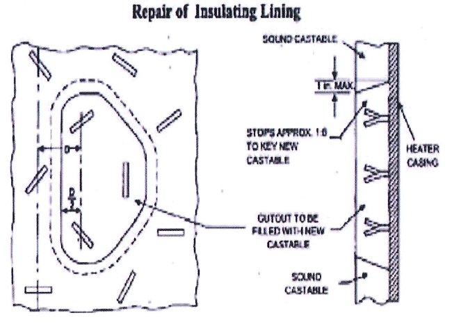
6.9 Repair of Lining
1. If inspection reveals defective areas as previously defined greater than 150mm. x 150mm, the full thickness of the defective concrete layer must be removed for a minimum area that includes 3-4 anchors.
2. Care must be taken in the removal of the faulty material that the surrounding of sound lining is not damaged and neither, if it is presents the back-up lining.
3. The area being repaired should be cleaned of all loose concrete and debris and the adjacent sound material thoroughly wetted before any new concrete is installed.
4. Only the same concrete is originally employed should be used for replacement and particularly in large areas, the same installation method as was originally used is required.
5. After repair work of castable lining, Crack and Repair Report should be recorded.
7.0 Refractory Application Procedure (Ceramic Fiber Material)
7.0.1 Application
A. Stud application shall be done by the contractor.
B. After the studs have been welded in place, the backup insulation is impaled over the studs. In order to facilitate temporary retention of the backup insulation, especially on a roof, mild steel speed clips are installed over the studs. Clips shall be installed as per drawing.
C. A 203 mm — 305 mm (8″-12″) length of 19 mm (3/4″) or 25.4 mm {1″) I.D. Pipe is useful for pressing the speed clips on the studs. If cup locks are to be used as retainers, speed clips cannot be used within 76 mm (3″) of the hot face since they will prevent proper installation of the cup locks. In this case, twine or rubber bands can be stretched across the studs as temporary retainers and left in place.
D. When installing successive layer of material, care must be taken to insure that all joints are staggered by at least 101 mm (4″) and that the exposed hot face layer is properly positioned on the studs.
8.0 REFRACTORY BRICK WORK
8.1 Material Storage
8.1.1.1 All receiving Brick materials will be stored indoor or keeping under shelter protections against direct sunshine and rain. Wooden pallets one or two stages will be used for protecting moisture from ground. The stocking areas should be well ventilation as well.
8.1.1.2 Should materials be transferred out from the stocking areas to the work-fronts, pallets and temporary covering sheets e.g. tarpaulin, plastic, etc. be used for such protection by having some spacers between them.
8.1.1.3 AI surplus materials after work completion must be reported to the Contractor for taking further actions. Since discarding of scraps or unused materials will cause expenses under the government environmental regulations
8.2 Brick lining (1 layer required for Heaters)
8.2.1.1 Measure, check and compare with the installation drawings before start of work; for example piece amount (number) of layers between consoles, expansion joints, and anchor distribution.
8.2.1.2 The bricks must be kept clean, specifically the expansion joints
8.2.1.3 Refractory bricks must be laid horizontally unless the design of the furnace or plant requires inclined positions or inclinations.
8.2.1.4 The bricks must be installed and aligned very precisely to avoid unnecessary cutting work and to obtain uniform joint thickness
8.2.1.5 For the joint parts to burners of heaters, the castable material shall be filled up as per drawing
8.2.1.6 If the bricks are cut, the given joint thickness must be also be considered at the cut edge
9.0 QUALITY CONTROL
1. BFIM/ ARCC Inspector will be assigned to attend quality control and quality assurance requirements of the works
2. BFIM/ARCC Inspector shall monitor every phase of activities to ensure quality is implemented accordingly and conduct mark-up sample.
3. Upon completion the contractor jointly with client shall conduct a thickness inspection using a needle penetration gauge to ensure conformance with approved thickness. The approved thickness may be considered the minimum thickness of the individual thickness reading measured.
4. QA/QC Inspector shall ensure that the inspections are completed in accordance with the requirements. He will conduct random inspections as per the requirements to verify compliance with the specification and design drawings.
5. The SB technical team and construction team shall ensure that the latest revisions of approved drawings/ documents are used on site.
6. Any discrepancies found during an inspection will be immediately communicated to the Manager/Engineer for rectification and compliance with specified requirements. Discrepancies shall be rectified prior to the Engineer’s inspection.
10. Health, Safety and Environmental (HSE)
1. Refractory materials are chemical composites and the mixtures can contain or form hazardous chemical components. These can occur in freshly produced mixtures as well as in use and during removal of aged material.
2. All refractory lining work shall be followed the MSDS provided by Vendor.
3. Approved Work Permit shall be obtained prior to start any Refractory Lining Works.
4. The Refractory supervisor with the assistance of the safety department will carry-out a safety risk assessment identifying the actual hazard and possible precaution to be taken to eliminate or lessen the risk prior to start of any activities.
5. The necessary manpower inclusive of Supervisory Staff, tools, equipment, materials
and other resources required must be made available and ready to use.
6. Workers shall always wear their Personnel Protective Equipment (PPE’s) required for the work.
7. Certified Permit Receiver, in case of any confined space work a hole watcher trained by Main Contractor’s Training Department and Work in-charge should be at worksite during the execution of the work. All entrants require training.
8. Tools to be secured with a restrainer string at open areas during activities to prevent possibility of injury due to falling objects.
9. After the day works a good housekeeping shall be maintained.
10. Contractor’s to provide safety fence at level to be agreed mutually with BFIM.
11. Contractor’s to provide safety lifeline at every prior to commence the installation of the certain levels.
12. Contractor’s Safety Officer will ensure the compliance and implementation of site safety requirements by workers and staff.
13. Hard hats, coveralls, safety boots, safety belts and harnesses for installation, welder goggles and hand gloves, safety glasses, reflective vests and dust masks are mandatory.
14. All works shall be performed in accordance with the Engineer’s HSE Manual and Contractor’s HSE Plan and Procedures.
15. Senior Site Supervisor will ensure that Mandatory Personal Protective Equipment is worn by site personnel at all times within the designated construction areas.
16. Prior to commencement of any activity, all operatives will be given in a general site safety induction by HSE Personnel; the Site Supervisors will also conduct Tool Box talks and method statement briefings to the personnel involved in operation. All staff will undergo contractor’s induction training.
17. General PPE is mandatory for all personnel will consist of safety boots or shoes, safety helmet, safety gloves, HI-VI2 vest or shirt and overalls (for workers). Other PPE requirements will be determined by Risk Assessment as the work proceeds and other hazards are anticipated i.e. working at height/ or at the leading edge of a structure.
18. Lifting equipment will have a valid test certificates from a third party agency or manufacturer.
19. Where required rigid edge protection will be provided, if it is not practicable to provide edge protection, safety harnesses will be worn fixed to suitable anchor points.
20. In case of fire/ emergency evacuate the work area to the designated assembly points.
21. Field safety inspector shall consistently monitor and ensure compliance on confined space entry requirements, heat stress management, road traffic safety, emergency response plan, fall prevention, waste management including entire welfares & housekeeping requirements.
22. Ensure that personnel comply with all safety rules and requirements in the conduct off types of scaffolding erection activities performed in the project. Ensure that personnel shall apply the method statement that has been approved by the SAUDI ARAMCO.
23. Ensure the works permit procedure and JSA being adhered, assuring the inspection system being observed. Only competent person must inspect the ladders and scaffold assemblies.