1 SCOPE ………………………………………………………………………………………….. 3
2 CODES, STANDARDS, CRITERIA, DEFINITIONS ……………………………… 4
3 DESIGN REQUIREMENTS ………………………………………………………………. 8
4 RELIEF VALVE – SIZING ……………………………………………………………….. 10
5 RELIEF VALVE – SELECTION ………………………………………………………… 11
6 RELIEF VALVE – MATERIAL SPECIFICATION …………………………………. 12
7 SHOP TESTING AND INSPECTION………………………………………………… 13
8 STORAGE OF PSV ……………………………………………………………………….. 14
9 FIELD TESTING AND INSPECTION REQUIREMENT ……………………….. 14
10 SELLER DOCUMENTATION REQUIREMENT ………………………………. 15
1 SCOPE
This standard provides a comprehensive standard for sizing, design, purchase, testing,
inspection, installation, and documentation requirements for Relief Valves.
1.2 Definitions
1.2.1 Owner: and/or designated representative
1.2.2 Contractor: A company responsible for Engineering/Procurement and/or
Construction
1.2.3 Seller: Supplier of services, equipment fabrication or materials
1.3 Document Order of Precedence
In the event of conflict between purchase documents, the order of precedence will be
as follows:
a. Purchase order
b.
Datasheets and drawings
c. Project Specifications
d. Pertinent Specifications
e. Secondary Standards or codes referenced in above.
1.4 Tagging and Marking
1.4.1 Each relief valve shall be fitted with a permanently attached stainless steel
nameplate; indicating contractor’s tag number, purchase order number, and
service description in addition to the code required nameplate marking. The
nameplate shall conform to API standard 526
1.4.2 Following shall be included as minimum on manufacturer’s standard
nameplate.
a. Manufacturer’s name and/or trade mark
b. Manufacturer model number.
c. Material
d.
Inlet and Outlet size
e. Set Pressure
f.
Cold Differential Test Pressure
g. Spring Number
Springs consisting of 1/4 inch wire diameter and larger shall be permanently
stamped with a symbol identifying the manufacturer, material, and size and
pressure/temperature range. Spring consisting of less than 1/4″ wire
diameter shall have a metal tag with the data fastened/attached to the spring.
2 CODES, STANDARDS, CRITERIA, DEFINITIONS
The following Codes, Standards, and Specifications (per latest revision or addendum) shall
apply as referenced in this document:
2.1 Codes and Standards
2.1.1 American Petroleum Institute (API)
API RP-520: Design and Installation of Pressure Relieving Systems in
API RP-521: Guide for Pressure Relief and Depressurizing Systems
API STD-526: Flanged Steel Relief Valves
API STD-527: Commercial Seat Tightness of Relief Valves with Metal to
Metal Seats
API STD – 620: Design and Construction of Large, Welded, Low Pressure
API STD-2000: Venting Atmospheric and Low Pressure Storage Tanks
2.1.2 American Society of Mechanical Engineers (ASME)
ASME Section I: Construction of Power Boiler
ASME Section VIII: Construction of Pressure Vessel
2.1.3 National Association Corrosion Engineers International (NACE)
NACE-MR-01-75: Material requirements, sulfide stress cracking
resistance-metallic material for oilfield equipment.
2.1.4 American National Standards Institute (ANSI)
ANSI B16.5: Standard for Bolts and Nuts
2.1.5 American Society of Testing Materials (ASTM) ASTM B16.47: Standard for
Material of Construction for Storage Tanks
2.1.6 SABIC ENGINEERING STANDARDS
G24-E01 & S20-G01 Plant and Equipment Noise Control
P01-E01
Design Conditions and Basis for Pressure Piping
P14-T03
Specification for Piping, Tractability and Certification
Z01-G07
Specification for Shop Preparation of Equipment and
Materials for Shipment
2.2 Criteria
Described below is a short summary of applicable code requirements and
recommended practices. Refer to individual codes or publications for detail
information and interpretation.
The American Petroleum Institute (API) publishes recommended practices. These
are not codes but in many respects serve as equivalents to the codes.
The API documents contain guidelines and are, therefore, only intended to
supplement information set forth in the Pressure Vessel Section VIII of ASME Boiler
and Pressure Code. Division 1 of this code stipulates that “All pressure vessels within
the scope of this Division shall be protected with protection devices in accordance
with requirements of UG-125 through UG136.”
Applicable codes for the design and installation of over-pressure protection systems
are:
2.2.1 ASME Section I – Criteria / Guidelines
2.2.1.1 Boiler: At least one Relief valve (more with large capacity boilers)
2.2.1.2 Economizer: At least one Relief valves if it can be blocked-in
2.2.1.3 Superheater: At least one Relief valve
2.2.1.4 Reheater: At least one Relief valve (Reheater Outlet to have one)
2.2.1.5 Rupture Disks: Not permitted
2.2.1.6 Relief valves shall be sized for the rated capacity of the boiler.
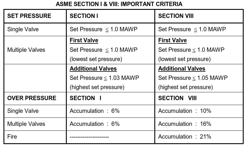
Pressure rise shall not exceed 6% of MAWP.
2.2.1.7 At least one relief valves shall be set at or below MAWP. Pressure
setting of the additional valves shall not exceed 103% of MAWP.
2.2.1.8 If multiple relief valves are used, the difference between the highest
and lowest set pressures shall not exceed 10% of the highest one.
2.2.1.9 Isolation valves shall not be installed upstream or downstream of
relief valves.
2.2.2 ASME Section VIII -Criteria / Guidelines
2.2.2.1 At least one relief valve shall be set at or below MAWP. Pressure
setting of the additional valves shall not exceed 105% of MAWP.
2.2.2.2 Relief valves located at the top of a vessel shall be set at the MAWP
of that section of the vessel.
2.2.2.3 For liquid filled vessels, consideration for liquid static head shall be
given when set pressures are selected.
2.2.2.4 Set pressure tolerance shall not exceed ± 0.14 Bar for pressures up
to and including 5 Bar (gage), and ± 3% for pressures higher than 5
Bar (gage).
2.2.2.5 Set pressure shall be compensated for a variation between actual
relieving and initial setting temperature. Adjustments are to be
recommended by the pressure relief valve manufacturer.
ASME SECTION I & VIII: IMPORTANT CRITERIA
2.3 Definitions
Following is a partial list of various terms. Refer to API-RP-520 and applicable ASME
Section I and VIII for a more complete list of items.
2.3.1 Accumulation: The pressure increase over the maximum allowable working
pressure (MAWP) of the pressure vessel allowed during a discharge through
the pressure relief valve; it is expressed as a percentage of the MAWP or in
gage pressure. Maximum allowable accumulations are established by
applicable codes for emergencies, operating and fire emergencies.
2.3.2 BackPressure – Backpressure is the static pressure existing at the outlet of a
relief valve due to pressure in the discharge system. It is the sum of the
superimposed and built-up backpressure
2.3.3 Superimposed BackPressure – Superimposed backpressure is the static
pressure exists at the outlet of a relief valve at the time the device is required
to operate. It is the result of pressure in the discharge system from other
sources and may be constant or variable.
2.3.4 Built-up BackPressure: The pressure, which develops at the valve outlet as a
result of flow, after the relief valve opens. This type of backpressure will
depend on the type of discharge system installed and will determine whether
a conventional or balanced bellows type relief valve is required for vapor
relief.
2.3.5 Burst Pressure: The pressure rating of a rupture disk at the specified
temperature is the value of the upstream static pressure minus the value of
the downstream static pressure just prior to when the disk bursts. When the
downstream pressure is atmospheric, the burst pressure is the upstream
static gage pressure.
2.3.6 Cold Differential Test Pressure (CDTP): The pressure at which a pressure
relief valve is adjusted to open on the test stand. The cold differential test
pressure includes corrections for the service conditions of backpressure or
temperature or both.
2.3.7 Blowdown: The difference between the set pressure and the reseating
pressure of the relief valve expressed as a percentage of the set pressure or
in pressure units.
2.3.8 Closing Pressure: Closing pressure is the value of decreasing inlet static
pressure at which the valve disk re-establishes contact with the seat or at
which lift becomes zero.
2.3.9 Maximum Allowable Working Pressure (MAWP): The maximum gage
pressure permissible at the top of a completed vessel in its operating position
for a designated temperature.
2.3.10 Maximum Relieving Pressure: The pressure at which the relief valve reaches
its full capacity. It is equal to set pressure plus over pressure.
2.3.11 Over Pressure: The pressure increase above the set pressure of the relieving
device allowed to achieve rated flow.
2.3.12 Set Pressure: The inlet gage pressure, at which the pressure relief valve has
been adjusted to open under service conditions. For single pressure relief
valves this pressure shall be equal to or lower than the MAWP of the
equipment which it protects.
2.3.13 Rupture Disk Device: A non-reclosing pressure relief device actuated by
static differential pressure between the inlet and outlet of the device and
designed to function by the bursting of a rupture disk. A rupture disk device
includes a rupture disk and a rupture disk holder.
2.3.13.1 A rupture disk is a pressure containing, pressure and temperature
sensitive element of a rupture disk device.
2.3.13.2 A rupture disk holder is the structure, which encloses and clamps
the rupture disk in position. (Some disks are designed to be installed
between standard flanges without holders.)
2.3.13.3 A non-fragmenting rupture disk is a rupture disk designed and
manufactured to be installed upstream of other piping components,
such as safety relief valves, and will not impair the function of those
components when the disk ruptures.
2.3.14 Conventional Pressure Relief Valve: A spring-loaded pressure relief device
whose operational characteristics are directly affected by changes in the
backpressure.
2.3.15 Balanced-Bellows Pressure Relief Valve: A relief device that incorporates a
bellows for minimizing the effect of back pressure on the performance
characteristics, i.e. opening pressure, closing pressure, lift and relieving
capacity.
2.3.16 Pilot-Operated Relief Valve: A relief valve in which the major relief device is
controlled by a self-actuated auxiliary pressure relief valve. This auxiliary
valve may actuate the main valve either directly or remotely by static
pressure in the protected system.
2.3.17 Pressure Relief Valve A spring-loaded, pressure-relieving device which is
actuated by the upstream static pressure and which opens in proportion to
the pressure increase to open and relieve excess pressure and to reclose
and prevent the further flow of fluid after normal conditions have been
restored. It is primarily used for liquid service.
2.3.18 Pressure Safety-Relief Valve A spring-loaded, pressure-relieving device,
which opens either by rapid pop action or proportional to the pressure
increase over the opening pressure. It may be used for either compressible
or incompressible fluids depending on design, adjustment or application.
2.3.19 Vacuum Relief Device: It is designed to admit fluid to prevent an internal
vacuum or excessive external pressure. It protects a pressure vessel or a
tank from collapsing when the internal pressure drops below the external
pressure (usually ambient air pressure). This could happen during a normal
operation (like pump-out or steam-out), during an abnormal operation (like a
loss of heating medium to the vessel), or weather fluctuations (like a sudden
cooling or condensation of internal vapors).
2.4 This Specification contains selected requirements from the following SABIC
Engineering Standards.
S03-E01 Pressure Relief
S04-E01 Safety Consideration for Plant Layout
3 DESIGN REQUIREMENTS
3.1 General
3.1.1 Body castings shall meet the respective ASTM B16.47 standards for the
materials of construction specified on the Instrument Datasheets.
3.1.2 Quality Assurance Certificate that the castings meet these standards shall
remain with the Seller.
3.1.3 All relief valves shall have flanged end connections unless piping line class
specifications permit threaded connection. Flange rating, facing and finish
shall be specified on the datasheets in accordance with piping line class
specifications.
3.1.4 Flange relief valve shall have enclosed spring, bolted bonnet, and screwed
cap and full one piece nozzle. Minimum requirement for inlet flange shall be
150 RF.
3.1.5 Thermal expansion relief valve shall have screwed bonnet and modified
nozzle. Steel valve shall be 3/4″x 1″ and bronze valve shall be 3/4″x3/4″.
3.1.6 2 1/2 flanges shall not be used.
3.1.7 Relief valves with vented bonnets shall be equipped with bug screen.
3.1.8 Refer to Z01-G07 for shop preparation and shipment of material.
3.2 Design
3.2.1 When a rupture disk and/or a block valve is installed on the relief valve inlet,
the inlet pressure loss shall account for these items.
3.2.2 Total inlet pressure loss from bottom of the relief valve inlet flange to pipe or
vessel connection, for relief valve, Rated Capacity based on “the effective
orifice discharge area” with 10% overpressure shall not exceed 3% of relief
valve set pressure whether in liquid, vapor or two-phase service.
3.2.3 Isolation block valve shall be in a car-seal-open position and should have a
bore area equal or greater than the relief valve inlet and outlet.
3.2.4 Isolation block valves shall not be provided when relief valve discharge is
routed to the atmosphere.
3.3 Bonnet and pilot vent
3.3.1 A bonnet or pilot vent shall be piped to safe location and designed to avoid
plugging caused by ice or insects.
3.3.2 Bonnet of a conventional relief valve shall not be vented to atmosphere if it is
in a hazardous service.
3.3.3 Bonnet of a balanced-bellows relief valve shall always be vented to
atmosphere to ensure proper operation. Vent shall be routed to a safe
location if it is in a hazardous service.
3.4 Code Requirement:
Relief valve shall be provided for all pressure vessels and piping in accordance with
applicable ASME codes and regulations governing the design, fabrication, and
installation of pressure vessels. All relief valves shall be stamped with applicable
code stamp (ASME Section I or VIII).
3.5 Relief valve Types:
In general, relief valves shall be standard disc and nozzle type, with guided-stem and
disc holder, closed bonnet and screwed cap (except thermal relief, pilot-operated,
ASME Section I and VIII steam relief valves). Conventional relief valves shall be used
when the header backpressure does not adversely affect either the relieving pressure
or the valve operation. Otherwise, balanced-bellows type valves or pilot-operated
relief valves may be specified.
3.6 Double Jeopardy:
Simultaneous occurrence of two or more unrelated contingencies that could result in
an overpressure shall not be considered in the design. However, it shall be used for
determining superimposed backpressure on relieving devices.
4 RELIEF VALVE – SIZING
This section describes the methods for selecting and sizing relief valves based on API
Recommended Practices, API-RP-520, API-RP-521and ASME. The equations used by
different Sellers are similar to basic API Methods and ASME except that formula their
nomenclature, correction factors and equations may vary slightly. All initial, generic
calculations shall be modified with specific Seller methods, correction factors and coefficients.
If a relief valve Seller is pre-selected, his specific methods and/or computer programs may be
used at an early stage.
Number of relieving devices is a function of the total relieving area required and the largest
relieving area available commercially.
4.1 General
4.1.1 Seller shall notify Contractor of any conflict of this specification with any other
documents or datasheets to resolve the inconsistency.
4.1.2 Seller shall check all sizing of valve in accordance with the information given
on the datasheets; any inadequacies in the Contractor’s specification shall be
quoted as an “alternate”.
4.1.3 “O” ring soft sheats shall only be used when specified on the Contractor’s
datasheets.
4.1.4 Seller shall indicate “Cold differential test pressure” figures on the
datasheets, Seller print and nameplates.
4.1.5 SI units shall be used however, English units shall be used to define pipe and
flange sizes as per ASME standards.
Following units shall be used:
Temperature °C
Pressure Bar
Flow rate Kg/h
Flow rate (volume) m3/h
Density Kg/m3
4.2 Specific Issues
4.2.1 Two-Phase Liquid/Vapor Relief: A saturated liquid or a homogeneous mixedphase
fluid
will
produce
vapors
during
a
depressurization
at
the
relief
valve,
which
would impact its performance. Sizing method shall be per API -520
Appendix D: Sizing for two-phase liquids /vapor.
4.2.2 Relief valve Back Pressure: After a specific relief valve is selected, it should
be analyzed for the backpressure and its capacity should be adjusted
appropriately. A balanced-bellows relief valve would minimize the effect of
flashed vapors on its capacity.
4.2.3 Sizing for Fire: Permissible accumulation during an external fire is same
regardless of number of relief valves used for protection.
Fired Pressure Vessel or Boiler (ASME Sect I): Accumulation = 6% MAWP
Unfired Pressure Vessel (ASME Sect VIII): Accumulation = 21% MAWP
5 RELIEF VALVE – SELECTION
5.1 Conventional relief valve
Conventional relief valves shall not be used if the built-up backpressure exceeds 10%
of the set 1 pressure. Balance bellows relief valves shall be considered.
5.2 Balanced Bellows Relief Valve
It is common to use a built-up back pressure up to 30% of the set pressure for a
balanced-bellows design; any higher Backpressure shall be used with caution as well
as, the valve manufacturer shall be consulted. The capacity of the valve and the
maximum allowable back pressure on the bellows shall be verified with the
manufacturer
5.3 Pilot-Operated relief Valve
5.3.1 This is a more complex design with high maintenance requirements. A selfactuated
auxiliary pressure relief valve controls the major relief device
directly or remotely. This setup gives a tight shutoff even with a low operating
margin like 5%.
5.3.2 Pilot operated relief valves shall be used when the built-up backpressure or
the variable superimposed backpressure is expected to exceed 50 percent of
the set pressure.
5.3.3 Pilot sensor and auxiliary valve with their narrow passages are not
compatible with fouling, viscous or polymerizing services.
5.4 Rupture Disk
5.4.1 A rupture disk assembly consists of thin diaphragms usually held between a
special set of flanges designed to hold the disk and enable it to be used as a
pressure-relieving device. Once used, rupture disks leave the flow path open
till it is fixed. Rupture disks shall be purchased with a tight tolerance and a
minimal burst-pressure range.
5.4.2 Only non-fragmenting rupture disks shall be used in series upstream of a
pressure relief valve.
5.4.3 Application of rupture disks shall be minimized, and shall be approved by
OWNER.
5.4.4 Sealing Device: Rupture disks are used to protect internals of a relief valves
from a corrosive, viscous, dirty or polymerizing service.
5.4.5 Whenever a rupture disk is installed under a relief valve, the relief capacity
shall be derated as required by the latest ASME code. A pressure gauge
shall be installed between the two devices to indicate a burst Disk.
5.4.6 Large Relief Area: Rupture disks shall be considered for very large relief
areas required by silos storage bins, etc.
5.4.7 Quick Response: Rupture disks shall be considered for quicker response
during a rapid pressure build-up like runaway chemical reaction, explosion,
inertial impact during an exchanger tube rupture, etc.
5.4.8 Rupture disk sizing shall be based on the total pressure drop required as per
the latest ASME Codes UG-127a2 and shall not be orifice sizing method.
5.5 Rupture Pins
Rupture pins shall not be used without prior written approval from the Owner. They
shall comply with the requirements of ASME SEC VIII D1 AB and ASME SEC VIII D1
BB, Paragraph UG-127-C. When installed upstream of a relief valve, a “balanced”
rupture pin assembly shall be used so that any pressure trapped between the rupture
pin and the pressure relief valve will not affect the opening pressure of the rupture
pin.
5.6 Venting and Breathing for Tanks
Venting and breathing equipment for low pressure above ground storage tanks at
less than 1.03 Bar (gage) shall be sized as per API Standard 2000, section one (1)
through three (3) or API Standard 620 Section 6.
6 RELIEF VALVE – MATERIAL SPECIFICATION
Any relief valve with cast iron body or parts shall not be acceptable. All parts and body shall
be resistant to the brittle fracture at the discharge temperature. None of the components shall
contain asbestos or asbestos-bearing material.
6.1 Body
The relief valve body material shall be suitable to the pressure, temperature and
process fluid under which the valve will operate. The body material shall not be
specified for relieving conditions (i. g., relief temperature during a fire). For flanged
steel relief valves refer to API Standard 526.
6.2 Spring
Relief valve springs shall be suitable to the maximum normal operating temperature.
Springs material shall not be based on maximum relieving temperature unless the
relieving temperature exceeds the rated spring temperature by 100°C. All springs
shall be stamped or permanently marked by the manufacturer with an identification
number.
6.3 Bellows
Minimum bellows material shall be stainless steel unless service conditions require
otherwise. Maximum backpressure required by the relief system shall be less than
the pressure rating of the bellows.
6.4 Bonnet
Bonnet shall have the same material as the relief valve body.
6.5 Nozzle Minimum nozzle material shall be stainless steel unless service conditions
require otherwise.
6.6 Bolting
Bolting material shall conform to ANSI B16.5 for the body material used. Bolts, studs
and nuts shall not be cadmium plated or zinc coated.
6.7 Seat
Metal-to-metal seated relief valves shall conform to API Standard-527 for commercial
tightness. Soft seat shall not be used without written approval from the Owner.
6.8
Lifting Lever
Lifting lever shall not be used unless required by Code. If required, lifting levers shall
be provided as below, Relief valve without Bellows: Packed Lifting Lever Relief valve
with Bellows: Plain Lifting Lever Relief valve in Air Service: Plain Lifting Lever
6.9 Cap A cap shall be specified with a means of inserting a sealing wire to prevent its
removal. Relief valve without Lifting Lever: Screwed Cap Relief valve with Plain
Lifting Lever: Plain Cap (with set screws) Relief valve with Packed Lifting Lever:
Bolted Cap
6.10 Other Parts
6.10.1 Spring retaining washers and set pressure-adjusting nuts shall be of nongalling
materials
consistent
with
the
spring
material.
6.10.2
Rupture disk, disk holder and spindle shall be constructed of stainless steel
unless service conditions require otherwise.
6.11 Trim – Sour Service Body and trim material shall be specified in accordance with
NACE Standard MR-01-75.
6.12 Trim – Steam Service
6.12.1 Any safety relief valve (ASME Section I) or pressure relief valve (ASME
Section VIII) in steam service shall have a thermally stable disk if the valve
set pressure exceeds 20 Bar (gage) or operating temperature exceeds
260°C.
6.12.2 Copper bearing alloys are permitted in ASME Section I steam services only if
they are part of a manufacturer’s standard construction.
7 SHOP TESTING AND INSPECTION
7.1 General requirements for inspection and testing shall be as per the Contractor’s
documents included with the PST’s purchase requisition. As a minimum, the following
items shall be performed:
a. Material test Certificate
b.
Non-destructive examination
c. Visual inspection
d.
Dimensional measurement
e. Hydrostatic test
f.
Seat leakage test
g. Performance test
h. Pressure set test
i.
Alloy verification
j.
Assembly Inspection
k. Piping Material Inspection per Specification P14-T03
7.2 Pressure relief valve bodies shall be pressure-tested with air or steam in the Seller’s
shop before set pressure and leakage tests are conducted. The valve shall be tested
after assembly with a gage in place. The gag shall be removed prior to pressure and
leakage tests. The valve body shall be tested as follows:
7.2.1 Inlet side shall be tested at 1.5 times the specified set pressure.
7.2.2 Outlet side shall be tested at 1.5 times the maximum allowable backpressure
specified by the seller for casting integrity.
7.2.3 Outlet shall be tested at minimum pressure of 3.45 Bar (gage) for soundness
of mating parts.
7.2.4 All Pressure relief valves shall be tested for set pressure (cold differential test
pressure) and leakage in the Seller’s shop.
7.3 Seller shall inform the Contractor a minimum of ten (10) days before witnessed test
are to be performed
7.4 All relief valves shall be furnished with extended spindles to allow testing in place.
7.5 Relief valves shall not be gagged to permit hydrostatic testing of equipment or piping.
Blinds shall be installed as required.
8 STORAGE OF PSV
8.1 Relief valves upstream and downstream connections shall be closed with PVC
covers and master tagged with regards to valve size.
8.2 All relief valves shall be stored in vertical position not directly in contact with sand.
9 FIELD TESTING AND INSPECTION REQUIREMENT
9.1 Responsibility for re-testing and recertification of relief valves before final installation
shall be included in Contractor’s scope of work and shall be performed at site.
Owner shall witness retesting and certification.
9.2 Careful handling of each relief valve must be exercised to assure that the valve
settings are not disturbed prior to or during final installation.
10 SELLER DOCUMENTATION REQUIREMENT
Relief valve Seller shall supply following documents:
a.
Dimensional drawing with parts identification
b. Spring set pressure range
c. Spare parts lists
d.
Installation and handling instructions
e. Operation and maintenance instructions
f.
Special instructions (if any)
g.
Relief valve datasheets
Discover more from PAKTECHPOINT
Subscribe to get the latest posts sent to your email.