1. PURPOSE – This global engineering specification together with the purchase order (PO), including its attachments specifically the Project Technical Specification, defines the minimum requirements for screw compression systems used in process gas, flammable, and/or toxic gas compression services in facilities and third-party plants.
Table of Contents
No. |
Title |
| 1 | Purpose |
| 2 | Scope |
| 3 | Related Documents |
| 4 | General |
| 5 | Guarantees |
| 6 | Compressor Package Design |
| 7 | Compressor Design |
| 8 | Compressor Drives |
| 9 | Drive Motors |
| 10 | Capacity Controls |
| 11 | Pressure Vessels |
| 12 | Gas Coolers |
| 13 | Piping and Valves |
| 14 | Pulsation Damping |
| 15 | Lubrication System |
| 16 | Instrumentation and Control |
| 17 | Electrical Devices |
| 18 | Instrumentation – Gauges |
| 19 | Suction Separator |
| 20 | Receiver Bulk Liquid Coolant Separator |
| 21 | Condensate Liquid Separator – Oil Coalescers |
| 22 | Special Tools |
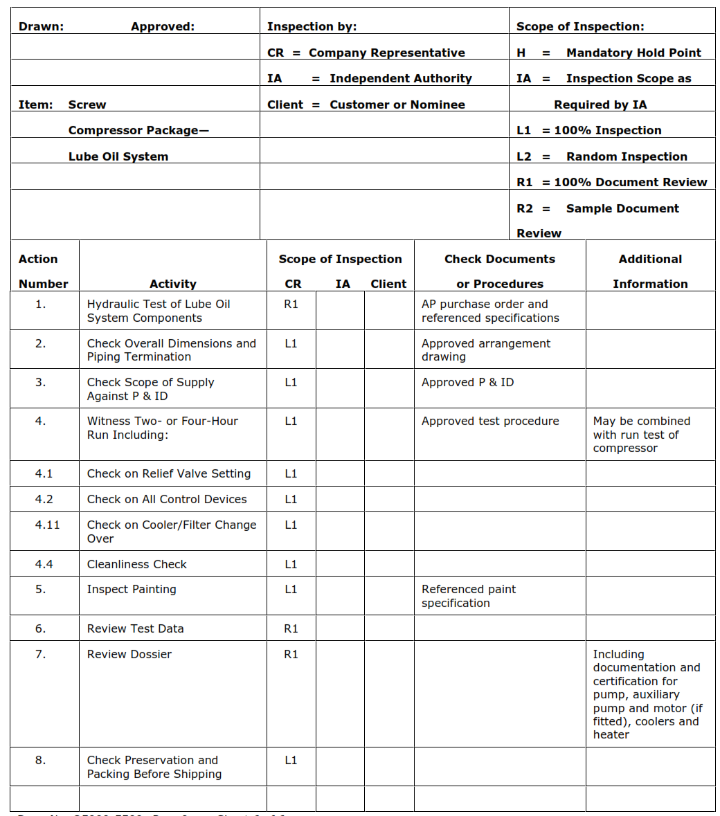
| 23 | Inspection and Testing |
| 24 | Painting and Preparation for Shipping |
| 25 | Tagging, Language, and Units |
| 26 | Drawings and Information |
| 27 | Proposals |
| 28 | Change Log |
| 29 | Compressor Skid Instrumentation |
| 30 | Capital Spare Parts Provisioning |
| 31 | Quality Control Plan, Principal Stages of Inspection |
2. SCOPE
2.1 This specification applies to screw compressor systems that require the compressor and auxiliaries to operate continuously for up to three years, 24 hours per day, at rated load, without shutdown for maintenance of the compressor or the auxiliary equipment.
3. Related Articles
4WEL-20 Medium Voltage Motors
4WEL-P08 IEC Low Voltage Motors
4WEL-P25 IEC Electrical Equipment Installed on Mechanical Equipment Packages within a Nonhazardous Area
4WEQ-1010 Supplier-Designed, Shop-Fabricated Pressure Vessels
4WEQ-1430 Shell and Tube Process Heat Exchangers and Compressor Coolers
4WGN-10001 Shipment and Packing Specification for Equipment and Materials being Exported Directly by Vendors
4WPI-EW80010 Safety Relief Valves
4WPI-EW80016 3-Way Diverter Valves Used as Relief Devices on Cooling Water Systems
4WPI-SW70001 Standard Clean (Class SC) Inspection and Acceptance Requirements
4WPS-INST01 Pressure, Differential Pressure, Temperature Transmitters
4WPS-PRES01 Pressure Gauge, Mechanical (Bourdon Tube Type)
4WPS-TEMP06 Temperature Sensors and Thermowells for General Service
4WPS-TEMP08 Bimetallic Temperature Indicators (Dial Type)
4WPS-VALV10 Instrument Manifold Valves
Engineering Documents (European-Engineered Facilities Only)
C11 Pressure Vessels and Heat Exchangers for Hydrogen Service
4WCE-670200 Fabrication and Erection of Process Piping
Engineering Documents (U.S.-Engineered Facilities Only)
4AEL-620305 Electrical Work on Equipment Skids (Section 4)
4PS00003A Approved Supplier List – HyCO Instrumentation and Control Valves
4PS51002A Instrumentation Tubing Hookup Details
4PS51005A Field Instrument Support Details
4PS52002A Stainless Steel Tubing, Fittings, and Valves for Instrument Service 170 bar g (2500 psig) Maximum
4PS52005A Electrically Traced Tubing for Instrument Service
4WEL-52312 NEMA Standard Reliability Low Voltage Induction Motors
4AEL620301 Hazardous Area Requirements for Class I Areas
4AEL-620302 Standard Wire and Cable Types
4APS-630290S Instrumentation Work on Equipment Skids (Sections 5-8, 12, 17)
4API-630292 Instrument Air Supply Piping Specification
STD-G307A Electrical Standard Grounding High Voltage Motor and Compressor
STD-P306A Electrical Standard Conduit Connection Solenoid Valve
STD-P308A Electrical Standard Conduit Connection To Pigtailed Switch
STD-P309A Electrical Standard Conduit Connection to Field Devices-Class 1 Hazardous Areas
STD-P314A Electrical Standard Temperature Element Connections
3.2 Anti-Friction Bearing Manufacturer’s Association (AFBMA)
STANDARD-9 Load Ratings and Fatigue Life for Ball Bearings
3.3 American Gear Manufacturer’s Association (AGMA)
6011-I03 Specification for High Speed Helical Gear Units
3.4 American Petroleum Institute (API)
API STD 618 Reciprocating Compressors for Petroleum, Chemical, and Gas Industry Services
API STD 619 Rotary-Type Positive-Displacement Compressors for Petroleum, Petrochemical, and Natural Gas Industries
3.5 American Society of Mechanical Engineers (ASME)
BPVC Sect. VIII, Div 1 Pressure Vessels
B16.5 Pipe Flanges and Flanged Fittings NPS 1/2 Through NPS 24
B31.3 Process Piping
PTC 9 Displacement Compressors, Vacuum Pumps and Blowers
3.6 British Standards Institution (BSI)
PD 5304 Code of Practice for Safety of Machinery
3.7 European Council/Commission Legislative Documents
Machinery Directive (89/392/EEC, 93/44/EEC, 93/68/EEC)
EMC Directives (92/31/EC, 93/68/EEC)
Low Voltage Directive (73/23/EEC, 93/68/EEC)
Pressure Equipment Directive (97/23/EC)
3.8 International Electrotechnical Commission (IEC)
IEC/TR 60079 Electrical apparatus for explosive gas atmospheres
DS EN 60529+A1/IP56/IP65 Degrees of protection provided by enclosures (IP Code)
3.9 International Standards Organization (ISO)
1940 Balance Quality of Rotating Rigid Bodies
3.10 National Fire Protection Association (NFPA)
NFPA 70 National Electrical Code™ (NEC)
3.11 Tubular Exchanger Manufacturers Association (TEMA)
TEMA Standards
3.12 U.S. Department of Labor – Occupational Safety and Health Administration (OSHA)
Code of Federal Regulations (CFR), Title 29, Labor
29 CFR, Part 1910 Occupational Safety and Health Standards
3.13 Verein Deutscher Ingenieure (VDI)
VDI 2045 Acceptance and performance tests on turbo compressors and displacement compressors; test procedure and comparison with guaranteed values
3.14 The documents listed in Section 3, by reference, form a part of this specification and refer to the latest edition and addenda in effect at date of manufacture of any item covered by this specification. Any conflicts among the referenced documents that are not resolved by this specification shall be brought to the immediate attention of Air Products.
4. GENERAL
4.1 The following requirements are considered by Air Products to be sound engineering practices that provide reliability and robustness. However, if these requirements cannot be met, Air Products is willing to discuss alternatives. In addition, the supplier is encouraged to propose alternatives based on their experience that adds technical and/or commercial value to their offering. Any decision on the acceptability of alternatives shall be approved in writing by Air Products.
- Paragraphs annotated with a bullet “•” to the left of the paragraph number indicate a project specific requirement and may be specified in the Project Technical Specification that is to accompany this Global Engineering Specification.
4.2 To the extent possible, the compressor selection shall be the supplier’s standard product conforming to the supplier’s normal quality, scope, and design. Requirements contained herein are minimums necessary to achieve the high reliability and availability expected of process gas compression facilities. When the supplier’s standard product differs from these requirements, the exceptions shall be identified including the reasons for the differences. The supplier shall also state their experience with the machinery containing these features in the proposal for Air Products’ evaluation.
4.3 The compressor unit will be located at the site elevation, subject to the ambient conditions, and provided with cooling water at the specified temperature, as listed on the site conditions and utilities data sheet in the job-specific Project Technical Specification.
4.4 The general scope of supply shall consist of a motor-driven screw compressor mounted on a common skid that includes compressor, drive motor, suction scrubber (when specified in the Project Technical Specification), gas coolers, recycle valve, lube oil system with oil and water separators (if required), and all associated piping. A direct mounted motor/compressor combination on a pressure vessel is not allowed unless specifically approved by Air Products. In addition, pressure relief valves (PRV) and suction and discharge check valves shall be provided and installed on the compressor skid.
4.5 If size permits, the preferred arrangement is for the compressor and all the ancillary items to be packaged on a single baseplate, including the drive motor if this is practicable. If the baseplate consists of multiple units, they shall be of a bolted design and doweled together at a trial assembly in the supplier’s works before shipment. The purpose of the common baseplate is to facilitate a full trial assembly and minimize the site work. A “portable” compressor unit is not the intention.
4.6 The supplier’s scope of supply shall consist of the design, fabrication, drawings and data, assembly, painting, testing, and all sub-supplier coordination for the compressor unit.
4.7 The supplier shall provide, as a minimum, all of the equipment detailed in the data sheets. Additionally, the supplier shall provide any other items considered essential for the safe, stable, and reliable operation of the compressor unit.
4.8 When a third party approval or certification is required, the supplier shall be responsible for arranging such certification directly with the appropriate certifying authority and for obtaining such approval or certifications.
4.9 For installations in countries within the European Union (EU), all equipment covered by this specification shall be according to all relevant EU directives and standards. To signify compliance, a “CE” mark shall be affixed to the machine.
4.9.1 The Declaration of Conformity or Incorporation as required by each of the relevant EU directives shall be bilingual—in English and in the national language of the country in which the equipment will be used.
4.9.2 Copies of the equipment manuals and operating instructions and any other information required by the EU directives shall be provided in English and in the national language as specified in the Project Technical Specification. Any written safety instructions, markings, and/or labeling attached to the machine shall be supplied in the national language.
4.9.3 When the supplier is located outside of the European Union or is only required to provide a Declaration of Incorporation under the Machinery Directive, access to the Technical File (as defined by the Machinery Directive) shall be given to Air Products on demand at any time up to the end of the warranty period. The purpose of this is to facilitate review of the supplier’s Safety Risk Assessment.
4.9.4 Regardless of the suppliers’ location, all items of equipment falling within the scope of the Pressure Equipment Directive shall be CE marked and be supplied with a Declaration of Conformity with the PED. If the supplier is located outside of the EU and does not have an authorized agent within the EU, the supplier shall provide Air Products with a copy of all Technical Files relating to CE marked pressure equipment. If the supplier is located within the EU or has an authorized agent located within the EU, then the supplier or authorized agent shall hold the Technical File for a minimum period of 10 years. Pressure equipment that is outside of the scope of the PED or that is classified as being Sound Engineering Practice may not be CE marked; in such cases the supplier shall issue a certificate declaring exemption from the PED.
5. GUARANTEES
5.1 The compressor performance shall be guaranteed to satisfy the operating requirements and power guarantees stated within the Project Technical Specification. The supplier shall state the tolerance applicable to capacity in the proposal. Power requirements at the specified conditions shall include all running-gear losses, seal losses, and all consumption from frame-driven auxiliaries. The supplier shall state the tolerance applicable to the guaranteed power in the proposal.
5.2 When the driver is supplied with the unit the guaranteed power shall be quoted both as shaft horsepower and power required by the driver (that is, kW input), with tolerance and losses as detailed in paragraph 5.1.
5.3 The compressor system shall operate satisfactorily with 0% delivered flow using a combination of internal slide valve (if used) and/or external recycle flow.
6. COMPRESSOR PACKAGE DESIGN
6.1 The compressor, electric motor driver, gas coolers, and auxiliaries shall be mounted on a common skid as stated in paragraph 4.5.
6.2 The supplier shall state in their proposal if the equipment furnished by the supplier exceeds a sound pressure level (SPL) of 90 dBA when measured at any point 1 m (3 ft) from the compressor baseplate at an elevation 1.5 m (5 ft) above floor level (grade).
6.3 The compressors and drive systems shall be mechanically suitable to run safely and reliably at the stage relief valve set pressure at rated compressor speed. When specified in the Project Technical Specification the compressor and all of the components at the suction of the compressor (for example, suction vessels, piping, valves, and fittings) shall be rated for the same MAWP as the discharge of the compressor. Drive system power rating needs to include operation at the stage relief pressures.
6.4 The compressor skid shall be provided with a minimum of 20 mm (0.75 in) anchor bolts located at a maximum of 1.22 m (4 ft) on center, with bolt hole clearance being 20% of the nominal bolt diameters. The anchor bolt locations shall start a maximum of 0.5 m (1.5 ft) from each edge of the skid. Compressor skids shall be provided with a minimum 20 mm (0.75 in) vertical jackscrews at each anchor bolt location to aid in the alignment and tightening down of the skid onto its grouting. Horizontal and vertical jackscrews shall be provided on all major components that require positioning for train alignment. All shims shall be stainless steel. The maximum thickness of any shim pack shall be 0.8 mm (0.030 in). Any shimming required that is greater than 0.8 mm (0.030 in) thick shall be solid metal blocks. In addition, three machined pads shall be provided for alignment and leveling purposes.
6.5 All auxiliary equipment including the lube oil system shall normally be packaged and mounted on the compressor skid.
6.6 The compressor skid shall be sufficiently rigid to permit lifting without distortion or other damage to the skid or any components mounted on the skid when using a four-point lift. Lifting lugs shall be provided with lifting instructions.
6.7 Compressor skids shall be provided with two earthing (that is, grounding) lugs, one at each opposite end of the skid. In addition each major component on the skid [compressor, gear (if used), motor, and motor terminal box] shall be grounded with a ground cable network. The component ground cable network shall be terminated separately at site installation from the skid grounding lugs.
6.8 All structural members shall be “full depth” to facilitate cementatious, nonshrink grouting of the skid base. Bottom corners of skids shall have 50 mm (2 in) radius corners to prevent stress concentration in the grout. Provision for drainage of all skid members shall be supplied to prevent accumulation within the skid of liquid runoff from wash down of the skid, rain/snow (if outdoors) and any potential lubricant or process leaks.
6.9 Skid components shall not be mounted below the top of skid steel base frame. This includes piping, tubing, fittings, instruments, and vessels and any other components of the compression system. The skid design shall allow filling of the skid members with secondary sand cement grout if approved by Air Products after startup to remedy vibration issues and/or maintenance access.
6.10 Full consideration at the design stage shall be given to the provision of any temporary bracing and other supports that might be required for shipment and/or lifting of the skid.
6.11 The design of a skidded arrangement shall provide adequate access for operation and maintenance. The supplier shall be required to demonstrate that adequate space has been allowed. The requirements for good maintenance access to the compressor and low gas pulsations during operation are of extreme importance when considering the pipe work arrangement. The supplier’s design shall attempt to maintain the compressor and pipe work as low as practical. This is to minimize vibration.
6.12 While it is preferred to operate the compressor at all speeds within the speed range required to meet the range of operating duties specified, nonoperational speed bands will be considered when specified by the compressor supplier.
6.13 All vent and drain connections, including strainer drains, shall be provided with plugged valves.
6.14 When specified in the Project Technical Specification, the compressor shall have a 5 micron process gas inlet filter. Process filter vents and drains shall terminate with a screwed plug on the outboard end of the valve and socket-weld connection on the process side of the valve. Filter housings shall be furnished with quick-opening top heads and weld end nozzles. Lifting davits shall be provided on top heads. Filter elements and their supports shall be able to withstand a 1.7 bar (25 psi) pressure differential in both flow directions without collapsing. Element mounting hardware shall be constructed of stainless steel.
6.15 All enclosures and guards shall meet the requirements of BS 5304 (European Market Designs / Applications) or OSHA 29 CFR, Part 1910, paragraph 219 (for all other applications). Guards shall be an aluminum, nonsparking design with a maximum magnesium content of 0.6%. Expanded metal is not permitted.
6.16 All piping connections on machined casings shall be located in three dimensions to + 3 mm (1/8 in) from a predefined datum on the package. Connections to fabricated piping shall be located in three dimensions to + 25 mm (1 in). Other noncritical termination locations (for example, cables) shall be sufficiently accurate for basic location and orientation to enable racking routes to be established for junction boxes and power cable terminations unless otherwise agreed at time of order placement.
7. COMPRESSOR DESIGN
7.1 The compressor(s) shall be of the dry, water-flooded or oil-flooded rotary screw type as identified in the Project Technical Specification. The dry type units shall be furnished with timing gears. Oil- and water-flooded type units can be furnished without timing gears.
7.2 The lobes shall be machined from solid forged alloy steel blanks. The lobes shall be individually dynamically balanced. The residual unbalance in any correction plane of the assembly shall not be greater than:
Where:
U = Residual unbalance, oz-in
W = Assembled rotor weight, lb
N = Maximum operating speed of rotor, rpm
Note: This criteria corresponds to Balance Quality Grade G2.5 of International Standards Organization Recommendation 1940, Balance Quality of Rotating Rigid Bodies.
7.3 The compressor shaft shall be made of alloy steel, preferably the same material as the lobes.
7.4 Timing gears or speed increasing (or decreasing) gears internal to the compressor casing shall be designed to a recognized code (AGMA or DIN) and be capable of 15 years continuous operation without replacement or repair of major rotating components.
7.5 The complete rotating assembly shall be held together in such a way that all individual parts comprising the assembly will remain securely held in their proper location under all conditions.
7.6 Ball, roller, or sleeve bearings are acceptable. Suitable thrust bearings shall be provided as required to allow continuous compressor operation over the range of suction pressures specified in the Project Technical Specification. Alternately, sleeve type radial bearings and tilt pad thrust bearings must be supplied if required in the Project Technical Specification.
7.7 Ball or roller bearings shall be designed to provide a minimum L-10 life per AFBMA Standard 9 of 100,000 hours with continuous operation at rated operating conditions, but not less than 75,000 hour L-10 life at maximum axial and radial loads and rated speeds.
7.8 When sliding type bearings are used, the journal bearings shall be precision, replaceable shell or sleeve type. All bearings shall be lubricated with a positive pressure lubrication system.
7.9 The compressor casing shall be made of cast or ductile iron. For flammable and/or toxic gas applications, casing material shall be ductile iron or steel.
7.10 The minimum design operating pressure of the casing and head plates (pressure containing components) shall be at least equal to the maximum discharge relief valve pressure setting.
7.11 The casing design pressure shall be consistent with piping system design pressures developed in accordance with the criteria in Section 13.5.
7.12 The thickness of the casing and head plates shall be suitable for the maximum pressure defined above and shall include at least 1/8 inch corrosion allowance. The casings and head plates shall be designed to prevent detrimental distortion caused by the pressure load. The hoop stress value at any point shall not exceed the value given in the ASME Boiler and Pressure Vessels Code, Section VIII, Division 1 for the casing material used. Materials, for casings and forgings and the quality of any welding shall be equal to that required by the code. All welding shall be suitably stress relieved.
7.13 Any casing repairs shall be discussed with and agreed to by Air Products in writing before the repair work begins.
7.14 Lifting eye bolts and tapped jackscrew holes shall be provided on all major components weighing 75 pounds or more.
7.15 An arrow designating the correct direction of rotation of the compressor shaft shall be permanently affixed to the casing. Casting of the arrow on the casing is preferred.
7.16 A corrosion-resistant nameplate shall be attached to each compressor. The nameplate shall show size, serial number, capacity, operating pressures, operating speed, and bearing manufacturer’s identity numbers.
7.17 Unless indicated in Project Technical Specification, the compressor casing shaft seal shall be a single mechanical face type oil cooled seal. This seal shall be designed for maintenance and replacement without disassembly of the compressor housing.
7.18 If the installation site local regulations limit the fugitive emission of the process gas, then in lieu of the mechanical seal in paragraph 7.17, the Project Technical Specification may require a double mechanical seal be supplied and be purged and vented to an Air Products supplied vapor recovery system.
7.19 When specified in the Project Technical Specification a compressor shaft dry gas seal shall be supplied in lieu of the mechanical seal in paragraph 7.17.
7.20 Dry and water-flooded type compressors shall be furnished with shaft seals between the bearings and the process gas side to prevent oil from leaking into the process or water leaking into the bearing chambers.
7.21 When water or oil flooded screw compressors are being supplied, the compressor shall be furnished with a slide valve capacity control system capable of controlling the compressor flow from 100% to a minimum of 20%. The slide valve shall be activated by an electric motor with adjusting gear or a hydraulic cylinder. The adjustment device shall have an external indicator and a limit switch (for permissive start) indicating slide valve position. When hydraulic cylinders are used, the hydraulic fluid shall be taken from the common compressor lubrication system. This requirement does not eliminate the system operating requirement stated in paragraph 5.3.
7.22 Compressor vibration shall not exceed the limits indicated in API STD-619, Table 1, Vibration Limits for Screw Compressors.
7.23 Screw Compressor design shall be such that the internal volume ratio and oil temperatures shall maintain a minimum of a 5°C (10°F) difference between the internal gas temperature and any fluid constituent dewpoint to prevent condensation in the gas from forming.
8. COMPRESSOR DRIVES
8.1 All compressors shall be direct coupled with spacer type disc pack flexible couplings. The coupling spacer shall allow removal of the compressor shaft mechanical seal without compressor or driver removal or re-alignment. Coupling hubs shall be fitted with threaded holes for removal from shaft.
8.2 Speed increasing gears shall be in accordance with a recognized code (AGMA or DIN) and be capable of 15 years continuous operation without replacement or repair of major rotating components. The design shall allow the replacement of a pinion without changing the bullgear. The gears shall be class 12 and shall have a 1.75 minimum service factor.
8.3 External speed increasers (when supplied) shall have a gear mesh rating that meets the requirements of AGMA 6011-I03 and shall be capable of withstanding up to 5 times normal torque expected during start-up and transient operations.
8.4 External speed increaser gear mesh shall meet the minimum values for service factors Csf and Ksf specified in AGMA 6011-I03. Calculations demonstrating compliance shall be made available on demand.
8.5 Speed increasing gear units shall be supplied with a complete individual lubrication system separate from the compressor lubrication system for oil-flooded screw compressor systems. The gear lubrication system shall meet the requirements of Section 15, Lubrication System. The gear case may be used for the gear oil reservoir.
8.6 Speed increasing gear units shall be rated for driver nameplate horsepower plus driver service factor.
9. DRIVE MOTORS
9.1 The supplier shall take prime responsibility for the mechanical integration of the motor and the compressor. This will include, but not be limited to, specification of the coupling details, accommodation of any axial forces on the drive shaft assembly, ensuring adequate inertia is provided in the rotating assembly, torsional analysis of the compressor (when specified in the Project Technical Specification), gear (if used), and motor train, and incorporation of the drive motor into the general arrangement and the skid drawings. The compressor supplier is responsible for ensuring that the entire motor rotor is reviewed during the torsional analysis (including poles and pole attachments).
9.2 Medium voltage motors (larger than NEMA frame sizes in the U.S.) shall be according to 4WEL-20. Medium voltage motors shall be provided with sniffing or sensing ports, and purge ports in the frame to check for and purge flammable gas in hazardous area classifications before motor start if specified in the Project Technical Specification.
9.3 The inertia of the rotating parts of the combined motor-compressor installation shall be sufficient so that the amplitude of the cyclic line current pulsation caused by the compressor is limited to 66% of motor full load current measured peak-to-peak. The system shall also have sufficient inertia to allow the motor to approach steady running efficiency.
9.4 Low voltage main drive motors and/or motors for auxiliary equipment shall be according to 4WEL-P08 for IEC and NEMA frame motors.
9.5 When specified in the Project Technical Specification, the drive motor terminal box shall be supplied in accordance with Air Products motor terminal box designs.
10. CAPACITY CONTROLS
10.1 The compressor capacity shall be controlled as indicated in the Project Technical Specification data sheets. A compressor external recycle control valve shall be provided and piped by the compressor supplier. For screw compressors supplied without an internal flow control valve, the external recycle valve shall be sized for 0% to 100% recycle flow with proper valve flow coefficient (CV) for control. When a screw compressor internal capacity control valve is supplied, the external recycle valve shall be sized for a minimum of 20% greater than the minimum compressor capacity when using the internal capacity control valve.
10.2 A manual bypass valve sized to allow full flow with the recycle valve fully open shall also be provided. The manual bypass valve sizing shall be based on compressor capacity with any stage discharge temperature limited to the maximum allowable operating temperature.
10.3 The recycle gas shall be taken after a gas aftercooler (when supplied). A gas recycle cooler shall be provided if a gas aftercooler is not included in the scope.
10.4 Automatic recycle unloading shall be provided to adequately unload the compressor during starting and stopping. Final discharge unloading and necessary interstage unloading shall be provided to limit compressor starting and pull-in torque to 20% of full load torque. All recycle (bypass) flows shall be from the downstream side of the gas recycle cooler or gas aftercooler.
10.5 The final discharge recycle valve shall be required regardless of starting torque and shall be suitable for continued throttling without damage to the valve.
10.6 The suction, any interstage, and discharge relief valves shall be provided by the supplier in accordance with 4WPI-EW80010 and installed (For Air Products use only: Sized according to Air Products Recommended Practice EP4.6) on the compressor skid.
11. Pressure Vessels
11.1 All pressure vessels shall meet the requirements of 4WEQ-1010 and C11 (if applicable). Only the following sections of 4WEQ-1010 apply
5.2 Codes
6 Materials and Corrosion Allowances
7 Nozzles and Flanges
9 Supports and Lifting
11 Fabrication and Workmanship
16.5 Marking of Heat Treated Pressure Vessels
Appendix A Additional Requirements for Toxic or Flamable Services
Appendix B Additional Requirments for Reciprocating Compressor Service
European-executed projects shall also meet the requirements of the European Pressure Equipment Directive (97/23/EC). Any specific inspection requirements will be detailed in the Project Technical Specification.
11.2 The Project Technical Specification will advise the supplier of any special pressure vessel requirements of the local jurisdiction including any wind and seismic load requirements.
12. GAS COOLERS
12.1 TEMA C gas coolers provided according to 4WEQ-1430 may be used for process gas applications. However for flammable and toxic gas applications, gas coolers shall be provided according to 4WEQ-1430 and designed according to TEMA R, Type BEM. Air Products specification C11 applies for European plant locations for compressors in hydrogen service. European-executed projects shall also meet the requirements of the European Pressure Equipment Directive (97/23/EC).
12.2 Clarification of Section 8.1 of 4WEQ-1430: Tube bundles shall have fixed tube sheets unless removable bundles are specified in the Project Technical Specification. Gas coolers with cooling fluid in tube side shall be mounted with adequate space at one end minimum for rodding out with the cooler in place on the skid.
12.3 When specified in the Project Technical Specification, a gas intercooler and/or aftercooler shall be provided after each stage of compression. Gas temperature after the intercooler will be a maximum of 40°C (104°F).
12.4 Unless otherwise specified in the Project Technical Specification, the fouling factors and minimum velocities shall be 0.000176 m2-C/W (0.001 hr-ft2-F/BTU) for gas, lube oil, and cooling water.
12.5 Coolers shall be equipped with plugged connections between each baffle for agitation connections per Section 8.12 of 4WEQ-1430.
12.6 All coolers shall be mounted and piped by the supplier on the compressor skid such as to be self draining on the gas side and drain in the direction of the normal gas flow. Any pockets or traps where fluid can collect shall be provided with a drain valve. If the wet gas condensates are present during normal operation, the cooled recycle flow shall be returned to a suction separator vessel. If wet gas condensates are present only during startup operation and if a suction separator is not provided, a low point drain valve downstream of the cooled recycle stream shall be supplied to remove condensates before the compressor suction during wet gas startup operation.
13. PIPING AND VALVES
13.1 All piping and applicable fittings shall meet the requirements of ASME B31.3 unless otherwise specified in the Project Technical Specification. Process piping shall have raised face flanges according to ASME B16.5. Cast iron or nodular iron casings may have flat face flanges drilled for compatibility to raised face flanges. Weld neck flanges shall be used on all connections subject to cyclical stress.
13.2 The gaskets shall be Flexitallic (U.S. manufacture) or Lamon equivalent. The Flexitallic is a Style CGI 316L or 304, stainless steel, spiral wound gasket with stainless steel inner gauge ring, carbon steel outer ring and Flexicarb filler. Substitutes other than Flexitallic or Lamon are not permitted. The finish of the gasket contact surface for flanges where Flexitallic or Lamon gaskets are installed shall be an RMS finish of 3.2 to 6.4 micrometers (125-250 microinches). Either a serrated-concentric finish or a serrated-spiral finish having a pitch of 0.6 to 1.0 millimeter (24-40 grooves per inch) shall be used.
13.3 Piping and appurtenances shall be according to 4WCE-670200 for European-engineered products.
13.4 To minimize the potential for leaks, use of flanged joints shall be minimized. Screwed connections are not permitted, with the exception of instrument and temperature connections up to DN20 (NPS 3/4) NPT.
13.5 The supplier shall be responsible for determining the design pressure for all piping systems within the compressor package.
13.5.1 The relief valve set pressure which will normally determine the piping system design pressure shall be derived from the following guidelines:
-
- Suction relief valve: Design pressure of the customer-provided suction piping system, or the equilibrium pressure that could be achieved when the compressor discharge inventory is equalized into the volume of the suction piping system.
- Interstage relief valves: The interstage pressure achieved when the compressor is operating at the maximum operating suction pressure stated in the duty specification, including the pressure caused by allowable pulsations plus a 15% margin or 1 bar, whichever is greater.
- Final discharge: Design pressure of the customer-provided discharge piping system, and/or the pressure derived using the same method as for interstage relief valves, but with the margin reduced to 12%.
13.5.2 When relief valves are supplied, accumulation shall be limited to 10%. The capacity of all relieving devices shall consider all possible upset and off-design conditions, which can occur during a fire case, start-up, shutdown, and normal operation. The supplier is expected to work with Air Products to come to a safe design using the following as guidelines:
Suction relief valve: The greater mass flow established from the following situations:
– Compressor flow rate at the maximum operating suction pressure stated in the equipment specification.
– Transient flow rate as a result of the recycle valve failing open during compressor operation.
– Flow rate as a result of a failure of the nonreturn valve and the recycle valve fully open when compressor is shut down. Unless otherwise specified in the Project Technical Specification, the flow computed for the reverse leakage flow of the non-return valve shall assume 5% of the non-return valve Cv applied across the pressure difference of the non-return valve based on pressures upstream (low pressure side) and downstream (high pressure side) of the non-return valve during the relieving case.
– Flow rate as a result of running-in gas supply valve failing open when connected to a high pressure source.
Interstage and final relief valve:
– Mass flow rate for the compressor when operating at the relief valve set pressure of the suction system with an allowance made for piping pressure drop between the relief valve and the compressor suction.
Relieving devices on ancillary systems:
The mass flow rate achieved as a result of the worst case for that system in the event of malfunction of valves or other devices within the system allowing venting of high pressure gas into a lower pressure system.
Pilot-type relief valves with backflow preventer and gas spike snubber shall be used whenever the built-up back pressure in the venting system can exceed 10% of the relief valve set pressure. Each relief valve shall meet all requirements of the specified statutory authorities and be provided with an individual test certificate.
13.5.3 All relief valves shall be provided with flanged connections.
13.5.4 The design pressures for the customer-supplied piping system at suction, discharge, and any interstage terminations are specified in the Project Technical Specification compressor data sheets.
13.5.5 The piping system test pressures shall be determined from the piping design code. Hydro testing of completed compressor, vessels, and piping system is not allowed without written approval by Air Products.
13.5.6 Redundant safety valves each sized for 100% required relieving flow shall be supplied when a system source pressure upstream of an automatic pressure regulator which opens on regulator failure is 3 times the safety valve set pressure.
13.5.7 When specified in the Project Technical Specification redundant safety valves each sized for 100% relieving flow shall be supplied for applications requiring extended continuous operation without shutdown. Each safety valve shall be capable of isolation and removal for testing while the other valve remains in service.
13.6 Flooded compressor packages shall include a suction check valve in the suction piping. All compressor packages shall include discharge check valve in the discharge line. All compressor connections shall terminate at the edge of the skid.
13.7 Liquid systems shall be provided with sufficient vent and drain connections to allow complete venting or draining. All low points in gas lines shall be provided with drain connections.
13.8 Each compressor process inlet shall be provided with a protective strainer. These strainers shall be a fully conical or “witch’s hat” type. A truncated cone design is not permitted. The strainers shall be mounted horizontally in a flanged spool piece. Strainers shall be sized for 150% of the pipe cross‑sectional area. The strainer shall be able to withstand 10.3 bar (150 psi) differential pressure without collapsing. The strainer shall be constructed of a 100-mesh screen and a center-reinforcing 20-mesh screen backed by a perforated conical cone. In corrosive or non-lubricated service, the strainers shall be of all stainless steel construction. Strainer flanges shall have a phonographic 125–250 AARH finish.
13.9 Control valve calculations shall show that the valves are correctly sized to account for all possible operating conditions and are stable over the complete operating range.
13.10 Tube fittings shall be Swagelok or Parker A-LOKÒ.
13.11 When specified in the Project Technical Specification, equipment located adjacent to operator walkways around the edge of the skid or on-skid access walkways that operate with external surface temperatures at or above 65°C (150°F) shall be equipped with insulation or heat shields for personnel protection in accordance with applicable specifications in Section 3.1. The insulation or heat shield for personnel protection is to be installed to a minimum height of 1.8 m (6 ft) above the respective walkway.
13.12 When specified in the Project Technical Specification, a complete local cooling water distribution system shall be supplied to provide gas intercooling and aftercooling (if specified) and oil cooling. The system shall be complete with all heat exchangers, interconnecting piping, control valves, sight glasses, temperature gauges, low point drains and drain valves, high point vents and vent valves. Only one water inlet to the system and one outlet connection from the system shall be provided.
13.13 When specified in the Project Technical Specification an oil condensate return line with a sight glass, globe valve, and strainer shall be supplied in the gas cooler outlet line to return condensed oil to the compressor suction in a continuous flow.
13.14 The cooling water system components shall be designed for a minimum of 10.3 bar g (150 psig) at a MAWT of 65.6°C (150°F).
13.15 When heat exchanger cooling water piping is specified to be provided by the vendor, a 3-way diverter valve shall be used in lieu of a relief device to provide over-pressure protection for the thermal and slow tube leak cases where the heat exchanger is blocked in. The 3-way diverter valve shall be provided, sized, and installed in accordance with 4WPI-EW80016.
14. PULSATION DAMPING
14.1 Adequate pulsation damping shall be provided to limit the pressure pulsations or forces within the compressor system. The system shall include all piping, including laterals (for example, relief valve lines or bypass lines) within the skid limits.
14.2 The pulsation suppression design shall be according to API STD 618 Design Approach 1, except that the allowable upper limits of peak-to-peak pressure pulsations, expressed as a percentage of the mean absolute line pressure, at the inlet and discharge shall be as follows:
Line Pressure, bar a (psia) Peak-to-Peak Pulsation, %
| 2.07 (30) and below | 5.0 |
| 3.45 (50) | 4.2 |
| 6.90 (100) | 3.3 |
| 17.20 (250) | 2.4 |
| 34.50 (500) and above | 1.9 |
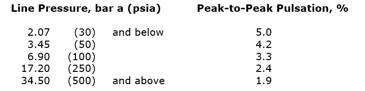
Note: When interpolation of the above tabulation is required, it shall be calculated according to the equation:
% Pulsation = 16.9(P)-0.353 for P in psia
% Pulsation = 6.57(P)-0.353 for P in bar a
where P is the mean absolute line pressure. The vibration level will be verified during commissioning. When specified in the project Technical Specification, a mechanical vibration analysis shall be performed during the design phase.
14.3 Pulsation generated unbalanced forces in all piping shall be within the following limits:
- For f < 30 Hz:
Fmax < 17.5 * D up to 4,500 in Newtons
(Fmax < 100 * D up to 1,000) in lbf
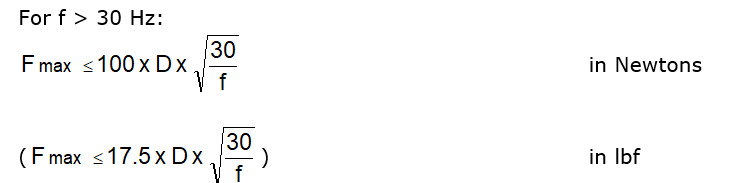
where: Fmax = maximum allowable unbalanced force in Newtons (lbf)
D = nominal pipe diameter in mm (in)
f = forcing frequency, Hz
14.4 The pulsation limits are subject to field verification. The supplier is responsible for making corrections to meet the limits. Piping and piping component vibration shall not exceed:
25 mm/sec (1 in/sec) peak velocity
14.5 The mechanical natural frequencies of all vessels and piping within the supplier’s scope of supply shall be less than 30 Hz or 2.4 times the compressor running speed, whichever is greater.
14.6 The compressor and ancillaries shall be arranged so that provision is made for the addition of bracing in locations where mechanical vibration might need to be reduced. These locations shall be identified by the supplier and will be discussed at the supplier coordination meeting.
14.7 Pulsation/Separator vessels shall be designed to meet the specified pulsation levels and may incorporate internal components. All nozzle connections shall incorporate reinforcing pads on the vessel. Internal inspection of the vessel shall be possible from the main process nozzle connections if separate vessel inspection openings are not provided.
14.8 Vertical pulsation/separator vessels that require fixing to the foundation shall use skirts on the vessels to provide a stiff support.
14.9 Pulsation/Separator vessel low point drain connections shall be a DN40 (NPS 1 1/2) minimum piped to a common drain connection at the baseplate edge. Drain connections shall be supplied with gate-type isolation valves for each pulsation bottle which shall be located close to the respective vessel. Suction pulsation vessels in dry gas applications do not require a drain connection, but instead shall be designed as free-draining to the compressor suction.
14.10 The pulsation levels shall meet the criteria specified in paragraphs 14.2 to 14.5 under all of the following conditions:
- Normal operation.
- Operation of compressors in parallel, if relevant.
- Operation of compressor on recycle.
- Operation at variable speed, if relevant.
- Operation over the full range of pressures and flows specified.
14.11 The pulsation levels shall be acceptable when considering the correct molecular weight or range of molecular weights of the gas being compressed. For flammable or toxic gas applications, when the safe operation of the gas compressor package must be proven using nitrogen during initial commissioning, consideration shall be given to including this case.
14.12 When Air Products’ pipework design details are required to maintain acceptable pulsation levels, it is the supplier’s responsibility to request the details and ensure that the correct boundaries are set. It shall be Air Products’ responsibility to ensure that the details are provided within the agreed time schedule and that the supplier is promptly notified of any subsequent changes made to the pipework.
14.13 The package shall be entirely self-contained on its skid, except for customer connections. No supports to adjoining equipment or buildings shall be permitted. Forces in excess of the amount specified in paragraph 14.3, which are caused by pulsations, shall be corrected by damping the pulsations. Mechanical vibrations which are unrelated to pulsations shall be suitably contained by bracing within the compressor package. Bracing shall be neat and orderly and shall not interfere with normal maintenance of the compressor.
14.14 Field modifications needed to reduce pulsations or reduce vibrations shall be entirely the responsibility of the supplier.
15. LUBRICATION SYSTEM
15.1 The compressor shall have a forced feed lubricating oil system for bearings, timing gears, and shaft casing seal shell.
15.2 All external oil-containing pressure components including auxiliary oil pumps in systems with design pressures up to 24.1 bar g (350 psig) may have cast iron or nodular iron casings. Steel shall be used for these components above 24.1 bar g (350 psig) system design pressure.
15.3 The main oil pump shall be direct shaft driven or electric motor driven. The supplier shall demonstrate adequate hardness of any splined-type main oil pump coupling to preclude premature wear. Main oil pumps using a gear drive from the primary screw rotor shaft are not acceptable.
15.4 An auxiliary oil pump shall be supplied if specified in the Project Technical Specification. The auxiliary oil pump shall be electric motor driven and shall be a full duty pump. On falling oil pressure, the auxiliary oil pump will start on the low oil pressure alarm signal. When auxiliary oil pumps are specified, maintenance isolation valves shall be supplied in the piping for the main and auxiliary pumps to allow safe isolation for maintenance of the out-of-service pump while the other is in service.
15.5 Main and auxiliary oil pumps shall be manufactured by IMO, Leistritz, or Air Products approved equal. The main and auxiliary oil pumps shall have a mechanical seal. Control functions will be provided by the Air Products Distributed Control System (DCS). A local stop button for the main (if electric motor drive) and the auxiliary oil pump shall be provided if required in the Project Technical Specification.
15.6 The oil pump electric motor driver(s) shall be in accordance with 4WEL-P08 for IEC applications or 4WEL-52312 for NEMA applications and shall be suitable for the specified utility power characteristics given in the Project Technical Specification. The motor starter(s) will be provided by others. The oil pump motor(s) shall be sized to not overload during startup of the pump at the minimum lube oil temperature present in exposed piping feeding the pump after extended shutdowns.
15.7 A FulfloÒ (or Air Products approved equal) pressure relief valve shall be supplied sized for the full range of flows with both the main and auxiliary pumps running. To control oil pressure, a pressure control valve (PCV) can be used and shall be sized so that proper and stable control can be obtained without lifting the relief valve over a full range of flows, both with and without the auxiliary oil pump running. Alternately FulfloÒ (or Air Products approved equal) pressure relief valve may be specified to control oil pressure if the relief valve is in addition to the unit providing overpressure protection. A single relief valve to control oil pressure and provide overpressure protection shall not be used.
15.8 A single oil cooler shall be supplied. Tube bundles shall have fixed tube sheets unless removable bundles are specified in the Project Technical Specification. Tube bundles shall be in accordance with TEMA-C above 0.5 square meters (5 square feet) surface area. All oil coolers shall have a minimum 18 BWG tube wall [1.25 mm (0.05 in)]. Tubes shall be a minimum 15 mm (5/8 in) outside diameter and 90/10 Cu/Ni material. The layout of the oil system shall allow adequate space for rodding through the tubes from either end of the cooler. The oil cooler shall be sized for the compressor full load operation and for the complete range of turndown of the compressor. The oil cooler shell MAWP shall be a minimum of 6.9 bar g (100 psig) greater than the MAWP of the primary lubricant removal vessel for flooded screw compressor designs.
15.9 An AMOTÒ (or Air Products approved equal) temperature control valve shall be supplied. Manual override on the AMOTÒ (or equal) temperature control valve is not required.
15.10 A single oil filter sized for 150% of compressor normal oil flow (that is, 150% of total flow through the main oil pump) with a maximum pressure drop of 0.34 bar (5 psi), at design oil operating temperature is required. The pressure drop through the clean filter shall not exceed 0.14 bar (2 psi) at an operating temperature 11°C (20°F) above normal operating oil temperature and normal flow (that is, total flow through the main oil pump). As an alternative, duplex oil filters with integral transfer valve and each filter sized for 100% of compressor normal oil flow (that is, 100% of total flow through the main oil pump), with a maximum pressure drop of 0.68 bar (10 psi), at design oil operating temperature may be provided. The pressure drop through the clean filter elements in the 100% filter size case shall not exceed 0.34 bar (5 psi) at an operating temperature 11°C (20°F) above normal operating temperature with normal flow (that is, total flow through the main oil pump). Oil-flooded compressor duplex filters can be supplied with individual block valves in lieu of a single transfer valve. In all cases the oil filter(s) shall not contain any internal or external bypasses. The filter element collapse pressure shall be above the relief valve setting. Each filter casing shall contain a vent and drain valve.
15.11 When transfer valves are supplied on duplex oil filters (or oil coolers), they shall provide full oil flow at any valve position. The transfer valves shall provide sufficiently tight shut-off to allow for safe opening of the out-of-service filter (or oil cooler). Duplex oil cooler transfer valves shall be independent from those serving the filter set.
15.12 An electric oil reservoir heater is required when ambient temperatures as indicated in the Project Technical Specification data sheets can drop below 5°C (40°F). It shall be sized to heat the oil from minimum ambient temperature to the minimum start temperature for the main or auxiliary oil pump within eight hours. The heater shall incorporate a thermostat. The heater shall be provided with a low oil level shut-off switch only where required by local code. The maximum watt density shall be 2.3 W/cm2 (15 W/in2). Oil heaters shall have automatic over temperature cut-outs to protect against overheating resulting from low oil level.
15.13 When an oil reservoir heater is provided, the exterior of the oil reservoir and all oil piping to the compressor shall be heat traced and insulated in accordance with applicable specifications in Section 3.1.
15.14 The oil reservoir shall be provided with a lube oil level indicator. The indicator shall be accurate when operating with a purged reservoir at design pressure.
15.15 Oil-flooded compressors shall take lubricating oil from the process coolant oil and shall be combined with this system.
15.16 Neither threaded connections or rubber hoses shall not be used in the lubrication system. Oil piping downstream of the oil filter(s) shall be stainless steel with weld neck flanges. Fittings shall be butt weld.
15.17 Each oil pump shall have a pump suction mesh strainer (40 mesh minimum).
15.18 Relubrication intervals for auxiliary equipment (for example, couplings, oil pumps, capacity control valve assemblies, and motor bearings) shall not be less than three years unless the task can be accomplished while the compressor is operating.
16. INSTRUMENTATION AND CONTROL
16.1 Normally, the plant will be controlled and supervised from a central control room using a Distributed Control System (DCS) provided by Air Products. The DCS will contain all programmable logic for all modes of sequencing the package. Local controls shall be minimized and generally restricted to those essential for bringing the equipment from the shutdown and isolated condition to the ready-to-start or ready-to-operate condition.
Note: Starting, stopping, and modulation of the compressor when running will be controlled remotely by the DCS. Critical Product Protection shutdown settings and safety instrumented functions shall not be controlled by the DCS but accomplished with the compressor safety instrumented system. The Project Technical Specification shall specify any such requirements.
16.2 All instrument work shall be according to 4APS-630290S, 4API-630292, 4PS00003A, 4PS51002A, 4PS51005A, 4PS52005A, STD-P314A for U.S.-executed projects, and 4WPS-PRES01 and Air Products-approved IEC requirements for European-executed projects.
16.3 A block and bleed valve manifold is required at all pressure gauges and pressure transmitters. All pressure indicator root valves shall be welded in. All pressure and differential pressure devices shall be supplied with a valve manifold assembly per 4WPS-VALV10.
16.4 The recycle control valve shall be manufactured by Fisher or Air Products approved equal with stainless steel tubing. The recycle control valve shall be suitable for continuous operation and shall fail closed on loss of instrument air. Copper tubing is not allowed. Welded valve connections shall be used.
16.5 Instrument tubing shall be run according to 4PS51002A. Heat tracing and insulation shall be supplied in accordance with 4PS52005A. Conduit runs shall be designed to avoid tripping hazards and provide adequate headroom (that is, no head-knockers).
16.6 An instrument air supply line of DN15 (NPS 1/2) stainless steel tubing shall be run from the recycle valve to the edge of the skid, with a block valve and DN15 (NPS 1/2) x PN20 (Class 150) pipe flange. When more than one device requires instrument air, an instrument air supply header shall be supplied in accordance with 4API-630292.
17 ELECTRICAL DEVICES
- 17.1 Electrical system shall be according to 4WEL-P25 or 4AEL-620301, 4AEL-620302, STD-G307A, STD-P306A, STD-P308A and STD-P309A, as applicable. Unless otherwise indicated in the Project Technical Specification, all electrical devices, including drive and auxiliary electric motors and instrumentation, shall be according to the requirements in IEC/TR 60079, Class 1, Zone 1, EEx d, IIC, T3 for equipment installed within Europe, and an electrical area classification of Class 1, Groups B, C, and D, Division 2 of NFPA 70, Article 500 for equipment installed in the U.S. and outside of Europe. Safety devices shall be provided and installed by the supplier. The supplier shall provide wiring diagrams for all provided electrical devices. All electrical components and installations shall be suitable for outdoor installation.
17.2 Compressor casing-mounted vibration sensors shall be provided as follows (See Table 1):
17.2.1 For standard reliability installations a minimum of one vibration switch shall be provided, and shall be mounted directly on the compressor casing. The use of a cantilevered bracket bolted to the casing to mount the switch is not allowed.
17.2.2 The supplier shall submit for Air Products written approval, the quantity and location of switches to be provided. For standard reliability installations, vibration switches shall be a Robertshaw Model 365A G0. This specifies two single pole, double throw sealed switches with gold plated contacts for low voltage current applications (DPDT) and no reset coil. For projects located in Europe, this switch shall be provided with the CE certification. A Robertshaw Model 365-A8 is not acceptable because of reliability problems. The switch shall be wired close‑to‑run, and open-to-trip.
Note: All vibration switches shall be rated for control power voltage as listed in the data sheet. Switches shall be calibrated and set at the installation site by the supplier’s representative or an Air Products representative.
17.2.3 When specified in the Project Technical Specification, for high reliability installations, Metrix vibration transmitter(s) Model 5484C-121 with 4-20 mA output signal or an equal approved in writing by Air Products shall be provided on the casing exterior for continuous display of casing vibration in the plant DCS. Casings less than or equal to 0.75 m (2.5 ft) length between the axial centerlines of radial bearing spans require a minimum of two velocity transmitters measuring radial casing vibration in the radial plane of the bearings. Casings with bearing spans longer than 0.75 m (2.5 ft) require a minimum of four casing velocity transmitters, two transmitters at each bearing set at opposite ends of the casing measuring vibration in the radial plane of each bearing set.
17.2.4 When specified in the Project Technical Specification, provision for the future installation of Metrix Series 10000 proximity-type radial vibration probes (Catalog No. 10003 with M8X1 thread) or equal approved in writing by Air Products shall be provided. Provision shall be made for two probes per bearing in the radial plane in the “x” and “y” position 45 degrees off the vertical centerline of the bearings. Holes shall be plugged. Flooded screw compressor designs require the approval of Air Products in writing of the probe body and/or probe electrical cable sealing method.
17.2.5 For standard reliability when specified in the Project Technical Specification that long-term operation is required without internal bearing inspection, a minimum of one axial position monitored point per thrust bearing is required. Each proximity probe shall be manufactured by Metrix (or approved equal) and interface with a Metrix Model 5488, 4-20mA transmitter also supplied. It is preferred that each probe be adjustable externally to the compressor casing. Flooded screw compressor designs require the approval of Air Products in writing of the probe cable and/or probe body sealing method.
17.2.6 For high reliability installations three axial position monitored points (or two if three not available) per thrust bearing are required. Probes, transmitters, and wiring shall be supplied per paragraph 17.2.5.
17.3 Pressurized lube oil systems shall be provided with a differential pressure transmitter. The transmitter shall provide signals for a low differential pressure alarm and low differential pressure shutdown. All pressure, differential pressure, and temperature transmitters shall be supplied in accordance with 4WPS-INST01.
17.4 Temperature elements (thermocouples) or temperature indicators (gauges) shall be provided by the supplier. Temperature elements shall be provided on all compressor process piping. All temperature indicators or elements shall be locally mounted in the piping or vessels with DN20 (NPS 3/4) socket-weld connections with separable thermowells allowing for element removal while the compressor is in operation. Any temperature element that initiates a compressor shutdown shall include a temperature transmitter. RTD temperature elements when supplied shall be in accordance with 4WPS-TEMP06. All temperature gauges shall be supplied in accordance with 4WPS-TEMP08.
17.5 All instrumentation shall be provided with separate junction boxes for each signal type, namely, analog signals (4–20 mA), digital signals, temperature signals, and trip signals, and for each type of protection (for example, intrinsically safe, explosion proof). All junction boxes shall be located at the skid edge next to the main drive motor. Wire conduit shall be hard-piped with the exception of the final 450 mm (18 in) maximum length that shall be a weatherproof flexible conduit for termination at the instrument junction box.
17.6 All electrical equipment destined for installation outside of Europe shall be according to 4AEL-620305. Temperature elements shall be Type K, duplex grounded thermocouples, or RTDs as specified in the data sheets, and wired to a common NEMA 4X junction box. Wire conduit shall be hard piped with the exception of the final 450 mm (18 in) maximum length that shall be a weatherproof flexible conduit for termination at the instrument junction box. Thermowells shall be welded into the process piping. Threads in the process piping are not acceptable.
INSTRUMENTATION – GAUGES
18.1 All temperature gauges shall be locally mounted in the piping or vessels with separable thermowells allowing gauge removal while the compressor is in operation. Gauges shall be mounted in accessible positions so that the gauge can be easily read from the operating floor level. Thermowells shall be socket-weld type in flammable and/or toxic applications. Dual unit pressure and temperature gauges shall be provided (SI metric/English) unless otherwise specified in the Project Technical Specification.
18.2 Temperature gauges shall be five-inch round, dial-type, with black figures on white background, and dual units (U.S. Customary and Metric) with the metric unit as the primary. Temperature gauges shall be supplied in accordance with 4WPS-TEMP08.
18.3 Pressure gauges shall be supplied in accordance with 4WPS-PRES01.
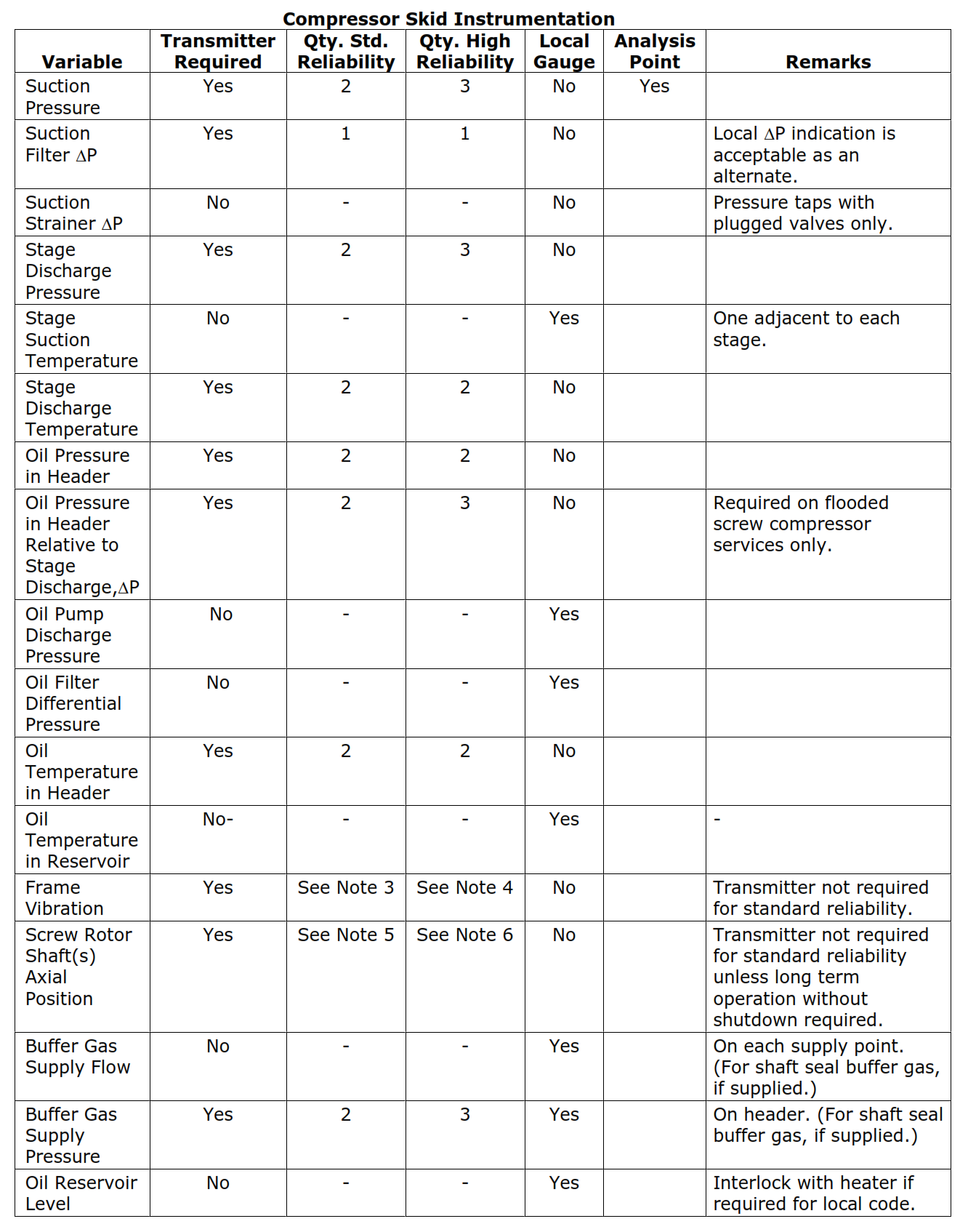
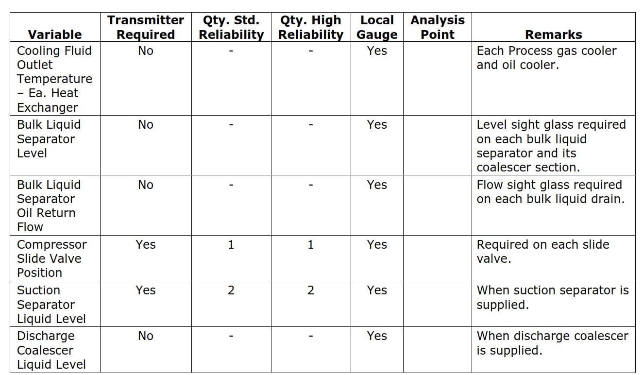
18.4 Instrumentation shall be provided as listed in Table 1 unless specified differently in the Project Technical Specification. Instrument quantities shall be provided in accordance with Table 1 based on the required project reliability (“Standard” or “High” reliability) as indicated in the project Technical Specification. All local instruments and electrical equipment shall be wired to NEMA 4X (or IEC equivalent IP 56) junction boxes provided by the supplier and located at the skid edge. Separate junction boxes, or one junction box with separate terminal rails, shall be provided for each signal type: analog signals (4–20 mA), digital signals, temperature signals, and trip signals, and for each type of protection (for example, intrinsically safe and explosion proof).
Table 1 – Compressor Skid Instrumentation
|
Variable |
Transmitter Required | Qty. Std. Reliability | Qty. High Reliability | Local Gauge | Analysis Point |
Remarks |
| Suction Pressure | Yes | 2 | 3 | No | Yes | |
| Suction Filter DP | Yes | 1 | 1 | No | Local DP indication is acceptable as an alternate. | |
| Suction Strainer DP | No | – | – | No | Pressure taps with plugged valves only. | |
| Stage Discharge Pressure | Yes | 2 | 3 | No | ||
| Stage Suction Temperature | No | – | – | Yes | One adjacent to each stage. | |
| Stage Discharge Temperature | Yes | 2 | 2 | No | ||
| Oil Pressure in Header | Yes | 2 | 2 | No | ||
| Oil Pressure in Header Relative to Stage Discharge,DP | Yes | 2 | 3 | No | Required on flooded screw compressor services only. | |
| Oil Pump Discharge Pressure | No | – | – | Yes | ||
| Oil Filter Differential Pressure | No | – | – | Yes | ||
| Oil Temperature in Header | Yes | 2 | 2 | No | ||
| Oil Temperature in Reservoir | No- | – | – | Yes | – | |
| Frame Vibration | Yes | See Note 3 | See Note 4 | No | Transmitter not required for standard reliability. | |
| Screw Rotor Shaft(s) Axial Position | Yes | See Note 5 | See Note 6 | No | Transmitter not required for standard reliability unless long term operation without shutdown required. | |
| Buffer Gas Supply Flow | No | – | – | Yes | On each supply point. (For shaft seal buffer gas, if supplied.) | |
| Buffer Gas Supply Pressure | Yes | 2 | 3 | Yes | On header. (For shaft seal buffer gas, if supplied.) | |
| Oil Reservoir Level | No | – | – | Yes | Interlock with heater if required for local code. | |
| Cooling Fluid Outlet Temperature – Ea. Heat Exchanger | No | – | – | Yes | Each Process gas cooler and oil cooler. | |
| Bulk Liquid Separator Level | No | – | – | Yes | Level sight glass required on each bulk liquid separator and its coalescer section. | |
| Bulk Liquid Separator Oil Return Flow | No | – | – | Yes | Flow sight glass required on each bulk liquid drain. | |
| Compressor Slide Valve Position | Yes | 1 | 1 | Yes | Required on each slide valve. | |
| Suction Separator Liquid Level | Yes | 2 | 2 | Yes | When suction separator is supplied. | |
| Discharge Coalescer Liquid Level | No | – | – | Yes | When discharge coalescer is supplied. |
| Table 1 Notes:
1. Temperature transmitter requirements include the thermocouple or RTD, and wiring. 2. Analysis point refers to a thermowell for temperature and a valved connection for pressure. 3. For standard reliability casing-mounted vibration switch(es) shall be furnished as follows: A minimum of one switch is required and shall be mounted directly on each casing. Vibration switches shall be Robertshaw Model 366-A-8 with the space heater mounted in a Crouse-Hinds explosion-proof enclosure. The switch shall be furnished with a manual push-button reset and without a time delay feature. Crouse-Hinds box and Robertshaw vibration switch shall be mounted to the casing in a rigid manner. 4. For high reliability casing-mounted vibration transmitter(s) shall be furnished as follows: A minimum of two or four transmitters are required and shall be mounted directly on each casing (see paragraph 17.2.3). Vibration transmitters shall be Metrix Model 5484C-121 (or approved equal) with 4-20 mA output signal. 5. For long term operation without compressor shutdown axial position probes and transmitter(s) shall be furnished as follows: A minimum of one probe and transmitter per thrust bearing are required (See paragraph 17.2.5.) Axial Position transmitters shall be Metrix Model 5488 (or approved equal) with 4-20 mA output signal. 6. For high reliability axial position probes and transmitter(s) shall be furnished as follows: A minimum of three (or two if three not possible) transmitters per thrust bearing are required (see paragraph 17.2.6). Axial Position transmitters shall be Metrix Model 5488 (or approved equal) with 4-20 mA output signal. |
19. SUCTION SEPARATOR
19.1 When specified in the Project Technical Specification, a process gas suction separator shall be supplied as part of the compressor skid. The separator shall be mounted on the compressor skid and completely piped to include piping to compressor suction and all instrument and drain lines.
19.2 Unless specified in the Project Technical Specification, the vessel pressure rating shall be the same as the process suction of the compressor.
19.3 Instrumentation for the separator shall be supplied per Table 1.
19.4 Unless specified in the Project Technical Specification, the separator drain piping shall be supplied with a manual drain valve piped to skid edge.
19.5 A reflex type liquid level gauge shall be supplied with gauge cocks, isolation valves, drain valve, and gauge support bracing.
19.6 Unless specified in the Project Technical Specification, the suction separator shall be sized to normally run without a liquid level and shall include a gas exit demister separator such as a mesh pad. The supplier shall submit for Purchaser’s approval the sizing criteria for the vessel diameter and the gas exit demister separator. The separator shall include a minimum of 20 liters (5 gallons) inventory between 20% and 80% of the alarm and shutdown liquid level range.
19.7 A safety relief valve sized per the criteria in Section 13.5 shall be supplied at the suction separator if the vessel can be isolated and is not protected per applicable piping/vessel codes.
19.8 For wet gas service, insulation and heat tracing in accordance with applicable specifications in Section 3.1 may be necessary on the vessels and piping.
20. RECEIVER BULK LIQUID COOLANT SEPARATOR
20.1 A combination receiver bulk liquid coolant separator shall be furnished with oil or water flooded screw compressor packages to separate the coolant/lubricant liquid from the compressor discharge gas. The liquid content in the process gas leaving the separator shall be less than 10 ppm (parts per million) by weight.
20.2 The receiver-separator shall be positioned at the proper elevation to control the oil level in the liquid sump and prevent excess flooding of the compressor. It is preferred that the compressor main discharge piping be free draining to the receiver-separator without any liquid traps.
20.3 The receiver-separator oil retention time and oil pump suction piping design shall be sufficient to prevent detrimental entrained or dissolved process gas in the oil that will cause oil pump suction cavitation and/or long term oil pump and compressor bearings and rotor damage.
20.4 An oil heater shall be provided per paragraph 15.12.
20.5 The reservoir-separator shall have a cleanable sight glass liquid level indicator with shutoff valves and a connection for a safety valve.
20.6 Lubricant make-up is to be minimized. Bulk liquid drainage from the separator(s) shall be continuously returned to the compressor suction for re-use in process gas applications where the lubricant is not degraded or contaminated by the process gas or condensates.
20.7 When specified in the Project Technical Specification for flooded screw compressors, a permanent lubricant makeup motor driven charging pump shall be supplied and piped on the skid. Lubricant makeup shall be pumped into the compressor suction. The makeup charging line shall include a root block valve (at the compressor suction line), strainer, check valve, and charging pump discharge block valve, and pump discharge safety valve. The pump suction shall include an NPT connection.
21. CONDENSATE LIQUID SEPARATOR – OIL COALESCERS
21.1 When provided, condensate liquid separators shall remove a minimum of 90% of the free liquid in the gas at the separator temperature and pressure operating conditions. The separator shall be sized for a minimum of 4 liters (1 gallon) retention between the sight glass high and low level liquid elevations.
21.2 When specified in the Project Technical Specification, an oil coalescer shall be supplied at the discharge of the skid. The coalescer shall be capable of operating with 5 ppmv or less of liquid in the discharge gas. The coalescer shall be provided in accordance with the following:
21.2.1 The coalescer vessel(s) shall be provided with Balston DX/BX, Monsanto CGF or Pall Trincor Seprosol Plus coalescing elements. When height requirements of coalescer vessels are limited or the maximum flow rate is too small, up-flow type elements (that is, Balston DX elements in the first‑stage housing and Balston BX elements in the second-stage housing) or Air Products approved equivalent may be used instead. Up-flow (Balston type) elements are 61 mm (2.4 in) outer diameter by 476 mm (18.75 in) element length. As such, they require in most cases numerous elements inside a vessel. In no case shall up-flow type elements be used when more than 24 elements are required in a stage vessel.
21.2.2 Each stage coalescer shall be provided in an individual vessel. These vessels are to be piped in series flow. Supplier shall advise the vessel wall thickness and method of radiography used.
21.2.3 Vessels shall be sized so that the maximum allowable velocity through the net up-flow area (after accounting for area occupied by the elements) should not exceed that corresponding to a Kv = 0.25 ft/sec for Up-flow Type Elements and a Kv = 0.60 ft/sec for Monsanto or Pall elements where:
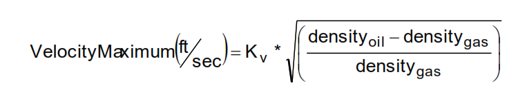
Note: Densities are at operating conditions.
21.3 Elements shall be selected such that the outer face velocity at the maximum operating flow condition does not exceed 0.076 m/sec (15 ft/min) for solid core elements and 0.152 m/sec (30 ft/min) for pleated elements. The surface area shall be calculated from the projected outer diameter of the element.
21.4 Up-flow type element vessels shall have inlet and outlet connections located along with baffling to ensure even gas flow through all elements. The gas flow path between the vessel inlet and outlet ports shall be from inside to outside through the coalescing element. Sufficient elements shall be provided so that outer face velocity of the elements does not exceed 0.05 m/s (10 ft/min). The oil removed by the elements shall drain by gravity to an oil sump in the bottom of each vessel to be bled from an oil drain port. Flow shall be such that gas passes upward past the top of the elements before it turns to exit the vessel. The gas discharge connection on the vessel shall be located above the top of the coalescer element and may be oriented as top or side discharge from the vessel.
21.5 Coalescer elements and their supports shall be able to withstand a 2.76 bar (40 psi) pressure differential in the normal flow direction and a 0.34 bar (5 psi) differential in the reverse flow direction without collapsing. Element mounting hardware shall be constructed of stainless steel. No corrosion allowance is required on stainless steel. Up-flow type elements and mounting hardware shall be removed for shipment.
21.6 All vessels for Monsanto coalescing elements shall have lifting lugs on their heads and no davit. All vessels for coalescers with up-flow type elements shall be furnished with a lifting davit. Davit(s) pivot point shall be fitted with a “zerk” type grease fitting.
21.7 Vessels (and upper vessel chamber using up-flow type elements) shall contain at least a 15 liter (4 gallon) sump capacity, without wetting filter elements.
21.8 Monsanto elements have a 99.99% efficiency for calculating aerosol removal. For Balston DX elements, use 93% efficiency to calculate aerosol removal and for Balston BX elements, use 99.99% efficiency to calculate aerosol removal. Pall SepraSol elements have a 99.95% efficiency for calculating aerosol removal.
21.9 Unless specified in the Project Technical Specification, the vessel pressure rating shall be the same as the process discharge of the compressor.
21.10 Instrumentation for the coalescer shall be supplied per Table 1.
21.11 Unless specified in the Project Technical Specification, the coalescer drain piping bottom sump shall be supplied with individual drains from the bottom sump and the top of the coalescer tubesheet (if used). This drain shall be piped to return to compressor suction where the lubricant is not degraded or contaminated and each line shall include manual drain valves, check valves, and strainers.
21.12 A reflex type liquid level gauge shall be supplied on each coalescer’s vessel with gauge cocks, isolation valves, drain and vent valves, and gauge support bracing.
SPECIAL TOOLS
22.1 One complete set of all special tools shall be provided with each compressor. When hydraulic tensioned fasteners are incorporated in the compressor design, hydraulic tensioning tools shall be included. When more than one compressor, up to a maximum of three, is supplied at one location, one set of special tools per location shall be acceptable. When a supplier’s construction superintendent services are contracted, it shall be the responsibility of this individual to ensure that one complete set of special tools is on hand at any one location before leaving the site.
INSPECTION AND TESTING
23.1 Air Products’ extent of participation in inspection and testing is detailed in Appendix A, Quality Control Plan, Principle Stages of Inspection.
23.2 In principle, the maximum amount of testing of the compressor and ancillary equipment is required before dispatch from the supplier’s works. However, the extent of testing will vary greatly depending on the process duty for the compressor and the physical size of the compressor and auxiliaries. The supplier’s quotation shall state clearly the extent of testing possible and detail the tests included in the quotation.
23.3 The compressor supplier’s standard shop mechanical and performance testing shall be included as a minimum for the bare compressor casing unless additional testing is specified in the Project Technical Specification. The packager’s quotation shall state clearly the compressor supplier’s standard shop testing scope and performance data correction procedure to correct to contract conditions specified herein.
23.4 The completed compressor package and lube oil system shall be pressure tested at the packager’s facility after assembly.
23.5 When specified in the Project Technical Specification a four-hour mechanical run test of the compressor and its lube oil system shall be performed in the supplier’s shop. The contract lube oil console shall be used for oil- or water-flooded screw compressor packages. This may be done at the packager’s fabrication site.
23.6 After installation in the field, Air Products reserves the right to perform a compressor performance test using ASME PTC 9 or VDI 2045 as a guideline. This will only be necessary if operating data shows that the performance is not as specified. The field test procedure specific to screw compressors using ASME PTC 9 or VDI 2045 as a guideline for development will be written by Air Products and reviewed by the supplier. Compressor power shall be based on motor efficiency and motor terminal power measured by the two watt meter method or a kilowatt hour meter. Any modifications required to meet guarantees shall be made by the supplier at no cost to Air Products. Any subsequent tests will be performed by the supplier at no cost to Air Products.
23.7 The interior of equipment shall meet the inspection and acceptance requirements of 4WPI‑SW70001.
PAINTING AND PREPARATION FOR SHIPMENT
24.1 The compressor and all auxiliaries shall be painted according to the supplier’s high temperature corrosion-resistant paint system. A copy of this procedure shall be provided as part of the equipment records unless it has been previously reviewed and approved by Air Products. Mass-produced equipment such as filter, switches, small motors, small pumps, and small coolers shall be purchased with the supplier’s standard preparation and finish paint system.
24.1.1 All other exterior ferrous material surfaces shall be cleaned and painted. The cleaning and painting requirements are outlined in paragraphs 24.1.1 thru 24.2.6.
Surface preparations shall be shot or sandblast cleaning, pickling, or power tool cleaning, removing all millscale, rust, weld slag, and weld splatter to provide a surface suitable for prime coating according to paint supplier’s recommendations.
24.1.2 Primer paint shall be supplier’s standard. One or more coats shall be applied to achieve 0.08 mm (0.003 in) minimum dry film thickness. Surfaces in contact with epoxy grout shall be primer painted only with Carboline Carbozinc-11 or other epoxy topcoat compatible primer.
24.1.3 Finish paint shall be supplier’s standard. One or more coats shall be applied to achieve 0.04 mm (0.0015 in) minimum dry film thickness. The total dry film thickness of primer and finish coat shall be 0.12 mm (0.0045 in) minimum.
24.2 Painting workmanship shall be as follows:
24.2.1 Cleaned surfaces shall receive the first prime coat within eight hours after cleaning. If uncoated for a longer period, recleaning is required.
24.2.2 Surfaces shall be free of visible moisture immediately before and after painting until the paint is dry to the touch. Ambient and work surface temperatures shall be between 13°C
and 52°C (55°F and 125°F) for epoxy systems and between 5oC and 52oC (40°F and
125°F) for other paint systems.
24.2.3 Paint shall be applied according to the paint supplier’s printed directions pertinent to thinning, stirring, drying time, and priming requirements.
24.2.4 Each coat shall be unscarred, free of dirt, and completely adhering without any defect at time of applying succeeding coat. A smooth, uniform color and finish is required.
24.2.5 Underthickness areas shall receive additional coats as required to achieve the required thickness all over.
24.2.6 Painted material shall be dry before loading and shall be handled and blocked with care to minimize paint damage.
Note: The supplier shall provide 4 liters (1 gallon) of finish paint with the compressor for field touch-up.
24.3 When painted, interior surfaces of the gas passages shall be furnished with the supplier’s standard preparations and paint system. Aluminum-based paint shall not be used on interior surfaces that come into contact with fuel gas or natural gas.
24.4 Unless otherwise specified in the Project Technical Specification, all packing and preparation for shipment shall be according to 4WGN-10001 with the following exceptions:
24.4.1 Any reference to oxygen clean is not applicable.
24.4.2 The information required shall be sent to the Air Products shipping group in Hersham, England for projects executed in Europe and to Allentown for projects executed in the U.S.
TAGGING, LANGUAGE, AND UNITS
25.1 All manually operated valves, automatic valves, and locally mounted instruments shall be tagged with numbers provided by Air Products.
25.2 The tags shall be noncorroding and large enough to include all of the digits of an item’s tag number. Each tag shall be fixed adjacent to the item or alternatively, securely attached to the item with a wire made of a corrosion-resistant material such as stainless steel. The wire shall be at least 1 mm thick. The wire shall be secured by twisting it around some part of the device from which it will not slide off. The tag and wire shall not hinder in any way the operation of the device to which they are attached.
25.3 Equipment having items such as, code nameplates shall have the tag numbers stamped on the nameplate. The nameplates shall be positioned such that they can be easily read.
25.4 The language used on all nameplates, drawings, and documentation shall be English and in the language of the country in which the machine will be operating unless otherwise specified in the Project Technical Specification.
25.5 All dimensions and physical units shall be in dual units (including pressure) unless otherwise specified in the Project Technical Specification.
DRAWINGS AND INFORMATION
26.1 The supplier shall submit the drawings and data as specified in the Drawing Requirements Documents attached to the Project Technical Specification and/or detailed with the Purchase Order.
26.2 A Material Safety Data Sheet (MSDS) for all components (other than products and byproducts) associated with the equipment being assembled, sold, or provided shall be compiled during purchase, fabrication, and assembly. An MSDS shall be provided for all of the following typical materials that are not permanently fixed to the equipment, but are removable or replaceable and could create a hazardous exposure to employees involved in the installation, operation, or maintenance of the equipment:
- Gasket and O-ring materials.
- Grouting and cements used in assembly.
- Machinery and valve lubricants, and valve packing/ring materials.
- Protective coatings and coverings.
The MSDS obtained from the suppliers of equipment or sub-parts shall be requested to be provided in the English language and shall be submitted to Air Products.
PROPOSALS
27.1 Supplier shall submit the specified number of complete sets of proposals that shall include the following data and drawings, in addition to the information required by the request for quotation:
Completed API STD 619 Screw Compressor Data Sheets – Metric or U.S. Customary Units as indicated in the Project Technical Specification
Complete list of exceptions taken to the specification.
Supplier’s testing capabilities.
Preliminary general arrangement drawing including all mounted equipment.
Typical cross section drawing of compressor and running gear.
Completed supplier drawing and data requirements sheet with promised delivery dates.
27.2 The supplier shall provide a priced list of start-up and commission spare parts. In addition, the supplier shall provide a priced list of capital spare parts included in Table 2.
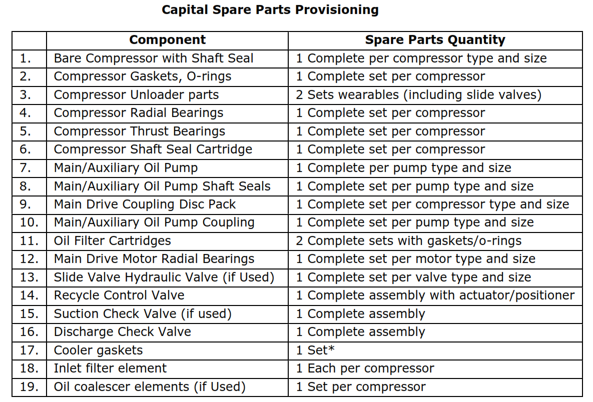
Table 2
Capital Spare Parts Provisioning
Component |
Spare Parts Quantity | |
| 1. | Bare Compressor with Shaft Seal | 1 Complete per compressor type and size |
| 2. | Compressor Gaskets, O-rings | 1 Complete set per compressor |
| 3. | Compressor Unloader parts | 2 Sets wearables (including slide valves) |
| 4. | Compressor Radial Bearings | 1 Complete set per compressor |
| 5. | Compressor Thrust Bearings | 1 Complete set per compressor |
| 6. | Compressor Shaft Seal Cartridge | 1 Complete set per compressor |
| 7. | Main/Auxiliary Oil Pump | 1 Complete per pump type and size |
| 8. | Main/Auxiliary Oil Pump Shaft Seals | 1 Complete set per pump type and size |
| 9. | Main Drive Coupling Disc Pack | 1 Complete set per compressor type and size |
| 10. | Main/Auxiliary Oil Pump Coupling | 1 Complete set per pump type and size |
| 11. | Oil Filter Cartridges | 2 Complete sets with gaskets/o-rings |
| 12. | Main Drive Motor Radial Bearings | 1 Complete set per motor type and size |
| 13. | Slide Valve Hydraulic Valve (if Used) | 1 Complete set per valve type and size |
| 14. | Recycle Control Valve | 1 Complete assembly with actuator/positioner |
| 15. | Suction Check Valve (if used) | 1 Complete assembly |
| 16. | Discharge Check Valve | 1 Complete assembly |
| 17. | Cooler gaskets | 1 Set* |
| 18. | Inlet filter element | 1 Each per compressor |
| 19. | Oil coalescer elements (if Used) | 1 Set per compressor |
*For up to three identical compressors at one location.
Appendix A Quality Control Plan
Principal Stages of Inspection
| Drawn: Approved: | Inspection by: | Scope of Inspection: | ||||||
| AP = Air Products or Nominee | H = Mandatory Hold Point | |||||||
| IA = Independent Authority | IA = Inspection Scope as | |||||||
| Item: Screw | Client = Customer or Nominee | Required by IA | ||||||
| Compressor Package | L1 = 100% Inspection | |||||||
| L2 = Random Inspection | ||||||||
| R1 = 100% Document Review | ||||||||
| R2 = Sample Document Review | ||||||||
| Action
Number |
Activity |
Scope of Inspection
AP IA Client |
Check Documents
or Procedures |
Additional
Information |
||||
| Index Sheet | Sheet 1 | |||||||
| Bare Compressor | Sheet 2 | |||||||
| Intercooler and Aftercooler | Sheets 3 and 4 | |||||||
| Process Piping | Sheet 5 | |||||||
| Lube Oil System | Sheet 6 | |||||||
Dwg. No. Q5000-5500c Rev. 0. Sheet 1 of 6
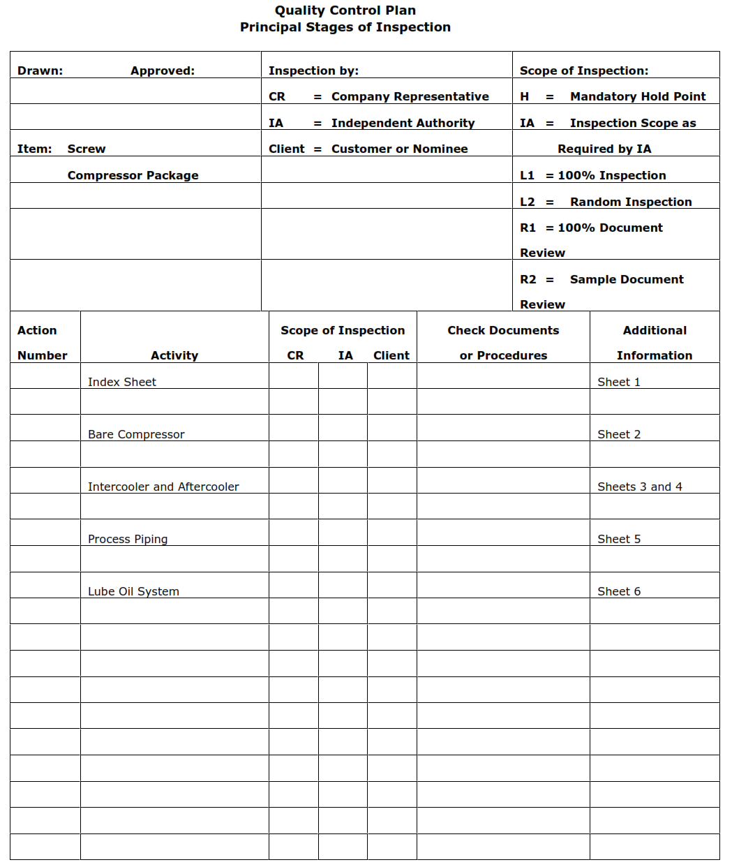
Appendix A (continued)
| Drawn: Approved: | Inspection by: | Scope of Inspection: | ||||||
| AP = Air Products or Nominee | H = Mandatory Hold Point | |||||||
| IA = Independent Authority | IA = Inspection Scope as | |||||||
| Item: Screw | Client = Customer or Nominee | Required by IA | ||||||
| Compressor Package— | L1 = 100% Inspection | |||||||
| Bare Compressor | L2 = Random Inspection | |||||||
| R1 = 100% Document Review | ||||||||
| R2 = Sample Document Review | ||||||||
| Action
Number |
Activity |
Scope of Inspection
AP IA Client |
Check Documents
or Procedures |
Additional
Information |
||||
| 1. | Review and Approve Quality Plan |
R1 | AP purchase order and referenced specifications |
|||||
| 2. | Hydrostatic Test of Pressure Containing Components | R1 | ||||||
| 3. | Visual and dimensional for conformance to specification | L1 | ||||||
| 4. | Combined mechanical and performance test | L1 | Supplier standard performance test may be accepted | |||||
| 5. | Cleanliness Inspection | L2 | AP specification 4WPI-SW70001 |
|||||
| 6. | Inspection and Dimensional Check of the Total Assembly |
L1 | Approved drawings | |||||
| 7. | Review Certification and Test Data |
R1 | Same as Action Number 1 |
Including certificates for NDT | ||||
| 8. | Check Preservation and Packing Before Shipment | L1 | ||||||
Dwg. No. Q5000-5210 Rev. 1. Sheet 2 of 6
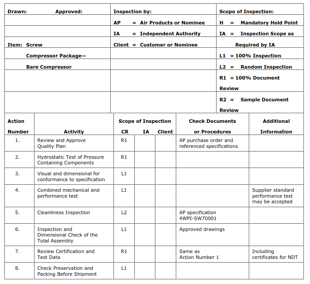
Appendix A (continued)
| Drawn: Approved: | Inspection by: | Scope of Inspection: | ||||||
| AP = Air Products or Nominee | H = Mandatory Hold Point | |||||||
| IA = Independent Authority | IA = Inspection Scope as | |||||||
| Item: Screw | Client = Customer or Nominee | Required by IA | ||||||
| Compressor Package— | L1 = 100% Inspection | |||||||
| Intercooler and Aftercooler | L2 = Random Inspection | |||||||
| R1 = 100% Document Review | ||||||||
| R2 = Sample Document Review | ||||||||
| Action
Number |
Activity |
Scope of Inspection
AP IA Client |
Check Documents
or Procedures |
Additional
Information |
||||
| 1. | Design Approval | R1 | IA | Inspection test and | ||||
| 2. | Review and Approve Quality Plan |
R1 | IA | acceptance criteria in accordance with | ||||
| 3. | Welding Procedure Specification | R1 | IA | WPS | the referenced code requirements | |||
| 4. | Welding Procedure Approval Record | R1 | IA | WPAR (formerly PQR) | ||||
| 5. | Welder Approval Test Certificate |
R1 | IA | WPQ | ||||
| 6. | Identify Material, Check Certification |
L2 | IA | Material certificates | ||||
| 7. | Check Weld Preparation and Fit Up | L2 | IA | WPS | ||||
| 8. | Check Radiographs and Other NDE | R1 | IA | Radiograph and NDE reports | ||||
| 9. | Visual and Dimensional Checks Before Insertion of Bundle Into Shell | L1 | IA | AP specification 4WEQ-1430 and 4WPI-SW70001; approved drawings | Including bundle, shell and channel ends | |||
| 10. | Check Insertion of Bundle Into Shell | H | ||||||
| 11. | Pressure Test Shell Side | R1 | H | Code | ||||
| 12. | Pressure Test Tube Bundle | R1 | H | Code | ||||
| 13. | Leak Test Shell Side | H | ||||||
| 14. | Leak Test Tube Side | H | ||||||
| 15. | Check Cleanliness | L2 | ||||||
Dwg. No. Q5000-5500c Rev. 0. Sheet 3 of 6
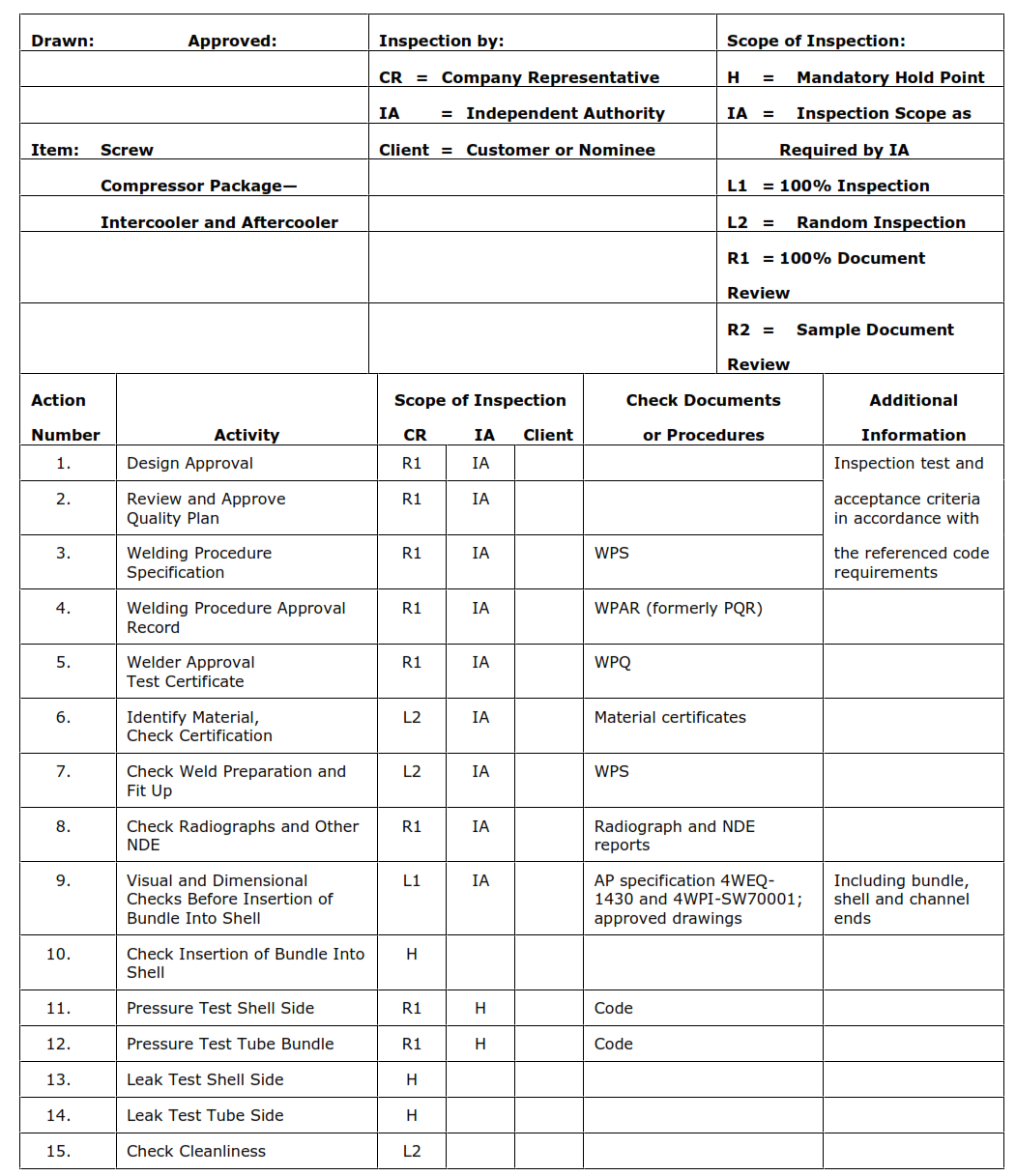
Appendix A (continued)
| Drawn: Approved: | Inspection by: | Scope of Inspection: | ||||||
| AP = Air Products or Nominee | H = Mandatory Hold Point | |||||||
| IA = Independent Authority | IA = Inspection Scope as | |||||||
| Item: Screw | Client = Customer or Nominee | Required by IA | ||||||
| Compressor Package— | L1 = 100% Inspection | |||||||
| Intercooler and Aftercooler | L2 = Random Inspection | |||||||
| (continued) | R1 = 100% Document Review | |||||||
| R2 = Sample Document Review | ||||||||
| Action
Number |
Activity |
Scope of Inspection
AP IA Client |
Check Documents
or Procedures |
Additional
Information |
||||
| 16. | Check Name Plate Date and Stamp |
L1 | H | Approved drawings | ||||
| 17. | Final Inspection Including Painting | L1 | IA | As Action Number 9 plus referenced paint specification | ||||
| 18. | Review Dossier and Approve |
R1 | H | |||||
| 19. | Check Preparations for Shipment | L2 | Including blanking of nozzles and shipping charge | |||||
Dwg. No. Q5000-5500c Rev. 0. Sheet 4 of 6
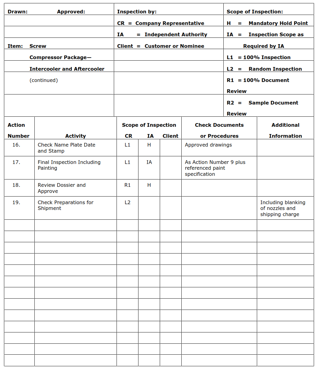
Appendix A (continued)
| Drawn: Approved: | Inspection by: | Scope of Inspection: | ||||||
| AP = Air Products or Nominee | H = Mandatory Hold Point | |||||||
| IA = Independent Authority | IA = Inspection Scope as | |||||||
| Item: Screw Compressor | Client = Customer or Nominee | Required by IA | ||||||
| Compressor Package— | L1 = 100% Inspection | |||||||
| Process Piping | L2 = Random Inspection | |||||||
| R1 = 100% Document Review | ||||||||
| R2 = Sample Document Review | ||||||||
| Action
Number |
Activity |
Scope of Inspection
AP IA Client |
Check Documents
or Procedures |
Additional
Information |
||||
| 1. | Review Welding Procedure Specification | R1 | IA | WPS | If piping is classified, fabrication, inspection, and | |||
| 2. | Check Welding Procedure Approval Record | R1 | IA | WPAR (formerly PQR) | testing to be in accordance with code requirements | |||
| 3. | Check Welder Approval Test Certificate | R1 | IA | WPQ | ||||
| 4. | Identify Material, Check Certification |
R2 | IA | Material certificates | ||||
| 5. | Review NDE and Radiography Films |
R1 | IA | Radiographs and NDE reports | ||||
| 6. | Cleanliness Checks | L2 | Referenced AP specification 4WPI-SW70001 |
|||||
| 7. | Inspect Painting | L2 | Referenced paint specification | |||||
| 8. | Review Certification | R1 | IA | |||||
Dwg. No. Q5000-5500c Rev. 0. Sheet 5 of 6
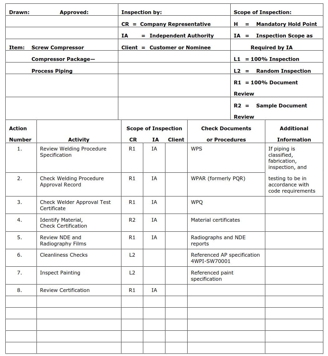
Appendix A (continued)
| Drawn: Approved: | Inspection by: | Scope of Inspection: | |||||||
| AP = Air Products or Nominee | H = Mandatory Hold Point | ||||||||
| IA = Independent Authority | IA = Inspection Scope as | ||||||||
| Item: Screw | Client = Customer or Nominee | Required by IA | |||||||
| Compressor Package— | L1 = 100% Inspection | ||||||||
| Lube Oil System | L2 = Random Inspection | ||||||||
| R1 = 100% Document Review | |||||||||
| R2 = Sample Document Review | |||||||||
| Action
Number |
Activity |
Scope of Inspection
AP IA Client |
Check Documents
or Procedures |
Additional
Information |
|||||
| 1. | Hydraulic Test of Lube Oil System Components | R1 | AP purchase order and referenced specifications | ||||||
| 2. | Check Overall Dimensions and Piping Termination | L1 | Approved arrangement drawing | ||||||
| 3. | Check Scope of Supply Against P & ID | L1 | Approved P & ID | ||||||
| 4. | Witness Two- or Four-Hour Run Including: | L1 | Approved test procedure | May be combined with run test of compressor | |||||
| 4.1 | Check on Relief Valve Setting | L1 | |||||||
| 4.2 | Check on All Control Devices | L1 | |||||||
| 4.11 | Check on Cooler/Filter Change Over | L1 | |||||||
| 4.4 | Cleanliness Check | L1 | |||||||
| 5. | Inspect Painting | L1 | Referenced paint specification | ||||||
| 6. | Review Test Data | R1 | |||||||
| 7. | Review Dossier | R1 | Including documentation and certification for pump, auxiliary pump and motor (if fitted), coolers and heater | ||||||
| 8. | Check Preservation and Packing Before Shipping |
L1 | |||||||
Dwg. No. Q5000-5500c Rev. 0. Sheet 6 of 6