SSR (Secondary Surveillance Radar) and IFF (Identification Friend or Foe) are often used interchangeably, as they refer to the same technology and concept in aviation.
What is Secondary Surveillance Radar (SSR)?
The IFF (Identification Friend or Foe) system is indeed a crucial component of military aviation, allowing friendly forces to distinguish themselves from potential threats. The IFF system is used by military forces to identify friendly aircraft and distinguish them from potential enemies. It operates by emitting electromagnetic signals that prompt equipped friendly aircraft to respond, thereby confirming their identity.
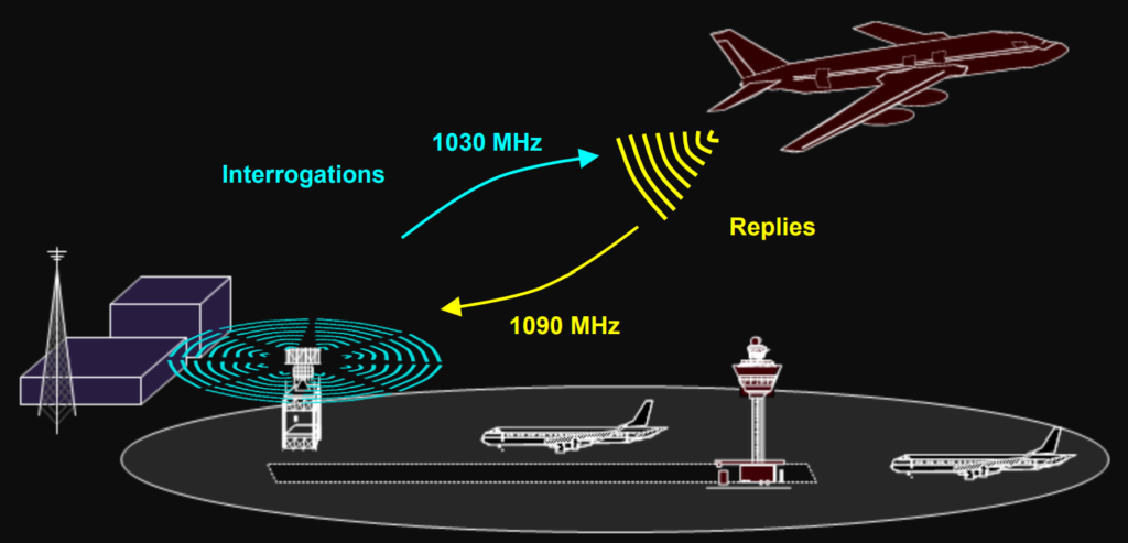
The SSR system, which is integral to modern Air Traffic Control (ATC), has its roots in the military IFF system developed during World War II. SSR works by sending out interrogations to aircraft equipped with transponders, which then reply with identifying information such as their altitude and assigned code.
Compatibility with Civilian Transponder Systems: Modern military aircraft are equipped with IFF systems that are compatible with the civilian transponder systems used in ATC. This compatibility allows military aircraft to operate safely in civilian airspace and facilitates coordination between military and civilian air traffic control authorities.
Secondary Surveillance Radar (SSR) Purpose.
The primary purpose of the SSR system is to locate, separate, and identify aircraft. This involves employing radar-like techniques to determine the aircraft’s location and employing communication-like techniques to identify and differentiate between aircraft.
Radar-Like Techniques:
- Directional Antenna: The system utilizes directional antennas to broadcast interrogations (requests for information) and receive replies from aircraft.
- Time of Transmission-Return: By measuring the time it takes for the transmitted signal to return, the system can calculate the range (distance) to the aircraft.
- Direction of Antenna: The azimuth (horizontal angle) of the antenna is used to determine the direction from which the aircraft’s signal is coming, aiding in locating the aircraft.
Communication-Like Techniques:
- Aircraft Responses: When interrogated, aircraft equipped with transponders respond with identifying data, including information such as aircraft altitude. This aids in identifying and separating aircraft.
- Cryptography: Military aircraft use cryptography (encryption) to transmit identification signals, ensuring that only authorized parties can decipher the identification data.
- Cooperative System Requiring Transponders: The system operates on a cooperative basis, requiring all aircraft to be equipped with transponders. These transponders respond to interrogations from ground-based systems, enabling aircraft identification. Strict adherence to communication protocols is necessary to ensure interoperability between different systems.
 Purpose.")
Equipment of ATC and IFF Examples.
Secondary Surveillance Radar (SSR) is a radio direction system used for aircraft surveillance. It works by comparing reference signals with radio signals retransmitted from the aircraft whose position is being determined.
The primary component of SSR is the transponder, which is an IFF/SSR beacon transmitter-receiver installed in aircraft. The transponder receives signals from an interrogator and selectively replies with a specific pulse group (code) only to those interrogations received on the mode to which it is set.
The Interrogator is the device responsible for generating a transmission of a signal or combination of signals intended to trigger a response from a Transponder. Essentially, it’s a station or device that requests another station or device (the transponder) to identify itself or provide its status. In the context of SSR, the interrogator sends out signals to aircraft transponders, prompting them to transmit identification and other relevant information back to the ground station. This information is then used by air traffic control for aircraft surveillance and management.

- Telephonics Skysearch 3000 System.
- Telephonics Aerotrac System.
- Telephonics SFF-44 Small Form Factor Interrogator for Mobile Applications.
- ATC Facility.
- Civil Aircraft Transponder.
- Military Aircraft Transponder and Crypto Computer.
- Telephonics AN/UPX-44 Long Range Interrogator for Ground Applications.
- KIV-78 IFF Cryptographic Computer.
- KIV-77 IFF Cryptographic Computer.
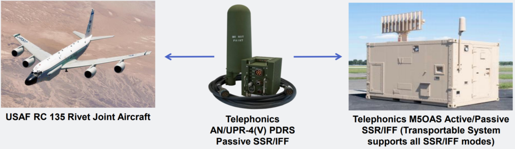
Multi-Band, Multi-Sector Passive IFF/SSR Detection and Reporting System (PDRS).
- The device described is a Passive Dependent Surveillance Receiver (PDRS), which receives transmissions from both Civil and/or Military transponder squitters and provides reports on aircraft 3D GPS position and other aircraft information.
- PDRS supports various ATC/IFF Modes, including Mode S Automatic Dependent Surveillance Broadcast (ADS-B), Universal Access Transceiver (UAT), and Military Mode 5 Level 2/Level 2B.
- For ground systems, the PDRS utilizes a multi-beam configuration with six multi-band antenna elements within the Radom. These elements are spaced 60 degrees apart in Azimuth, providing superior detection performance, greater surveillance range, anti-jam protection, and minimizing interference issues associated with Omni-directional antennas.
IFF/SSR Display.
The display used by air traffic controllers or military IFF (Identification Friend or Foe) operators to show target information, identify targets, and control the movement of aircraft is commonly referred to as a Radar Display or Radar Scope.

History of SSR and IFF.
Visual identification methods, such as flags, banners, and uniforms, served as the primary means of distinguishing between friendly and hostile forces for centuries. However, the advent of widespread aircraft usage during World War II introduced new challenges, as fast-moving threats made visual identification impractical in many situations.
The emergence of radar offered a promising solution by enabling the detection of incoming aircraft at a distance. However, early radar systems lacked the capability to identify the type of aircraft or determine their affiliation. This limitation was tragically illustrated during the attack on Pearl Harbor, where radar detected incoming Japanese aircraft but was unable to provide sufficient information for effective defense.
As a result, there was a growing recognition of the need for improved identification systems that could complement radar detection capabilities. This led to the development of IFF (Identification Friend or Foe) systems, which enabled aircraft to transmit identification signals that could be recognized by friendly radar installations. IFF technology revolutionized air defense by allowing operators to quickly distinguish between friendly and enemy aircraft, significantly enhancing situational awareness and response capabilities.
World War II.
Early in World War II, British pilots noticed something strange about German fighter planes. Sometimes, for no apparent reason, the German planes would suddenly roll over in flight.
After listening to radio signals, the British discovered that the German pilots were following a signal from the ground. When they rolled over, it changed how their planes appeared on German radar screens. This helped German radar operators know which planes were on their side.
This was one of the first attempts at an electronic IFF system. It involved sending a coded message (the radio signal) and getting a specific response (the plane rolling over).
The First Active IFF Systems.
The first German IFF maneuver was called a “passive system” because it relied on radar signals sent from the ground.
Around 1940, a more advanced system called the Mk I was introduced. Each aircraft had a receiver onboard that could transmit signals back when it detected radar signals.
The system was improved with the Mk III version, which included a separate transmitter. This transmitter was synchronized with the receiver and produced stronger signals when triggered. It could also be set to respond in different codes for better identification.
Further Refinements.
After World War II, there were many improvements in IFF systems, leading to the modern systems we have today. Modern IFF systems work like a question and answer game. An interrogator system sends out a coded radio signal asking, “Who are you?”
This signal is received by a device called a transponder on the target aircraft. If the transponder gets the right code, it automatically sends back the requested identification to the radar.
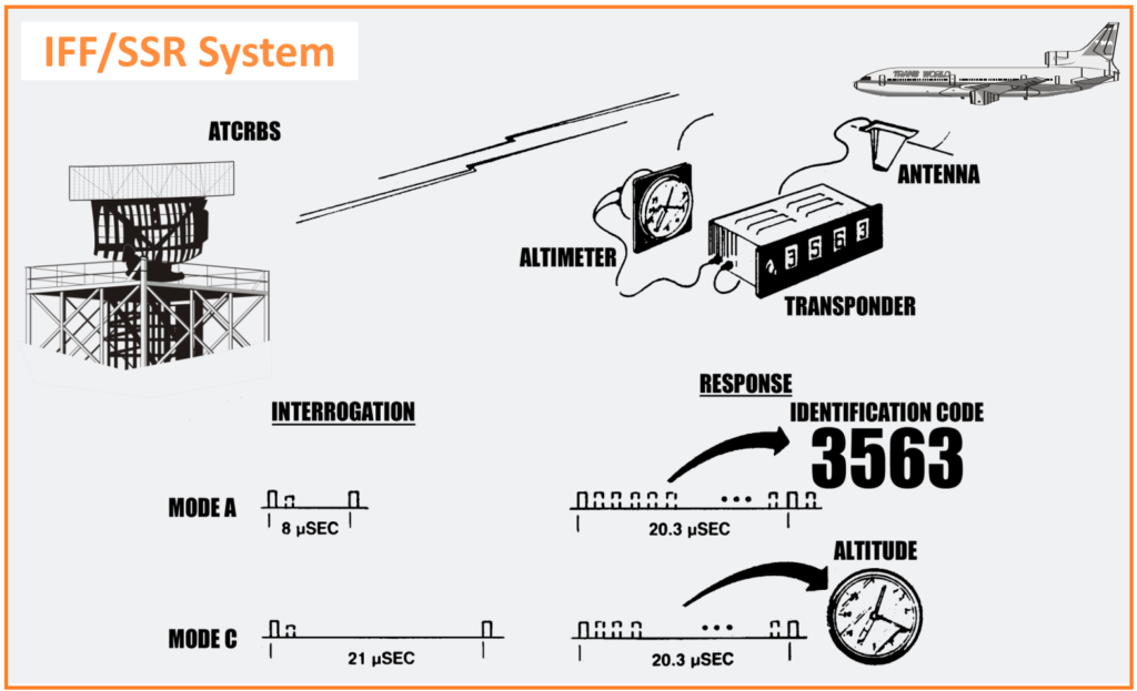
In the 1950s, the US Military introduced military IFF systems, including modes 1, 2, and 3, which were used for identification.
Introduction of SSR for Civilian ATC.
In the 1960s, civilian air traffic in the United States grew so much that air traffic controllers faced a big problem.
Their radar screens were getting crowded with blips from all the planes, and it was hard to tell which blip represented which aircraft. Plus, the radar couldn’t tell how high the planes were flying.
To solve this, a system similar to the military IFF systems was introduced for civilian air traffic control. It’s called the Air Traffic Control Radar Beacon System (ATCRBS). While the original purpose of IFF systems was to identify friendly forces in warfare, the civilian version is only used for identifying friendly aircraft.
For security reasons, there’s a special secure mode used by the military. This mode has extra safeguards to prevent hostile forces from pretending to be friendly. It uses secret codes and powerful encryption techniques to keep the identification secure.
The first secure IFF mode used by the US military was Mode 4, which was developed and put into use in the 1960s. Mode 4 required special computers with secret codes for both the interrogator and all the friendly transponders.
Improvements to Civilian SSR.
The SSR system used for Air Traffic Control (ATCRBS) had some weaknesses, especially with self-interference.
In the 1970s, the International Civil Aviation Organization (ICAO) started working on a new mode for civilian SSR called Mode S. The “S” stands for the primary new feature: the ability to selectively interrogate specific aircraft.
Although Mode S was defined in the 1970s, it took many years for full deployment. Europe adopted Mode S before the US did, requiring all aircraft, including general aviation, to have Mode S transponders by 2000.
In the 1990s, an automatic mode called ADS-B was developed. This mode used emerging GPS technology to broadcast aircraft GPS positions without needing interrogations. The US mandated that all aircraft be equipped with ADS-B by 2020.
Improvements to Military IFF.
In the 1990s, the US Military initiated the development of a new secure mode of IFF known as Mode 5. Recognizing the importance of collaboration, NATO joined as a full partner in this endeavor.
An initial specification for Mode 5 was released in 1997, followed by an updated version in 2003 to address significant issues identified in the original specification. Manufacturers have been deploying equipment since then, with the US and its Allies aiming for full operational capability by 2020.
Mode 5 addresses several shortcomings of Mode 4, such as resolving closely spaced targets and providing secure identification data. A sub-mode called Mode 5 Level 2 offers additional benefits by providing target GPS position data, which can be retrieved via an interrogation or automatically broadcast.
More recently, an extension of Mode 5 Level 2, known as Mode 5 Level 2 Bravo, has been defined. This variant offers cryptographically secured services similar to ADS-B. Prototypes of transponders with this capability have been developed and tested in flight.
Governing Documents.
Military.
SSR and IFF systems function as communication systems, requiring strict adherence to electronic protocols for the waveforms and data transmitted to ensure equipment interoperability. These protocols are outlined in several key documents:
- DoD AIMS Program Office:
- Document 65-1000: Defines Mark XII specifications for SIF and Mode 4.
- Document 97-1000: Initial definition of Mark XIIA, covering SIF, Mode 4, and Mode 5.
- Document 03-1000: Updated definition of Mode 5.
- Document 17-1000: Removed Mode 4 from requirements.
- Other documents provide additional requirements and guidance.
- NATO:
- STANAG 4193: Defines IFF specifications.
- Edition 2: Provided initial definition of Mark XIIA.
- Edition 3: Updated definition and reconciled differences between STANAG 4193 and AIMS 03-1000.
Civil.
ICAO (International Civil Aviation Organization) provides specifications for civilian SSR systems:
- ICAO Annex X, Volumes 3 & 4: Define civilian Mode 3/A, C, and S.
- Additional documents, such as 9871, define ADS-B.
RTCA (Radio Technical Commission for Aeronautics) offers further guidance for transponders:
- DO-260: Defines transponder minimum operational parameters (MOPS).
- DO-282: Defines Universal Access Transceiver (UAT) operation.
EUROCONTROL, the European Civil Aviation Organization, contributes:
- ASTERIX: Common interface specifications for air traffic control radars.
- Mode S Ground Station: A complete specification for a Mode S ATC radar, including Mode S clustering.
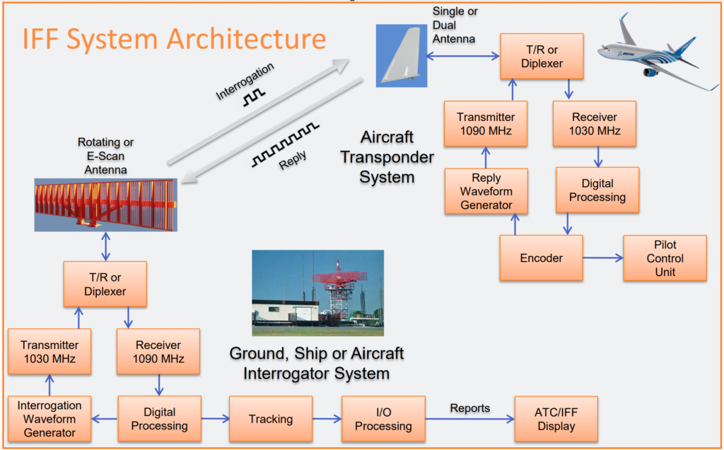
SSR/IFF System Architecture.
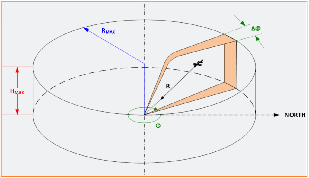
Scanning the Airspace.
Fan-Shaped Beam.
Defined for a target with an azimuth angle, Φ (relative to north), and a slant range, R” means that the target’s position is described by two parameters.
Sweep Versus Scan.
In IFF/SSR systems:
- A “sweep” refers to the distance covered from zero range to the maximum range.
- The “sweep time” or “Pulse Repetition Interval (PRI)” is the time interval between successive IFF/SSR interrogations.
- Typically, this interval ranges from 2.2 to 6.6 milliseconds, depending on the system’s range requirements.
- A “scan” represents a complete 360-degree revolution of the antenna.
- This scanning process typically takes from one (1) to twelve (12) seconds, depending on the system’s update requirements.
- Note: For those familiar with Primary Radar:
- When you “sweep” a floor, you don’t do it by swinging the broom in circles; instead, you move the broom in a straight line motion.
- When you “scan” the horizon, you don’t keep your head looking out in one direction; instead, you scan azimuthally, covering all directions.

Range.
The range of a target is determined by measuring the time between the interrogation reference pulse (P3 for SIF) and the time of receipt of the first framing pulse (F1) of the reply, minus the turnaround time of the transponder. It’s important to note that one (1) Nautical Mile (NM) equals 12.359 microseconds. This conversion factor is used in calculating distances in nautical miles based on time measurements.

Azimuth.
There are two methods for determining target azimuth: the beam split method and the monopulse method.
- The beam split method divides the received signal into multiple beams and analyzes their relative strengths to determine azimuth.
- The monopulse method, which is about five times more accurate, uses a single antenna to measure azimuth based on the phase or amplitude differences of received signals.
Both methods will be explained in detail later in the article.

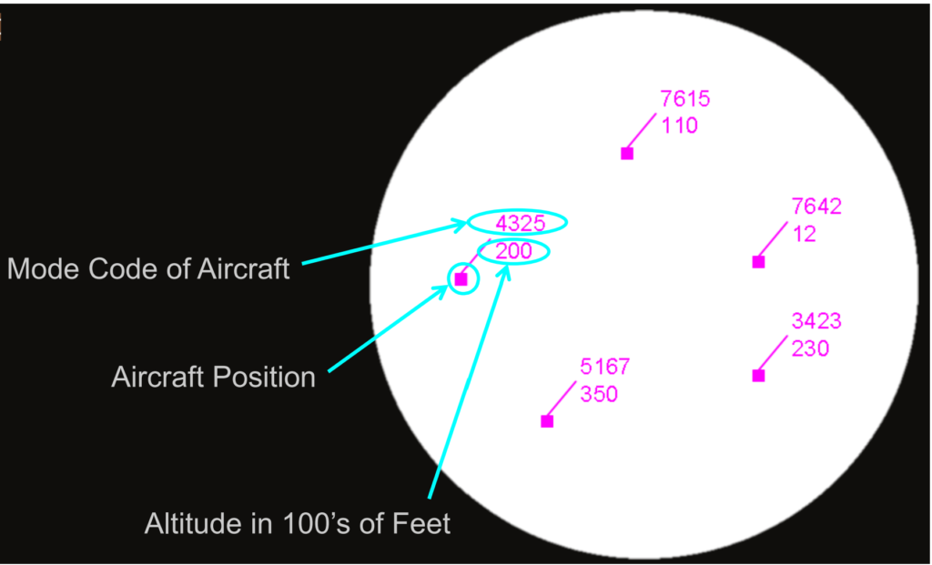
Code (ABCD)/Altitude (x100 Ft) Reporting.
The operator ultimately sees a code (ABCD) representing the aircraft’s identification or status and the altitude, expressed in hundreds of feet (x100 Ft).
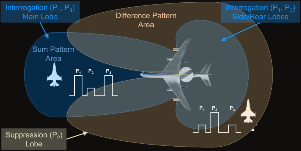
Sidelobe Suppression.
Sidelobe suppression refers to the technique used to reduce or minimize the strength of sidelobes in radar or antenna systems. Sidelobes are unwanted secondary lobes or radiation patterns that occur alongside the main lobe of the antenna’s radiation pattern. Suppressing these sidelobes helps improve the accuracy and efficiency of the radar system by reducing interference from signals coming from directions other than the intended target direction.
There are two types of sidelobe suppression.
- ISLS: Interrogator Sidelobe Suppression.
- RSLS: Receiver Sidelobe Suppression.
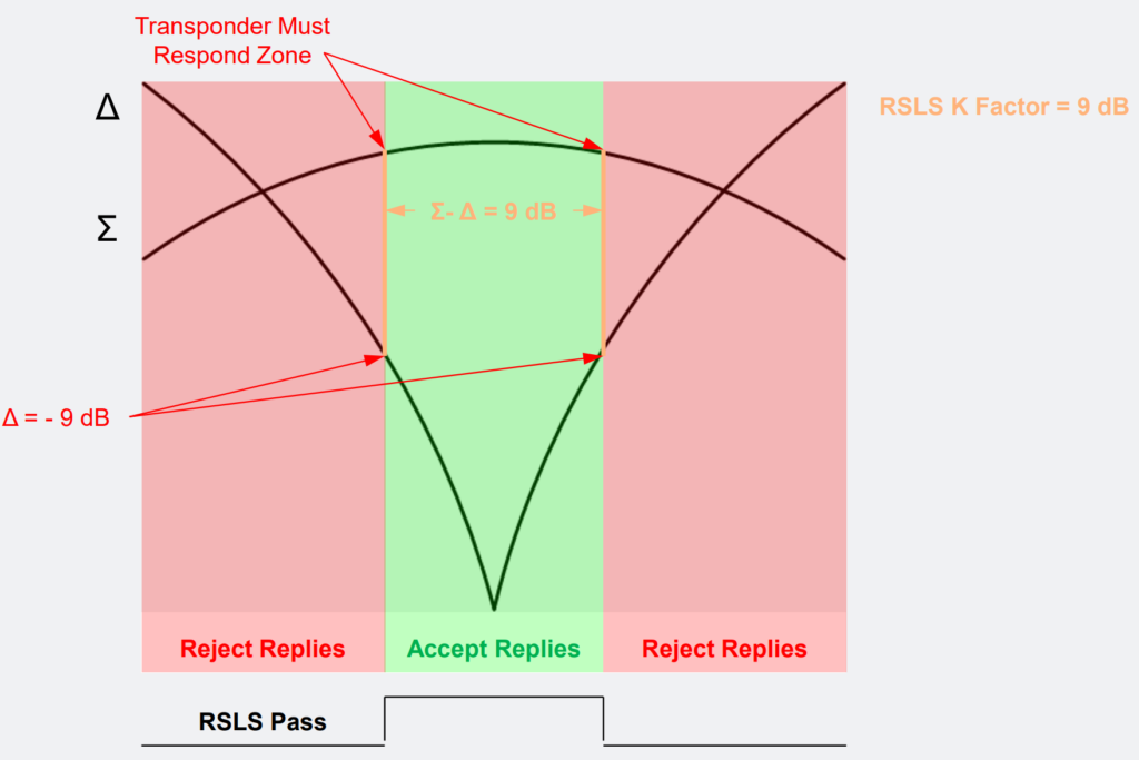
Receiver Side Lobe Suppression (RSLS).
Receiver Side Lobe Suppression (RSLS) is a technique employed to filter out unwanted responses or replies that originate from directions outside the main beam of the radar antenna. By implementing RSLS, radar systems can effectively ignore signals that come from sidelobes, focusing only on responses within the desired target area.
The RSLS K factor, expressed in decibels (dB), is a parameter used to specify the boundary of acceptable replies. It is calculated as the sum (Σ) minus the difference (Δ) between the main beam and sidelobes. As the K factor value increases, the acceptable region for replies narrows down, allowing for more precise targeting and discrimination of signals originating from the desired direction.
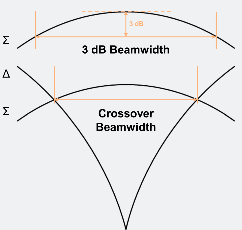
Interrogation Antenna Pattern Beamwidth.
RSLS Processing – Example (K = 9 dB).
Antenna Dwell Time.
Antenna dwell time refers to the duration for which a radar antenna remains focused or fixed on a particular area or target. It represents the period during which the radar beam is directed towards a specific location or object to gather information about it.
2-Channel vs 3-Channel Antenna System.
2-Channel Antenna.
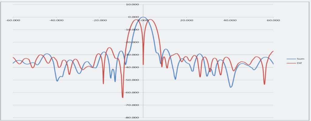
In radar systems, the terms “Sum (Σ)” and “Difference (Δ)” refer to specific signal processing techniques used during transmission and reception.
During transmission:
- “Sum (Σ)” involves combining multiple signals or components to generate a composite signal with enhanced characteristics.
- “Difference (Δ)” involves subtracting one signal from another to isolate specific features or eliminate unwanted elements.
In reception:
- Both “Sum (Σ)” and “Difference (Δ)” signals are received and processed to extract useful information about the target.
- The received signals undergo further processing to determine azimuth, or the horizontal angle of the target relative to the radar’s position.
Receiver Side Lobe Suppression (RSLS) is applied to both “Sum (Σ)” and “Difference (Δ)” signals to mitigate unwanted side lobes, which are weaker radar echoes that can interfere with accurate target detection.
For effective RSLS:
- The “Difference (Δ)” signal must provide coverage for Interference Side Lobe Suppression (ISLS), ensuring that high-power side lobes are present.
- However, reducing the power of the main lobe in the “Difference (Δ)” signal can lead to a wider effective beamwidth, resulting in decreased azimuth performance.

To enhance performance, boosting the power of the “Difference (Δ)” main lobe will make the radar beam narrower, which is beneficial. However, this action decreases the power of the “Difference (Δ)” side lobes. When the side lobe power is reduced, there’s a higher chance of encountering punch-through or false targets.
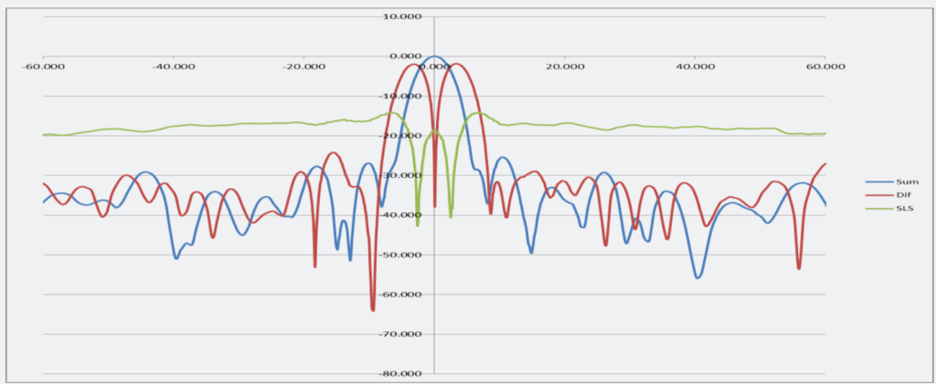
3-Channel Antenna.
The 3-channel antenna system operates as follows:
- Transmit: It uses two channels, denoted as “Σ” and “Ω”.
- Receive: It utilizes three channels, denoted as “Σ”, “Δ”, and “Ω”.
For azimuth determination, the system relies on signals from the “Σ” and “Δ” channels. Sidelobe suppression (RSLS) is applied to the signals received from both the “Σ” and “Δ” channels, as well as to the “Σ” and “Ω” channels. The system requires that signals pass both RSLS thresholds to be accepted.
The “Ω” channel is crucial for providing Interference Suppression Lobe Suppression (ISLS) coverage. To enhance azimuth performance, the main lobes of the “Δ” channel are heightened, resulting in a narrower effective beamwidth.
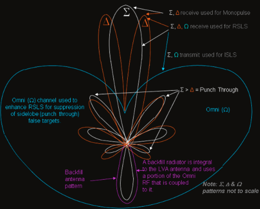
3-Channel LVA IFF Antenna with Backfill.
The 3-Channel LVA IFF Antenna with Backfill operates as follows:
- Transmit: The Interrogator sends out signals on the Sum and Omni channels to ensure Interference Suppression Lobe Suppression (ISLS).
- Receive: It picks up signals on the Sum, Difference, and Omni channels.
For azimuth determination, the system utilizes signals from the Sum and Difference channels through monopulse techniques.
In the system, the Difference and Omni channels’ radio frequency (RF) levels are compared to the Sum RF levels to implement Receiver Side Lobe Suppression (RSLS). This comparison helps in mitigating false transponder replies in the sidelobe regions of the antenna.
The inclusion of the Omni channel in the 3-channel antenna offers a larger suppression margin compared to a 2-channel antenna. This added margin helps protect against false transponder replies caused by sidelobe conditions. It significantly reduces the occurrence of false sidelobe target conditions, which can be problematic for ATC/IFF display operators and prevent unwanted transponder replies.
Azimuth Determination.
Beam split vs Monopulse.
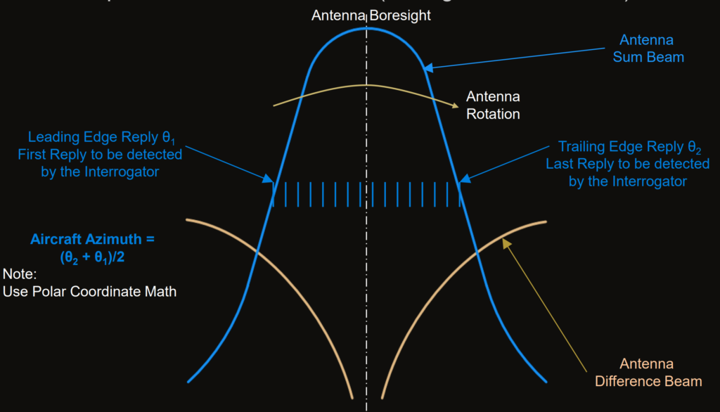
In the Beam split Azimuth Determination (Sliding Window Method):
- The target azimuth is determined by finding the center azimuth between the first reply and the last reply received during the scanning beam process.
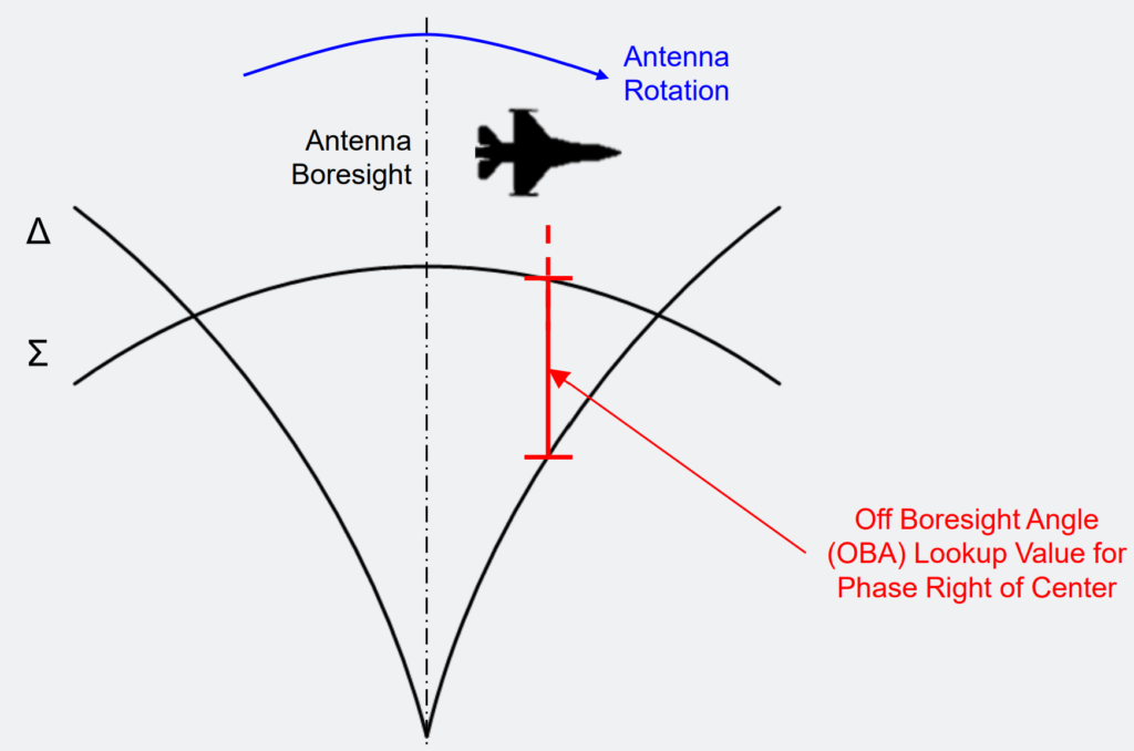
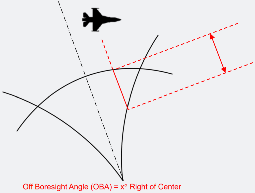
For Monopulse Azimuth Determination:
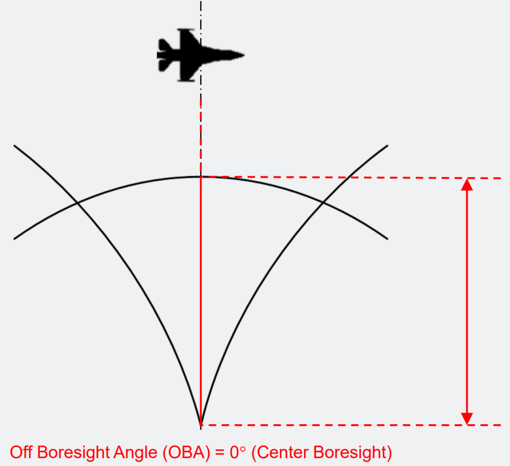
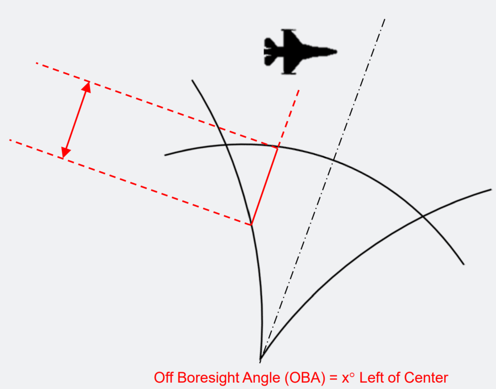
- The Interrogator relies on the relationship between the main beam Sum (Σ) and Difference (Δ) patterns, known as the Off-Boresight Angle (OBA) table.
- It calculates the target azimuth using the received Sum (Σ) and Difference (Δ) radio frequency (RF) levels and referencing them against the OBA lookup.
- Proper calibration of the input RF signals is necessary to ensure accurate measurement of the received replies’ antenna Off-Boresight Angle.
- Multiple samples of azimuth data are collected from a target during each scan, and these samples are averaged to obtain a more precise measurement.
If the monopulse data is considered unreliable by the processing algorithm, the system automatically switches back to the beamsplit method for azimuth determination.
Monopulse.
Monopulse, Right of Center.
Monopulse at Boresight.
Monopulse, Left of Center.
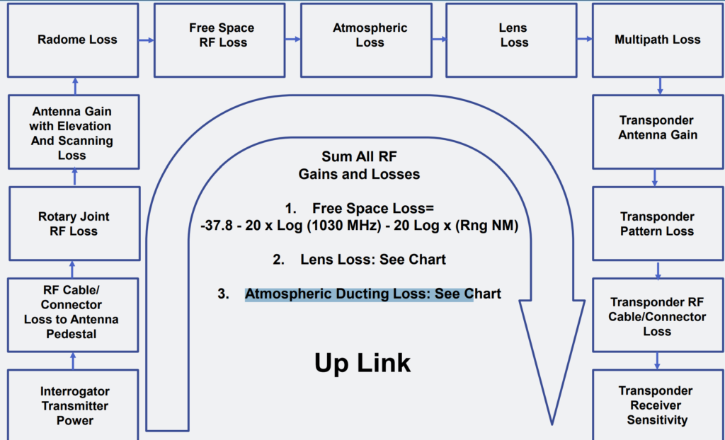
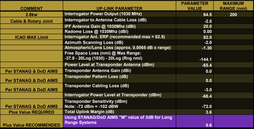
RF Uplink Budget – Interrogator to Transponder.
The RF uplink budget refers to the calculation of various factors affecting the transmission of radio frequency (RF) signals from the interrogator to the transponder in an IFF/SSR system. This budget accounts for different elements to ensure successful communication between the interrogator and the transponder.
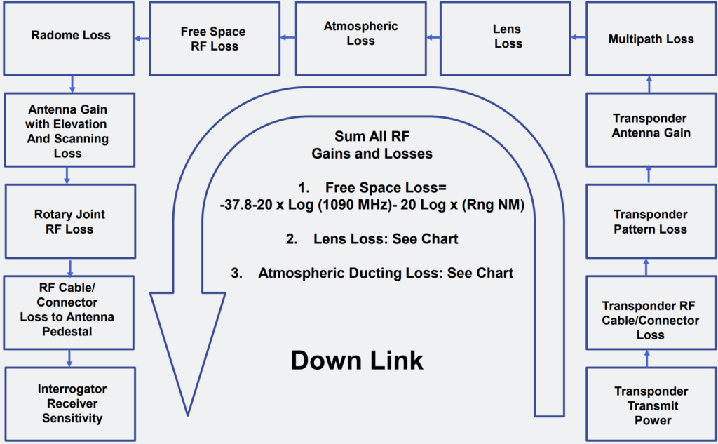
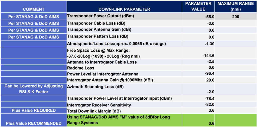
RF Downlink Budget – Transponder to Interrogator.
The RF downlink budget refers to the calculation of various factors affecting the transmission of radio frequency (RF) signals from the transponder to the interrogator in an IFF/SSR system. This budget accounts for different elements to ensure successful communication between the transponder and the interrogator.
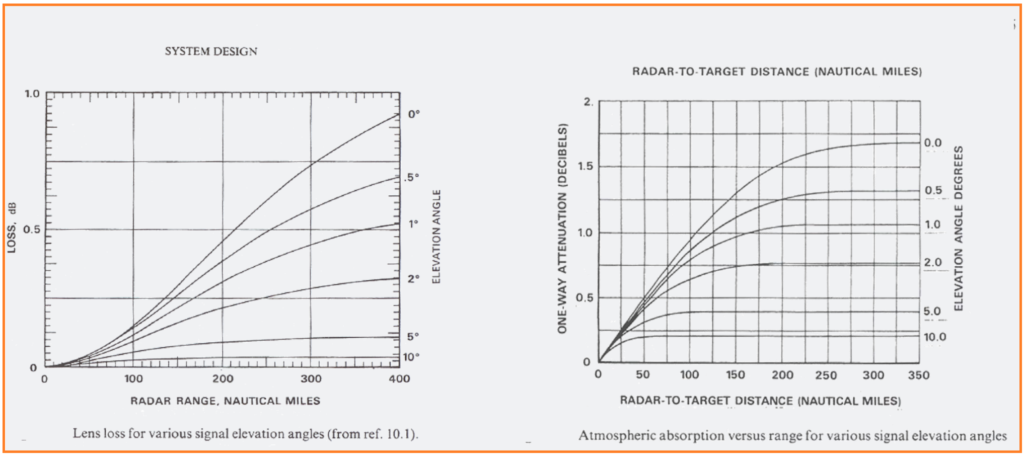
Lens Loss & Atmospheric Absorption Loss.
Lens loss and atmospheric absorption loss are two factors that contribute to the attenuation or reduction in the strength of radio frequency (RF) signals in an IFF/SSR system.
Up-Link Example.
An up-link example in the IFF/SSR system refers to the transmission of radio frequency (RF) signals from the ground-based interrogator to the transponder aboard an aircraft.
Down-Link Example.
A down-link example in the IFF/SSR system refers to the transmission of radio frequency (RF) signals from the aircraft’s transponder back to the ground-based interrogator.
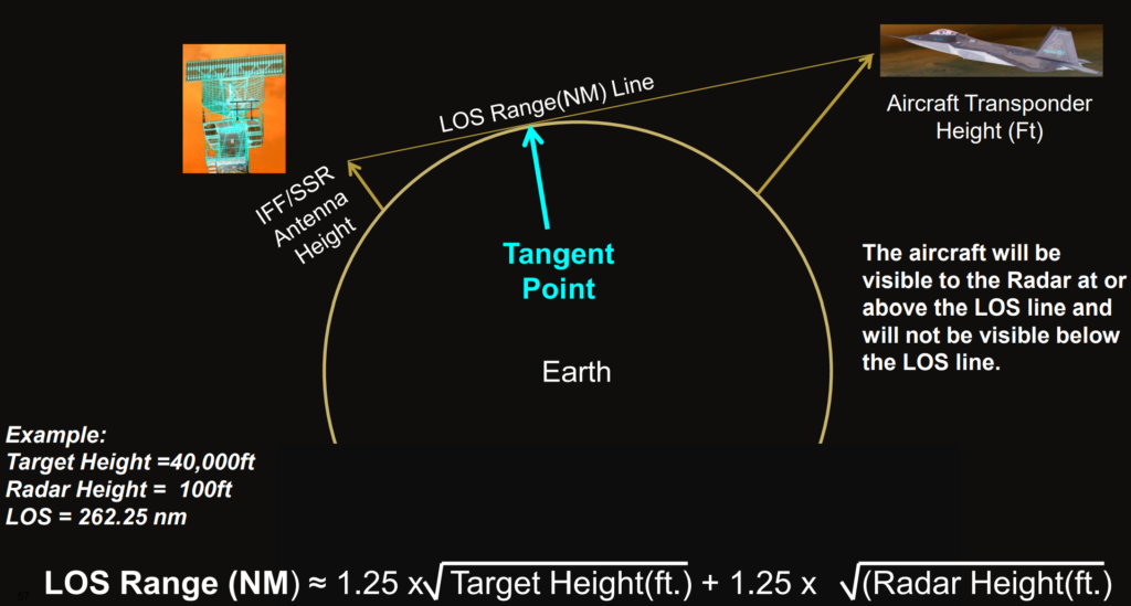
Line of Site (LOS) Coverage Due to Earth Curvature.
Line of sight (LOS) coverage due to Earth curvature refers to the limitations imposed on the direct visibility or communication between two points on the Earth’s surface as a result of the curvature of the Earth.
SSR/IFF Processing Challenges.
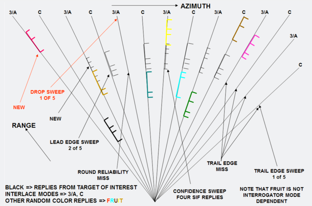
What is False Replies Unsynchronized in Time (FRUIT)?
FRUIT, which stands for False Replies Unsynchronized In Time, refers to replies received by an interrogator that were generated by a transponder in response to a different interrogator’s interrogation. Here’s a breakdown of FRUIT and how Telephonics Interrogators handle it:
FRUIT occurs when multiple interrogators use asynchronous interrogations, causing the received range of a reply to be out of sync with the intended interrogator’s timing.
Telephonics Interrogators Approach:
- Pseudo-random interrogation stagger: Telephonics Interrogators employ a staggered interrogation pattern to minimize FRUIT replies from correlating in range, thus reducing the likelihood of false targets.
- GTC (Garble Threshold Control): This feature helps eliminate low-level FRUIT replies, improving the accuracy of target detection.
- Range correlation window: A small window is used to correlate the range of received replies with the expected timing, distinguishing between real synchronous replies and FRUIT.
- Antenna beam leading edge detection: By using criteria such as antenna beam leading edge and reply count confidence, Telephonics Interrogators maximize the probability of detecting real targets while minimizing false reports from FRUIT.
Target Reporting Criteria: Targets must meet specific criteria, including leading edge detection and reply count confidence, to be reported accurately, ensuring that only genuine targets are identified and tracked.

SIF Reply Pulses.
SIF Reply Pulses, also known as Secondary Surveillance Radar (SSR) Interrogation Friend or SIF replies, are specific signals transmitted by aircraft transponders in response to interrogations from SSR systems.
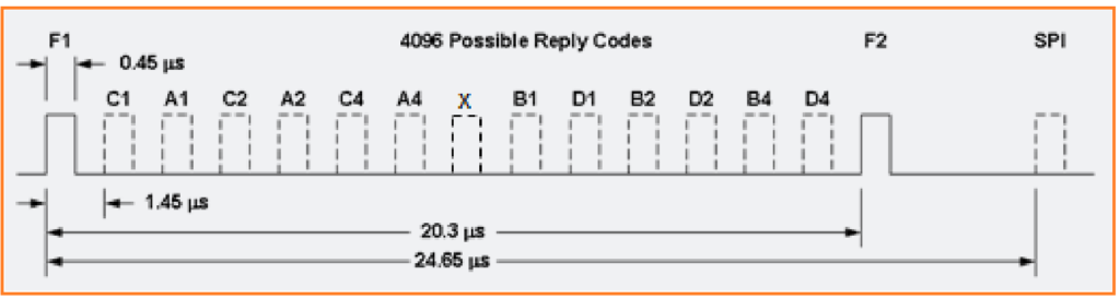
What is Garble Condition?
Garble conditions occur when two or more closely spaced replies overlap the specified pulse position boundary. Garble happens when the pulses of two or more replies overlap in time, making it difficult to distinguish individual code pulses clearly. This results in uncertainty about the correct code transmitted by each aircraft’s transponder.
Overlap Boundary: Garble occurs when the pulses overlap within a certain time window, typically defined as 1.45 ± 0.40 microseconds around the expected pulse position.
Interleaved Replies: In addition to overlapping replies, there can be interleaved replies, where closely spaced replies fall between pulse positions but do not overlap directly.
Effects: When garble occurs, the correct code cannot be determined with certainty. Both replies are marked as garbled, indicating that their codes are ambiguous. To resolve this, multiple ungarbled reply codes for the same mode may be required for valid code determination.
Resolution: Internal secondary surveillance radar (SSR) systems may employ techniques like SIF plot tracking to aid in correct code determination from scan to scan. The target report generated by the SSR system will indicate whether the SIF code is valid or garbled.
In summary, garble conditions pose challenges for accurately identifying aircraft using SSR systems, but techniques like code tracking and analysis help mitigate these issues to ensure reliable identification of aircraft in radar systems.
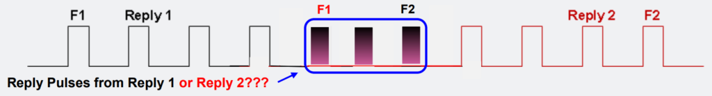
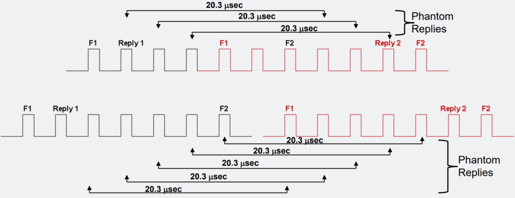
Phantom Conditions.
Phantoms are instances where pulses from two or more closely spaced replies align to create false F1/F2 brackets, which are spaced approximately 20.3 microseconds apart. Here’s a breakdown:
- Definition: Phantoms occur when the pulses from multiple closely spaced replies align in such a way that they create false F1/F2 brackets, which are key components of the SSR reply format.
- Phantom 2: This term refers to a specific type of phantom where garble is caused by more than two replies overlapping, further complicating the identification process.
- Rejection: It’s essential to reject all phantom conditions during the reply extraction process to ensure accurate and reliable identification. Phantoms introduce ambiguity and can lead to incorrect interpretation of the radar data.
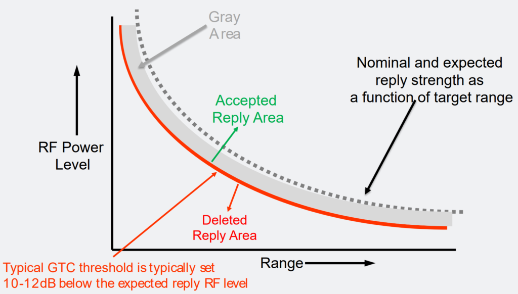
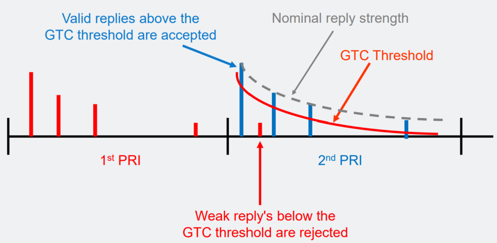
What is Gain Time Control (GTC)?
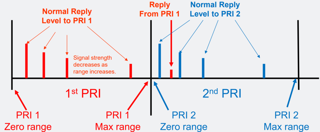
Replies from targets received after the interrogation period ends may resemble low-range replies during the next interrogation period, which is sometimes referred to as “Second-Time-Around” replies.
Here’s an explanation:
- Second-Time-Around Replies: When replies from targets arrive after the interrogation period ends, they can be mistakenly interpreted as low-range replies during the next interrogation cycle. This can occur when the replies are received just past the maximum range and are detected at the beginning of the subsequent interrogation period.
- Prevention Measures:
- GTC (Garble Threshold Control): Utilized to prevent “Second-Time-Around” replies from generating false targets. GTC helps in filtering out unreliable or inconsistent reply signals.
- Interrogation Timing Stagger: Another method to prevent the misinterpretation of “Second-Time-Around” replies. By staggering the timing of interrogations, the system can better distinguish between genuine and spurious replies.
Weak Replies Past Max Range.
In cases where a target replies beyond the maximum interrogation range of a PRI interval, its signal may appear as a low-range reply during the next PRI interrogation. However, the received signal’s low RF power level does not align with the expected power level for that range. GTC is employed to discard such unreliable signals and ensure accurate target detection and tracking.
GTC Curve.
What is Multipath Basics?
Multipath interference is a significant challenge in SSR (Secondary Surveillance Radar) systems, often leading to performance degradation.
Multipath interference occurs when a transmitted signal, originating from a single source, reaches the receiver via both a direct path and one or more reflected paths. These reflections can result from interactions with various objects or surfaces in the environment.
The interference can either reinforce (constructive) or attenuate (destructive) the received signal. This outcome depends on factors such as the relative phase and power levels of the direct and reflected signals.
Signal Combination: When RF (Radio Frequency) energy arrives at an antenna through different paths, the signals combine. If the signals arrive in phase, they add up, leading to constructive interference. Conversely, if they arrive out of phase, they can cancel each other out, causing destructive interference.
Factors Affecting Interference: The degree of interference is influenced by several factors:
Path Delay: The time difference between the direct and reflected signals reaching the receiver affects interference. Longer delays can lead to more pronounced interference effects.
Relative Phase: The alignment of the phase of the direct and reflected signals determines whether constructive or destructive interference occurs.
Power Levels: Disparities in the power levels of the direct and reflected signals also impact interference. Higher power reflections may dominate over weaker direct signals, affecting the overall received signal quality.
Managing multipath interference is crucial for maintaining the accuracy and reliability of SSR systems, requiring techniques such as signal processing algorithms, antenna design optimization, and site selection strategies to mitigate its effects.
Horizontal/Vertical, Uplink/Downlink Multi-path.
Multipath interference can manifest differently depending on the orientation of the reflecting surfaces and the radar system’s configuration:
- Horizontal Plane Multipath: Occurs when reflections occur in the horizontal plane, leading to azimuthal reflections. This phenomenon typically arises from structures acting as radar reflectors, such as buildings or terrain features. Horizontal plane multipath can generate false reports by reflecting signals in directions different from the actual targets.
- Vertical Plane Multipath: Involves reflections in the vertical plane, resulting in radial reflections. The earth’s surface often acts as a reflector in vertical plane multipath scenarios. These reflections can cause false reports and signal fading, impacting the accuracy of radar measurements.
- Uplink Vertical Plane Multipath: Refers to reflections that affect the transmission of interrogation pulses from the radar to the transponders. These reflections may lead to misinterpretations by the transponders, causing them to reply in the wrong mode or at incorrect ranges. Mode conversion, where transponders switch modes unintentionally, can also occur due to uplink vertical plane multipath.
- Downlink Multipath: Occurs when reflections affect the signals transmitted from transponders to the interrogator. This can result in the generation of false or extra replies, which may be slightly delayed compared to the genuine replies. Downlink multipath can cause garbling of transponder codes, pulse cancelations, or additions, leading to inaccuracies in the received data.
Vertical Multi-Path.
Radar multipath, also known as radar echo, is a physical phenomenon influenced by various factors:
- Height of the Radar Antenna and Target Aircraft: The elevation of both the radar antenna and the target aircraft above the earth’s surface affects the likelihood of multipath reflections.
- Range between Target and Radar: The distance between the radar and the target aircraft impacts the timing and strength of reflected signals.
- Vertical Multipath: In cases of vertical multipath, the earth serves as a reflector, creating a secondary path for radar signals to reach the receiving antenna.
- Timing Discrepancies: Since direct and reflected signals travel different distances, they reach the receiving antenna at different times, causing timing discrepancies.
- Deterministic Nature: Multipath interference can be calculated theoretically based on radar and target geometry. However, actual measurements may deviate slightly due to atmospheric conditions, altitude measurement inaccuracies, and other factors.
- Multipath Delay Calculation: SSR radar signals travel at a known speed (approximately 12.359 microseconds per nautical mile). Multipath delay can be calculated based on the difference in path lengths.
- Types of Multipath: Multipath can occur on both the interrogation signal (uplink multipath) and the transponder reply signal (downlink multipath). Combinations of uplink and downlink multipath can produce multiple reports from a single target in one beam dwell.
- Mode Conversion: Uplink multipath can lead to mode conversion, where the transponder decodes an incorrect pulse spacing and replies to the wrong mode. This can result in replies generated at incorrect ranges.
- Range Offset: The range offset of an uplink multipath reply is determined by target and platform geometry, as well as the modes of interrogation.
Overall, multipath interference poses challenges to radar systems by potentially generating false or misleading reports, especially when uplink and downlink multipath conditions coincide.
Ground Interrogator – Vertical Multi-Path Geometry.

Note: Ground reflections also produce Up-link Multi-Path interference on the interrogation signals.
Lobbing due to Vertical Multi-Path.

Lobbing as seen on Radar Display.
Lobbing, as observed on a radar display, refers to the phenomenon where an aircraft appears to fluctuate in altitude or exhibit abnormal movements due to ground reflections. This effect is typically visible on radar displays as an aircraft flying through antenna minima.

Horizontal Multi-Path Reflections.

What is Antenna Pattern Distortion?
Antenna pattern distortion occurs when the expected radiation pattern of an antenna is altered due to various factors such as installation location, platform structures, and environmental conditions. This distortion can lead to performance degradation in secondary surveillance radar (SSR) systems, resulting in issues such as inaccurate azimuth readings, incorrect code identification, false target detections, and reduced target detection capabilities.
Several factors contribute to antenna pattern distortion in SSR systems:
- Platform Structures: Antennas installed on ground sites, ships, or airborne platforms can experience distortion due to the presence of platform structures. These structures, such as aircraft wings, tails, wheels, struts, and appendages, can interfere with the propagation of RF energy and alter the intended antenna pattern.
- Installation Location: Ground systems may experience distortion based on the height of the antenna above the ground and nearby structures. The proximity of buildings, terrain features, or other obstacles can impact the antenna’s radiation pattern.
- Aircraft Skin Effects: The composition and conductivity of the aircraft’s skin can affect the transmission and reception of RF signals, leading to changes in the antenna pattern.
- Environmental Factors: Environmental conditions such as weather, atmospheric interference, and electromagnetic interference can also contribute to antenna pattern distortion.
To mitigate antenna pattern distortion and ensure optimal system performance, SSR/IFF designs must account for installed system performance as a key requirement. This may involve careful antenna placement, structural modifications to minimize interference, and ongoing maintenance to address any issues that arise. Additionally, rigorous testing and calibration procedures can help identify and correct antenna pattern anomalies before they impact system operation.

New Initiatives in SSR and IFF.
New initiatives in secondary surveillance radar (SSR) and identification friend or foe (IFF) systems are aimed at addressing evolving requirements and challenges in airspace management and security. Some of these initiatives include:
- Miniaturization and Efficiency: New IFF systems are being developed to be lighter, smaller, and more power-efficient to meet the demands of modern platforms. This is particularly important for unmanned aerial vehicles (UAVs), which require compact and energy-efficient transponders to operate effectively in shared airspace with other aircraft.
- Integration with UAVs: With the increasing use of UAVs in civilian and military applications, IFF/ATC transponders are being adapted to enable UAVs to comply with airspace regulations and safely integrate with manned aircraft traffic.
- Transponder Squitter Capability: Transponder squitter capability, integrated into technologies such as Automatic Dependent Surveillance-Broadcast (ADS-B), Universal Access Transceiver (UAT), and Mode 5 Level 2, provides accurate GPS position information for air targets. This aids air traffic control (ATC) and IFF operations by enhancing situational awareness and facilitating more efficient airspace management.
- Passive Squitter Detection Systems: Passive squitter detection systems are being developed to enhance situational awareness for ATC and IFF operators. These systems detect and analyze squitter signals emitted by aircraft transponders, providing valuable information about aircraft positions and movements.
- GPS Denial and Jamming Protection: With the increasing threat of GPS signal denial and jamming, new SSR and IFF systems are incorporating features to protect against such attacks. This includes implementing measures for GPS denial and jamming detection, as well as reporting mechanisms to alert operators of potential disruptions to GPS signals.
