1
SCOPE ……………………………………………………….
2 REFERENCES ……………………………………………………….3 DEFINITIONS ……………………………………………………….4 GENERAL ……………………………………………………….5
SELECTION PHILOSOPHY …………………………..
6 DESIGN LIMITATIONS……………………………………………………….6.1 Materials ……………………………………………………….6.2 Sizes ……………………………………………………………………………………6.3 Wall Thickness ……………………………………………………….6.4 Ends ……………………………………………………………………………………6.5 Lengths ……………………………………………………….6.6 Galvanizing ……………………………………………………….6.7 Pipe Joints ……………………………………………………….6.8 Joint Efficiency ……………………………………………………….6.9 Wall Thickness ……………………………………………………….6.10 Special Requirements ……………………………………………………….6.11 Marking ……………………………………………………….6.12 Mill Test and Chemical Analysis Report …………………………..6.13 Nipples ……………………………………………………….6.14 Piping Material Classes ……………………………………………………….7
SPECIFIC SERVICE LIMITATIONS …………………………..
7.1 Selection ……………………………………………………….7.2 Carbon Steels ……………………………………………………….7.3 Chrome alloys ……………………………………………………….7.4 Stainless Steel ……………………………………………………….7.5 Other Materials ……………………………………………………….7.6 Pipe For Pipelines ……………………………………………………….7.7 Metallurgist ……………………………………………………….8 MATERIAL STANDARDS ……………………………………………………….8.1 Process ……………………………………………………….8.2 Ordering Information ……………………………………………………….8.3 Heat treatment ……………………………………………………….8.4 Chemical Composition ……………………………………………………….8.5 Heat Analysis ……………………………………………………….8.6 Product Analysis ……………………………………………………….8.7 Tensile Requirements ……………………………………………………….8.8 Bending Requirements ……………………………………………………….8.9 Flattening Tests ……………………………………………………….8.10 Hydrostatic Test ……………………………………………………….8.11 Other Testing ……………………………………………………….8.12 Other Requirements ……………………………………………………….8.13 Lengths ……………………………………………………….8.14 Supplementary Requirements …………………………..8.15 Reports ……………………………………………………….9
APPLICATION ……………………………………………………….
10 SAMPLE PURCHASE DESCRIPTION…………………………..
1 Scope
1.1 This standard covers the design and material options and limitations on the selection of
pipe for use in SABIC piping Line Classes, SES P02-S01, P02-S14, and P03-S01. This
standard prescribes materials and application of the listed materials and allowable listed in
ASME B31 codes appropriate to specific piping systems.
1.2 This standard covers the minimum mandatory requirements for pipe in new piping
systems. Pipe for maintaining or tie-in to existing systems may be in accordance with
original specifications.
1.3 Tubing, defined by actual OD in mm, is not included in this standard.
1.4 In case of conflict between the requirements specified herein and those stipulated
elsewhere in other SES and international codes & standards; the most stringent
requirements shall be applicable.
2 References
SABIC Engineering Standards (SES)
P02 S01 Piping Materials Standard Specifications for Carbon Steel-Part I,Group 1
P02 S14 Piping Materials Standard Specification for Low Alloy Steel- Part I,Group 2
P03 S01 Piping Materials Standard Specifications for Stainless Steel- Part II
P04 S01 Piping Materials Standard Specifications Part III (Metallic and Non-metallic piping
and components for utility services) P12 S04 Color coding Criterion
American Petroleum Institute (API)
5L Line Pipe
941 Steel for Hydrogen service at elevated temperatures and pressures in petroleum and
petrochemical plants
American Society for Testing and Materials (ASTM)
A 53 Specification for Pipe, Steel, Black and Hot-Dipped, Zinc Coated, Welded and Seamless
A 153 Specification for Zinc coating (Hot-dip) on Iron and Steel Hardware
A 106 Specification for Seamless Carbon Steel Pipe for High-Temperature service
A 312 Specification for Seamless and Welded Austenitic Stainless Steel Pipes
A 333 Specification for Seamless and Welded Steel Pipe for Low-Temperature Service
A 335 Specification for Seamless Ferritic Alloy- Steel Pipe for High-Temperature Service
A 530 Specification for General Requirements for Specialized Carbon and Alloy Steel Pipe
A 671 Specification for Electric-Fusion-Welded Steel Pipe for Atmospheric and Lower
Temperatures
A 672 Specification for Electric-Fusion-Welded Steel Pipe for High-Pressure Service at
Moderate Temperatures
A 691 Specification for Carbon and Alloy Steel Pipe, Electric Fusion -Welded for High-
Pressure at High Temperatures
B 161 Specification for Nickel Seamless Pipe and Tube
B 165 Specification for Nickel-Copper Alloy (UNS N04400) Seamless Pipe and Tube
B 167 Specification for Nickel-Chromium-Iron Alloy (UNS N06600,
N06601,N06603,N06690,N06693,N06025,N06045 and N06696) and Nickel chromiumcobalt-molybdenum
alloy(UNS N06617) Seamless pipe and Tube
B407 Specification for Nickel-Iron-Chromium Alloy Seamless Pipe and Tube
B464 Specification for Welded
UNS N08020,N08024
and N08026
alloy pipe
-B 622 Specification
for Seamless Nickel and
Cobalt Alloy Pipe and
Tube
American Society of Mechanical Engineers (ASME)
B16.25 Buttwelding Ends
B31.1 Power Piping
B31.3 Process Piping
B31.4 Pipe Line Transportation system for liquid hydro carbons and other liquids
B31.8 Gas Transmission and Distribution Piping Systems
B36.10 Welded and Seamless Wrought Steel Pipe
B36.19 Stainless Steel Pipe
Manufacturers Standardization Society
SP-6 Standard Finishes for contact faces of pipe flanges and connecting-end flanges of
valves and fittings
SP-25 Standard Marking System for Valves, Fittings, Flanges, and Unions
National Association of Corrosion Engineers (NACE)
MR0175/ ISO 15156 Petroleum and natural gas Industries-Materials for use in H2S
Containing environments in oil and production-Part 1, Part 2 & Part 3
Process Industry Practices (PIP)
Selection of Piping Line Class Content
PNE00001 Design of ASME B31.3 Metallic Piping Systems (PIP)
3
Definitions
For the purpose of understanding this standard the following definitions apply.
Austenitic. Stainless steels with austenite microstructure
Cold Services. Services between -45°C and -73°C are classified as cold services.
Cryogenic Services. Services below -73°C are classified as cryogenic services.
DSAW. Double Submerged Arc Welded
EFW. Electric Fusion Welded
ERW. Electric Resistance Welded
Ferritic. Stainless steels with ferrite
General Service. General service denotes fluids with no special requirements.
Hydrocarbon Services. Process streams of liquid or gaseous hydrocarbons, including two
and three phase hydrocarbon materials.
Hydrogen Services. Process streams containing relatively pure hydrogen, and component
streams containing hydrogen with a partial pressure of 3.5 Bar(A) & higher.
JE. Joint Efficiency
Low Temperature Services. Services between -18°C and -45°C are classified as low
temperature services.
NDT. Non Destructive testing
Nipple. A piece of pipe less than 300 mm long that may be plain, threaded on both ends or
one end
SAW. Submerged Arc Welded
Service. Service is related to pressure, temperature, flange rating, special components, and
special requirements of the fluid in a piping system.
SMYS. Specified Minimum Yield Strength
4 General
4.1 This standard explains the design, material requirement and limitations on the
selection of various piping materials to be used in SABIC. These are identified in four distinct
areas:
a. Approach
b. Design limitations
c. Specific service limitations
d. Material Standards
e. Material limitations
5
Selection Philosophy
Selection of pipe falls into two schools of thought.
5.1 Pipeline Approach: When pipelines, and production facilities are being built the
emphasis is placed on pipe wall. Generally there is a great amount of pipe, and quantities of
fittings and valves are small by comparison. Minimizing of pipe wall is the major economic
factor. The extra cost of custom made fittings is far outweighed by the savings on the pipe.
Pipe is purchased by weight, so the added cost of high strength material to lower the pipe
wall is a reasonable consideration. When high strength material is specified, extra inspection
and more stringent interpretation are also necessary. The cost of the extra inspection is also
a reasonable consideration. Spare parts warehousing is a small consideration.
5.2 Plant Approach: When plants are built, the emphasis is on standardized materials. The
design is such that materials made to the specified standard are adequate for the service.
Certain specific services may require additional inspection, or special requirements, but these
are for service, and not economics. Materials are usually purchased from warehousing
companies. The relative cost of pipe is a considerably smaller percentage of the total cost,
compared with pipelines. The cost of machinery, and equipment take a large part of the
project budget. The cost of fittings and particularly valves makes up a large part of the whole
piping budget.. Pipe walls may be bumped up, if the quantity is small, to a greater thickness
that is more available, or already specified in large quantities. There is a price vs. availability
relationship that is easy to overlook.
5.3 Price vs. Availability: The price vs. availability relation can be shown by the following
examples. Type 304 stainless steel costs less than type 316. Many valve manufacturers
standardize on type 316, because it is generally suitable for type 304, and 316 services. If
type 304 is the only choice, a valve will have a higher price, and extended delivery. Even if
the price is the same, the lack of availability can slow a project.
6 Design Limitations
6.1 Materials
6.1.1 Pipe made by acid-Bessemer process shall not be acceptable, steel pipe
shall be made by open hearth, electric furnace or basic oxygen process.
6.2 Sizes
a. The pipe dimension shall be in accordance with ASME B36.10 for wrought steel
(C.S/A.S), to ASME B36.19 for stainless steel pipe and respective ASTM standard for
non ferrous & non-metallic pipes. Intermediate sizes and the sizes NPS
1/8, 1/4, 3/8, 1-1/4, 2-1/2, 3-1/2, 5 and 22” shall not be used except when necessary to match
equipment connections. In this case a suitable transition shall be made as close as
practical to the equipment.
b. The minimum allowable pipe size, including vents and drains, is NPS
3/4.
6.3 Wall Thickness
6.3.1 Standard for Wall Thickness: Wall thickness may be expressed as WT, STD,
XS, and XXS, Schedule, and plate thickness. Weight classes and schedules are
defined in ASME B36.10 & B36.19
6.3.2 Pipe Made From Plate: Pipe made from plate shall have the wall thickness
expressed in mm.
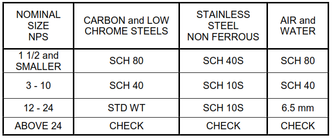
6.3.3 Minimum Wall Thickness: The minimum wall thickness for pipe is generally
the minimum thickness that will stand under its own weight, with minimum deflection
is as follows.
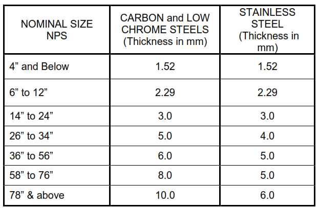
Wall thickness is always calculated for the design temperature and pressure, in
accordance with the appropriate ASME B31 code. The thickness is rounded up to the
next commercially available thickness, or to the minimum thickness as follows.
6.3.4 Wall Thickness Standardization: Wall thickness standardization is necessary
to minimize stocking requirements, and take advantage of quantity pricing.
a. The wall thicknesses for schedules and weights are concurrent in some
sizes. Sch 40 and std wt are the same wall up to NPS 10, and sch 80 and XS
have the same wall through NPS 8. It is confusing to have, for instance, an
NPS 2 sch 40, and a NPS 2 standard weight length of pipe, because they are
identical. PIP PNE00001, and accompanying line classes use weights in the
material classes. To avoid duplication of effort, sch 40 shall not be used NPS
10 and smaller, and sch 80 shall not be used NPS 8 and smaller.
b. Following the logic of the plant approach materials, are purchased from
suppliers, on an expedient bases. Suppliers stock, and buy mill runs based
on standardized walls. Generally suppliers will have sch 40, sch 80, and sch
160 in stock, or on order. Odd pipe walls such as sch 60, sch 100, sch 120,
and sch 140 are not available, without waiting for a special mill run. Pipe is
sold by weight, so the pricing data is also based on weight, without regard to
availability. When the purchase is made, the pipe will be what is available at
that time. Generally, the quantities of odd pipe walls are small, and it is
expedient to “bump” the wall to the higher number. A spread sheet listing
size against class, with the wall in the cell, will show relative amount of pipe
each wall.
c. In the plant approach, pipe is not specified in a vacuum. Pipe is welded
to flanges and fittings in relatively large quantities. The major criterion in pipe
wall selection may not be from temperature and pressure, but from
availability of fittings and flanges. Piping is a system, and other items must
be considered during selection. When pipe is made from plate, the
accompanying fittings may be special order, and affect the critical path.
6.4 Ends
6.4.1 Threaded End Pipe: Threaded pipe shall be provided threaded and coupled.
All pipe threads shall confirm to ASME B 1.20.1 unless otherwise specified.
6.4.2 Pipe For Socket weld Systems: Pipe intended for socket-welding shall be
square cut.
6.4.3 Buttwelding Ends: Butt welding ends shall be in accordance with the
requirements of ASME B16.25.
6.5 Lengths
Pipe shall be supplied in double random lengths.
6.6 Galvanizing
Galvanizing shall be applied in accordance with ASTM A153.
6.7 Pipe Joints
6.7.1 Seamless
a. Wrought Pipe: Seamless pipe is made by extrusion, or by piercing and
rolling.
b. Casting: Cast pipe suitable to be qualified as seamless must be
centrifugally cast.
c. Forging: Seamless pipe can be made by the forging and boring process.
6.7.2 ERW: ERW pipe is Electric Resistance Welded. In this process, flat plate is
formed into a cylinder, and put through energized rollers that press the seam together
and provide a resistance weld. ERW pipe has reduced allowable than seamless.
6.7.3 EFW
a. Electric Fusion Welded Pipe: EFW pipe is rolled into a cylinder and
welded with filler material. This is a fusion weld and may be qualified to
several levels.
b. DSAW: Submerged Arc Welding is a common form of EFW.
Depending on thickness, the manufacturing standard calls for a single, or
double weld. The thinner walls are welded outside, and thicker walls are
welded inside and outside, hence Double Submerged Welding, or DSAW.
6.7.4 Straight Seam: Straight seam refers a straight seam parallel to the
longitudinal axis. The hoop stress has no component in the axial direction. Straight
seam is made by drawing a plate through a series of rollers to make it a cylinder, for
welding.
6.7.5 Spiral Seam: Spiral welded pipe is made in a special machine that takes
coiled steel and rolls it into a spiral, which is welded into a pipe. This is a relatively
continuous process. The machine makes it relatively easy to change pipe size. The
convertability of the machine and limited stock required make this machine ideal for
local production. Spiral welded pipe is not readily accepted in the industry for other
than water, despite the favorable cost, and recent tightening-up of the standard.
6.8 Joint Efficiency
6.8.1 All pipe that is not seamless is subject to a joint efficiency. The committees
that publish the codes place restriction on the allowable stress for welded pipe. This
restriction is in the form of a joint efficiency, clearly stated in the codes.
6.8.2 Pipe can be qualified to a higher joint efficiency by inspection. The major
factor is radiography. The type and extent of radiography are listed in the codes.
6.9 Wall Thickness
The wall thickness is calculated in accordance with the applicable code, with all
tolerances added.
6.10 Special Requirements
There may be special requirements (such as NACE, H2 Service, O2 Service,
Cryogenic service etc) for the base material, the fabrication, or inspection. These
special requirements shall be clearly indicated in the Purchase Description.
6.11 Marking
Marking shall be in accordance with ASTM A530/A530M.
6.11.1 Color coding criterion for piping shall be in accordance with SES P12-S04.
6.11.2 Cast and malleable iron pipe and fittings shall be marked with cast-in-mold
lettering. Other pipe with low yield stress shall be marked within 300 mm of the bevel
or end, using low stress, interrupted dot die stamping. Other fittings with low yield
stress shall be similarly marked in the area designated by MSS SP-25.
6.11.3 Pipe and fittings meeting any of the conditions listed below, shall be marked
using a vibratory etch or other etching technique which does not induce a stress
concentration. Chemical etching is not permitted. For these materials, each vendor
shall supply information concerning their proposed marking techniques, the
application location, and the depth of marking with their quotation for SABIC
approval.
a. All 13 chrome and higher alloys.
b. Minimum yield strength of 414 MPa or greater.
c. A yield stress which is controlled by another specification.
6.12 Mill Test and Chemical Analysis Report
a. A certified mill test and chemical analysis report shall be submitted by the Seller
of all alloy pipe (including ASTM A333), and all pressure-containing alloy piping
components made from pipe not clearly marked in accordance with MSS SP-25.
b. A certified mill test and chemical analysis report is also required for carbon steel
pipe, nipples made from pipe, swages, and all pressure-containing carbon steel
components made from pipe not clearly marked in accordance with MSS SP-25, for
use in ASME Section I or ASME B31.1 piping systems.
c. When alloy material and carbon steel, as noted above, are purchased by an
outside shop pipe spool fabricator, the fabricator shall obtain these reports.
6.13 Nipples
Nipples with schedule 160 shall be installed in sizes NPS 2, and smaller pipe sizes in
vibration service where bracing can not be effectively provided.
6.14 Piping Material Classes
The piping material classes in these standards show the actual selections for piping,
as well as all piping materials, by example. The classes show pipe and all of the
associated materials for each service. These classes are to be used as a basis for
new services.
7
Specific Service Limitations
The materials for piping and pipelines
7.1 Selection
The actual material is specified by the company, or project metallurgist, or is part of
the Process Package.
7.2 Carbon Steels
Carbon steels are used in a variety of cases.
7.2.1 Low Strength: Low strength steels are generally only used for non-pressure
containing piping, such as gravity sewers
7.2.2 Regular: Regular steels are used for general service, including water, and
hydrocarbons. These are services with no special requirements.
7.2.3 Low Temperature: Low temperature carbon steel is steel that has been killed
to improve the microstructure to raise the fracture toughness, to reduce susceptibility
to brittle fracture. Low temperature carbon steel must be qualified by impact testing.
7.2.4 Killed Steel: Killed steel has the same improved microstructure as low
temperature carbon steel, but the improved microstructure reduces susceptibility to
sulfide cracking, as well as other related cracking. The fine grain structure, and
quality of structure also provide resistance to hydrogen attack.
7.2.5 NACE: When pipe is to be used in wet H2S, NACE MR0175/ ISO 15156 is
invoked to assure resistance to sulfide cracking, including the use of killed steel.
7.2.6 High Strength: High strength steels are generally not approved for use under
ASME B31.1 and B31.3. only the lowest of the grades are listed. High strength steels
are used in pipeline service to reduce the pipe wall.
7.3 Chrome alloys
7.3.1 Corrosion Resistance: Chromium alloy steel also use molybdenum to control
the microstructure. Corrosion resistance is improved.
7.3.2 Hydrogen Resistance: Generally, chrome and Molybdenum are added for
hydrogen resistance. The Nelson Curves show the relationship between the partial
pressure of hydrogen, temperature, and chrome content. The curves are found in API
941.
7.3.3 High Strength: The addition of chrome also improves high temperature
strength.
7.3.4 High Temperature: Graphitization takes place in carbon steel at temperatures
over 425 deg C, and hence chrome steel is recommended. Avoid specifying carbon
steel for steam piping close to limiting design temperature of 425 deg C.
7.4 Stainless Steel
7.4.1 Stainless Steel Types: Stainless steel offers resistance to corrosion in three
ways. Higher percentages of Chromium offer corrosion resistance, as an alloy.
Higher percentages of chrome with nickel alter the microstructure from ferrite to
austenite. The austenite offers the corrosion protection. Certain compositions will
produce what is known as duplex steel, which exhibits the qualities of ferritic and
austenitic steels.
7.4.2 300 Series: The 300 series steels are the most common. There are two basic
subtypes, in which the austenite is stabilized, or not. The most common types are
type 304 and type 316. These materials exhibit microstructure problems at various
temperatures. The austenite can be stabilized with Titanium, and Columbium
(Niobium). These grades are type 321 and 347. A metallurgist is required to make the
determination. 300 series stainless steels are extremely susceptible to chloride stress
cracking.
7.4.3 Duplex Steels: Duplex steels have the corrosion resistance of 300 series, the
abrasion resistance of 400 series, and are not subject to chloride cracking.
7.5 Other Materials
Some of the materials below are represented by the proprietary name for clarity.
7.5.1 Monel: Monel is a copper nicklel alloy, that is usually used around caustic, at
higher temperatures. Monel is not readily available, particularly valves.
7.5.2 Alloy 20: Alloy 20 is a proprietary name, but most alloys have similar names.
Alloy 20 is most used in acid services.
7.5.3 Nickel Alloys: Nickel alloys such as Incoloy and Inconel are proprietary, and
are used for high temperature services.
7.6 Pipe For Pipelines
With the pipeline approach, the material is usually high strength. The specific
composition of the metal depends on the makeup of the fluid carried. The limitations
on composition varies, so there is a separate specification specifically for line pipe.
Schedule 40 is usually considered the minimum pipe wall, for mechanical strength, in
small sizes, NPS 10 and smaller. When the pipe wall calculates at or below sch 40,
regular strength material is a considerable cost savings.
7.7 Metallurgist
All materials shall be specified by a qualified metallurgist.
8 Material Standards
The material standard specified dictates the requirements for the material.
8.1 Process
This is the process for production of the steel.
8.2 Ordering Information
Ordering information will tell the user what information to include.
8.3
Heat treatment
Heat treatment refers to various grades of material. This may also refer to a
supplemental requirement available.
8.4 Chemical Composition
Chemical composition refers to the makeup of the raw material. Under API 5L/ASTM,
there are equations, that allow variations in specific elements.
8.5 Heat Analysis
Heat analysis is the composition and physicals of the base material.
8.6 Product Analysis
Product analysis is chemical, and physical analysis of the product. This may vary
considerably, because elements burn out during the manufacturing process.
8.7 Tensile Requirements
Tensile requirements referring to tensile loads, and will include ultimate and yield
strengths.
8.8 Bending Requirements
Bending tests show flaws in welds.
8.9 Flattening Tests
The flattening test shows the integrity of pipe that has been flattened.
8.10 Hydrostatic Test
All pipe will get a hydrostatic test of some kind.
8.11 Other Testing
Other testing may be eddy current, but more commonly, ultrasonic testing. Welded
pipe may need hardness tests the quality of the weld, and subsequent heat
treatment.
8.12 Other Requirements
Other requirements depend on the wishes of the buyer.
8.13 Lengths
Lengths are the actual definition of random lengths for that specific standard.
8.14 Supplementary Requirements
Supplementary requirements are additional testing to qualify pipe for specific service.
These tests may be impact tests, radiography, ultrasonic tests and microstructure
tests,
8.15 Reports
Reports may be required for most of the above, under special conditions. There is a
cost associated with reports.
9 Application
The following are a few general applications and limitations.
9.1 Flammable liquids: Only steel pipe specifications shall be used to handle flammable
fluids.
9.2 E.R.W pipes shall be used only for Category ‘D’ fluid.
9.3 SMYS: Carbon steel pipe for flammable pipeline service shall have a specified
minimum yield strength (SMYS) of not less than 241 MPa.
9.4 Basic Material Application
The following table lists basic material application for typical services. Final material selection
must always be made by a qualified metallurgist. This table is intended to show the reader
general relationships between service, temperature, and size. The table is segregated into
carbon steel, low and intermediate alloy, stainless steel, and selected common high alloys.
This table does not contain material selection for utility piping (drinking water, fire water, Air
etc). Refer SES-P04-S01 for the same.
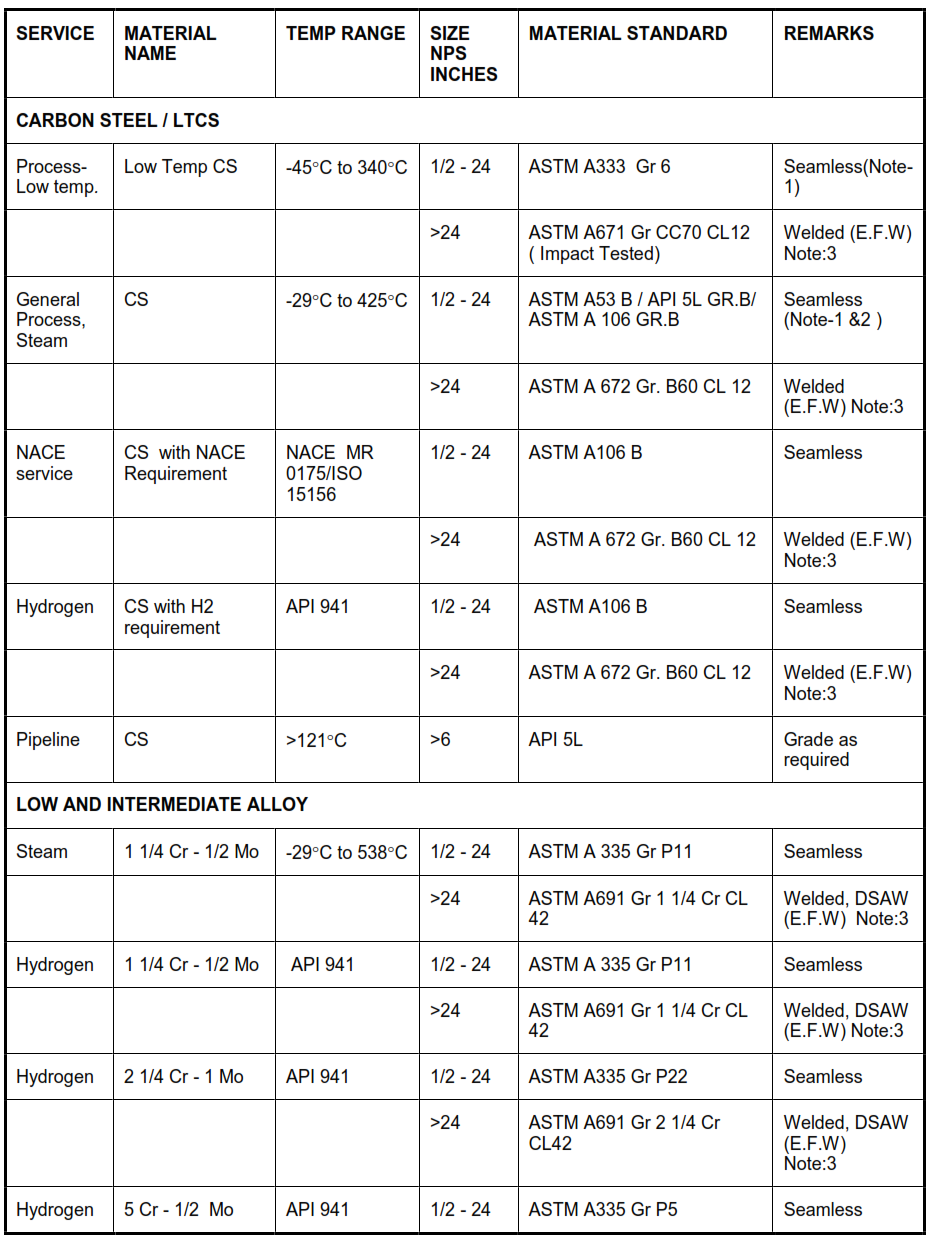

Notes
1. Use of Welded pipe instead of Seamless is permissible in case of Carbon Steel for sizes 18” &
above and in case of Stainless Steel for sizes 16” & above. This relaxation is acceptable for general
process piping classes of 150 & 300 rating only. The weld shall have straight seam & 100%
Radiographed.
2. Use only killed carbon steel (A 106 GR.B) for steam services.
3. Welded Pipe shall not have more than two longitudinal seam welds for NPS 36” & above.
10 Sample Purchase Description
The Purchase Description is the means of conveying all of the information to purchase,
inspect, and warehouse the item. Vendors will offer items that do not meet the intent of the
requirements, so the purchaser must be able to properly interpret the description.
The following information shall be included in the Purchase Description:
a. Pipe
b. End
(i) Seamless or welded
(ii) Joint Efficiency
(iii) Seam
c. Material
d. Material Grade
e. Additional material and testing requirements; if applicable
f. Nominal size of pipe
g. Wall thickness as defined by schedule, weight or actual decimal wall.
h. Additional requirements