Below are main topics list to be covered in this article are
1. SCOPE
2. REFERENCES
3. GENERAL
4. SAFETY
5. MATERIALS
5.1 Equipment
5.2 Auxiliary Equipment
5.3 Electrodes
6. EXECUTION
6.1 Joints
6.2 Assembly
7. APPLICABLE STANDARD CODES
8. INSPECTION
FIGURES
1 Typical Shielded Metal Arc Welding (SMAW) Process (Coated Electrode)
2 Open Square Butt Joint
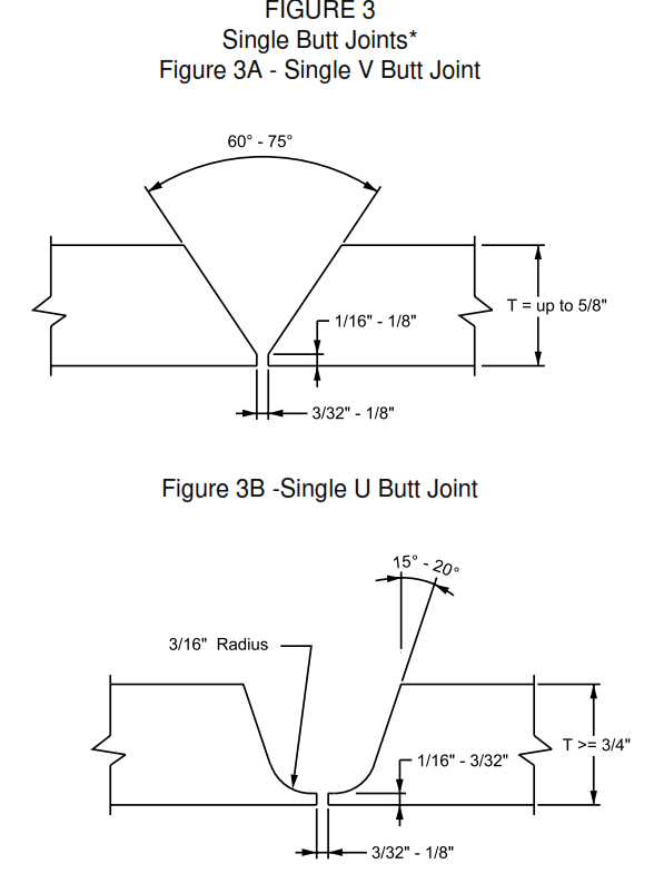
3 Single Butt Joints
3A – Single V Butt Joint
3B -Single U Butt Joint
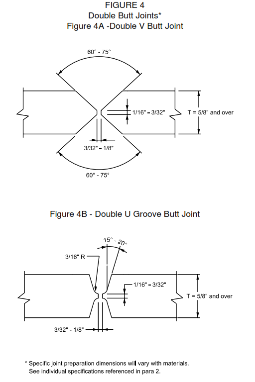
4 Double Butt Joints
4A -Double V Butt Joint
4B – Double U Groove Butt Joint
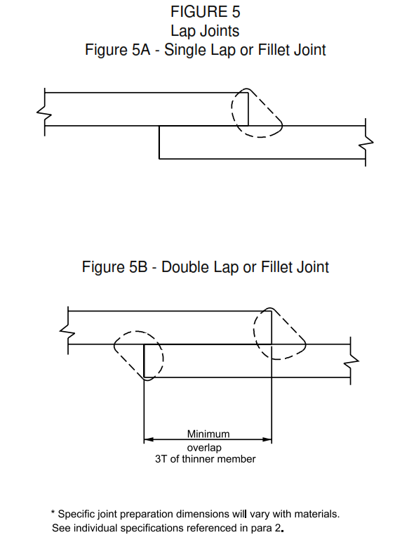
5 Lap Joints
5A – Single Lap or Fillet Joint
5B – Double Lap or Fillet Joint
6 Tee Joints
6A – No Bevel
6B – Single Bevel
6C – Double Bevel
Shielded Metal Arc Welding with Coated Electrodes | SMAW
1. Scope
This article is about general practices for shielded metal arc welding.
2. References
American Petroleum Institute (API)
620 Design and Construction of Large, Welded, Low-Pressure Storage Tanks
650 Welded Steel Tanks for Oil Storage
American Society of Mechanical Engineers (ASME)
B 31.1 Power Piping
B 31.3 Process Piping
Section VIII Rules for Construction of Pressure Vessels
3. General
3.1 Coated electrode or stick-electrode welding, is a process wherein fusion is obtained by the heat of the arc maintained between a metallic electrode and the workpiece. As welding proceeds, the electrode melts, providing filler metal, fluxing action and a protective slag. See Figure 1 for a typical representation of this process.
3.2 The self-contained simplicity of the SMAW process makes it ideal for the out-of-position work and hard to get at locations that typify field welding. However, this simplicity also limits its flexibility and makes it essential to exercise superior control of joint angle, rootface and fit-up tolerances, in order to obtain good welds.
3.3 This process utilizes a constant-current power source as described in SES W01-F07, and suitable cables to connect power source to workpiece and electrode holder.
3.4 For the specific procedure covering the material and welding process to be used in the metal joining operation, see SES W01-F02.
4. Safety
Safe practices prescribed in SES W02-F01 shall be followed on plant sites.
5. Materials
5.1 Equipment
5.1.1 The equipment requirements to control the electric arc for welding consist of the following.
5.1.1.1 A generator, either motor or engine driven, or a transformer with or without rectification, which provides current suitable for welding. Power sources are available for manual stick-electrode welding with amperages up to 600. Open-circuit voltages are limited to 75 for Alternating Current (ac) and usually 80 for Direct Current (dc). Provision is made on industrial-type machines for load voltages up to 40. Light-duty types are usually rated for a load voltage of 30. Power sources are described in SES W01-F07.
5.1.1.2 Cables are provided to connect one of the power source terminals to the workpiece, the other to the electrode holder. Cables are sized for maximum load anticipated.
5.1.1.3 A ground clamp is connected to the cable which connects the power source to the workpiece. This facilitates good electrical contact to the work. This ground clamp is attached to the workpiece as close to the joint as possible.
5.1.1.4 Arc-blow can often be controlled by the location of the ground clamp. The ac welding processes do not experience arc-blow.
5.1.1.5 An electrode holder is connected to the electrode cable and is used as a convenient means of gripping the electrode and providing good electrical contact during welding. The holder is provided with a handle so that the welder may manipulate the electrode to obtain the desired arc and weld-pool characteristics.
5.2 Auxiliary Equipment
5.2.1 Auxiliary tools and equipment include chipping hammers and wire brushes, which are used to remove spatter and slag from the weld beads.
5.2.2 Grinding or gouging equipment is sometimes needed to remove defects, enlarge the groove, grind out stops and starts, and make space for the next pass.
5.3 Electrodes
The selection of the proper electrode for a given application is fully described in SES W05-F18 for carbon steels. For other metals, electrodes are described in SES W-F standards. Reverse polarity, that is, electrode positive, work negative, is used for arc welding with coated electrodes using dc. Some electrodes, however, have coatings formulated for use with ac.
The coated electrodes are supplied in sealed containers. Electrodes are pre-heated before use to drive out moisture.
6. Execution
6.1 Joints
6.1.1 General – As indicated under 3.2 the Shielded Metal Arc Welding (SMAW) process requires better control of joint preparation tolerances than does the Gas Tungsten Arc Welding (GTAW) or the Gas Metal Arc Welding (GMAW) processes. The SMAW process provides weld quality that is essentially limited by the joint preparation. Specific joint preparation dimensions will vary with material selection. See individual specifications referred in 3.4, in addition to Figures 2, 3, and 4. For pipe alignment, see ASME B 31.1 and B 31.3.
6.1.2 Butt Joints – The joint design and angle of bevel is important because of the effect on quality and cost of welding. Most butt joints of the beveled-edge type are made using a 75-degree included V angle. The root of the bevel joint shall be provided with a land or shoulder 1.6 to 2.4 mm (1/16 to 3/32 inch) thick. If this shoulder is not provided, and there is a sharp edge, it will melt away and cause difficulty in controlling the weld penetration. A root opening shall be provided by tack welds to prevent weld contraction from closing the joint as welding progresses. Tack welds shall be feathered. Information on joints which follows is of a general nature.
6.1.2.1 Open Square Butt Joint – For material thickness of 3 mm (1/8 in) or less, the open square butt joint can be made satisfactorily, see Figure 2.
6.1.2.2 Single V and Single U Butt Joints – The single V butt joint is used for materials above 3 mm (1/8 in) and up to 16 mm (5/8 in) thick when accessible from only one side. For heavier thicknesses accessible from only one side, the extra machining of the single U groove is justified on the basis of the reduced amount of weld metal required to fill the groove. Joint design for single V and single U joints is shown in Figures 3A and 3B.
6.1.2.3 Double V and Double U Butt Joints – The double V or double U butt joint is recommended for heavier plate thicknesses where the joint is accessible from both sides. Figures 4A and 4B shows these joints.
6.1.3 Lap Joint – The lap- or fillet-type joint as shown on Figure 5A, is the least desirable type of joint, as it offers little resistance to bending in flat plates or sheets. A double lap weld, as shown on Figure 5B, results in a more rigid joint.
6.1.4 Tee Joint – Joint details are shown on Figures 6A, 6B, and 6C for the fillet welds. In many cases, no preparation is necessary and a double-welded tee joint as shown in Figure 6A is adequate. Where full penetration is necessary, and access is from one side only, the joint shown on Figure 6B shall be used. If access to the joint may be had from both sides, the joint used on Figure 6C is preferred.
6.2 Assembly
6.2.1 Essential to the production of satisfactory SMAW weldments are: proper pipe fit-up through inside diameter (ID) machining, or expanding or rotation of pipe to match wall thickness, plus proper attention to tack weld quality and feathering.
6.2.2 Welds made under the jurisdiction of recognized Codes shall meet alignment tolerances of the applicable code. Otherwise the pieces to be joined to provide plate alignment within 25 percent of the material thickness or 3 mm (1/8 in), whichever is less. Tack welds shall be made by qualified welders only, as per applicable procedures, with full penetration unless otherwise specified. All cracked tack welds shall be removed. Ends of tacks shall be feathered by grinding.
7. Applicable Standard Codes
Tack welding and welding of alignment clamps shall be by qualified welders in accordance with applicable welding procedures. The following codes are the guidelines for Fabrication, Execution and Testing Requirements.
| APPLICABLE WELDING CODES | |
| Pipe | ASME 31.1, 31.3 |
| Tank | API 620 and 650 |
| Plate | ASME Section VIII |
8. Inspection
8.1 The amount and type of inspection required depends upon the service conditions and hazards to personnel and property. It is the responsibility of the originator to define the inspection requirements. Inspection shall be in accordance with applicable code(s).
FIGURE 1
Typical Shielded Metal Arc Welding (SMAW) Process (Coated Electrode)
FIGURE 2
Open Square Butt Joint*
* Specific joint preparation dimensions will vary with materials. See individual specification referenced in para 2.


