What is Starter Motor?
A starter motor is an electrical device that is designed to control the operation of an electric motor. It provides a means to start, stop, and protect the motor from various electrical and mechanical issues. Starters motor are crucial components in industrial and commercial applications where electric motors are used.
The primary functions of a starter motor include:
- Starting: Starters motor enable a controlled and safe way to initiate the operation of an electric motor. They gradually apply power to the motor’s windings, which helps prevent sudden inrush currents that can damage the motor or the power supply.
- Stopping: Starters motor provide a means to stop the motor’s operation when needed. This can be done by opening the electrical circuit that supplies power to the motor.
- Overload Protection: Starters motor incorporate overload protection mechanisms. These mechanisms monitor the current flowing through the motor’s windings. If the current exceeds a certain level for an extended period, indicating an overload condition, the starter trips and disconnects power to prevent motor damage.
- Short Circuit Protection: Some starter motor also include short circuit protection to prevent damage in case of a short circuit in the motor’s electrical circuit.
- Reversing: In applications where motors need to operate in both forward and reverse directions, reversing Starters Motor are used. These starters allow for the reversal of motor rotation by switching the polarity of the power supply.
Starters motor can come in various types, ranging from simple electromechanical contactors combined with overload relays to more advanced solid-state starters with electronic protection and control features. The choice of starter motor type depends on factors such as the motor’s size, the application’s requirements, and the level of protection needed.
A starter motor is an essential electrical device used to control the starting, stopping, and protection of electric motors in various industrial and commercial applications. It helps ensure the safe and efficient operation of motors while preventing damage caused by excessive current, voltage fluctuations, and other electrical issues.
Working Principle of Starter Motor
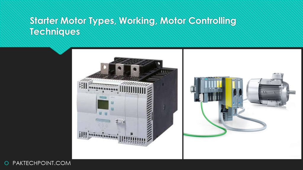
In many motor applications, remote control devices are needed to start and stop the motor. Magnetic contactors, like the ones shown below, are commonly used for this purpose. These contactors are also used to manage power distribution in lighting and heating circuits.
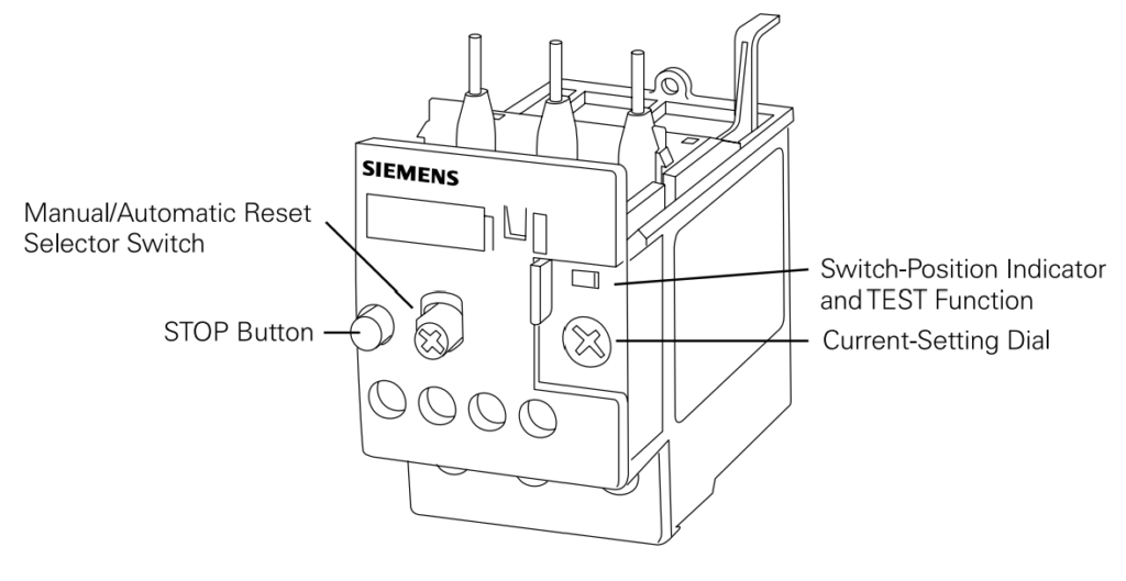
While contactors are great for starting and stopping motors, they lack the ability to detect when a motor is overloaded. This is where overload relays come in. Overload relays, as shown below, provide protection against motor overload by using heaters and bimetal strips to sense excessive current flow.
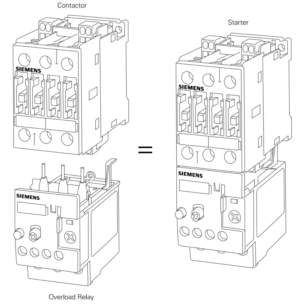
It’s important to note that contactors and overload relays are separate devices. When combined together, they form what is known as a motor starter.
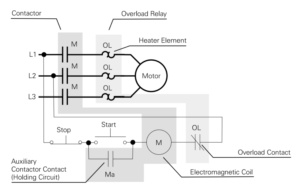
The diagram below illustrates the electrical relationship between a contactor and an overload relay. The contactor, shaded in darker grey, contains the electromagnetic coil, main motor contacts, and auxiliary contacts. The overload relay, shaded in lighter grey, includes the “OL” heaters and overload contacts. Additional contacts, known as auxiliary contacts, are also present in both the contactor and the overload relay for use in the control circuit. For instance, a normally closed “OL” contact is connected in series with the “M” contactor coil and L2, while a normally open “M” auxiliary contact (“Ma”) is connected in parallel with the “Start” pushbutton.
Starter Motor Types:
At the core of a combination motor control center lies the starter motor, which serves as its heart. The primary type of starter used is the full-voltage starter, composed of two key components: a contactor and an overload relay.
The contactor plays a crucial role in the starter motor. It serves as a remote switch, allowing the motor to be started and stopped from a distance. On the other hand, the overload relay serves as a protective feature, safeguarding the motor from instances of overloading.
Although full-voltage starters are the most common, there are various other types of starters available for specific purposes. In the context of tiastar motor control centers, the following starter types are options:
Brief explanation of each of these starter motor types:
- FVNR (Full-Voltage, Non-Reversing): This type of starter motor allows full voltage to be directly applied to the motor. It is used when the motor needs to run in only one direction, without the need for reversing its rotation.
- FVR (Full-Voltage, Reversing): Similar to FVNR, but this starter allows for reversing the motor’s direction by switching the polarity of the applied voltage. It’s used when a motor needs to run in both forward and reverse directions.
- 2S1W (Two-Speed, One Winding, Reconnectable Consequent Pole Unit): This starter is designed for motors with two different operating speeds and a single winding. It achieves different speeds by changing the number of poles used in the motor, usually through a reconnectable consequent pole unit.
- 2S2W (Two-Speed, Two Winding): Similar to 2S1W, but this starter employs two separate windings in the motor to achieve different speeds.
- PW (Full-Voltage, Part Winding): Used for motors with two separate windings. This starter initially starts the motor with only a part of the windings, reducing the starting current. After a certain time or condition, it switches to full winding.
- RVAT (Reduced-Voltage Auto-Transformer – Closed Transition): This type of starter reduces the voltage applied to the motor during startup, which lowers the starting current and torque. It uses an auto-transformer and allows a smooth transition to full voltage once the motor reaches a specific speed.
- YD (Wye Delta – Open or Closed Transition): The YD starter is used with motors having six leads. It starts the motor in a wye configuration, reducing voltage and current during startup. After a certain time or condition, it switches to a delta configuration for full-speed operation.
- RVSS (Reduced-Voltage Solid State – Soft Starter): This is a modern solution for reducing the inrush current and torque during motor startup. It uses solid-state electronics to gradually ramp up the voltage to the motor, providing a smoother start.
- VFD (Variable Frequency Drive): A highly versatile starter that allows precise control of motor speed and torque by adjusting the frequency of the supplied power. This can lead to energy savings and better control in various applications.
These various starter types cater to different motor control requirements, such as direction control, speed control, and reducing inrush current during startup. The choice of starter depends on the specific needs of the application and the motor being used.
Each of these starter types serves a specific purpose in controlling motors under different conditions. For example, a VFD (Variable Frequency Drive) enables the adjustment of the motor’s speed by altering the frequency of the power supplied to it. This can result in energy savings and more precise control over the motor’s operation.
In summary, starter motor are vital components in motor control units, allowing remote start/stop functionality and motor protection. Various types of starters, including full-voltage and specialized options, cater to different motor control needs. The VFD, in particular, offers the ability to control a motor’s speed by adjusting the frequency of the power input.
Full-voltage starters
Full-voltage starters, also known as across-the-line starters, are so named because they initiate the operation of an induction motor by directly applying the full voltage of the power line to the motor’s stator windings. This happens when the contacts within the Starter Motor contactor close.
When these contacts close, the current that flows through them also flows through the starter’s motor overload relay. The primary purpose of the overload relay is to ensure the motor’s protection. It is designed to sense and respond to instances of overload, disconnecting the power supply in case the motor draws excessive current. This protection mechanism prevents damage to the motor under abnormal conditions.
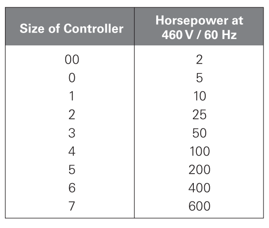
Contactor units and starters that are employed in tiastar motor control centers are rated according to the standards set by the National Electrical Manufacturers Association (NEMA). These units are available in various sizes, ranging from size 00 to size 7. This range of sizes accommodates a wide spectrum of motor horsepower ratings, spanning from 2 HP (horsepower) to 600 HP at a voltage of 460 volts.
In essence, full-voltage starters are named after their method of operation, directly applying full line voltage to the motor to initiate its motion. The inclusion of overload relays, along with standardized sizes for components, ensures effective motor protection and compatibility across various motor control applications.
Overload Relay Trip Classes
Certainly, I can explain overload relay trip classes:
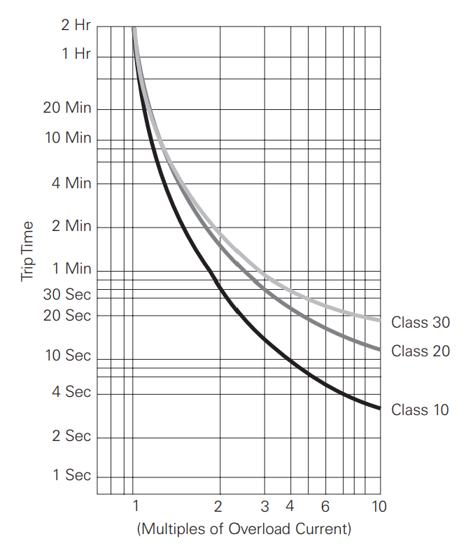
Overload relays are equipped with trip classes that determine the duration it takes for the relay to activate in response to an overload condition in a motor. These trip classes are essential for ensuring that the motor is safeguarded against prolonged overcurrent situations. The most common trip classes are Class 10, Class 20, and Class 30.
For instance:
- Class 10: This trip class indicates that the overload relay will trigger within 10 seconds or less when an overload condition is detected. Specifically, it will activate at around 600% of the motor’s full load amps. This duration is often sufficient for the motor to achieve its full operating speed. Class 10 is suitable for various applications where the motor’s startup time is relatively quick.
- Class 20: With this trip class, the overload relay responds within 20 seconds or less at around 600% of full load amps. While slightly slower to trip than Class 10, it provides extra time for the motor to handle situations where startup might take a bit longer.
- Class 30: Class 30 overload relays take up to 30 seconds or less to trip at 600% of full load amps. This longer duration is often necessary for industrial loads with higher inertia, where more time is required for the motor to reach its full speed. The extended time helps prevent unnecessary tripping due to temporary startup surges.
Siemens, as you mentioned, offers overload relays designed to meet these different trip classes (Class 10, 20, and 30), catering to various industrial needs and the specific requirements of motor applications. Selecting the appropriate trip class is crucial to ensure that the overload protection matches the motor’s characteristics and the demands of its intended operation.
Class 14 NEMA Starters
Following is explanation of Class 14 NEMA Starters and their features:
Class 14 NEMA Starters:
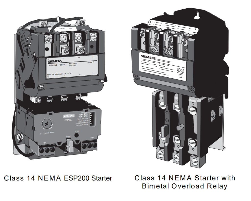
In tiastar motor control centers, starters can be equipped with either an ambient-compensated thermal overload relay or a solid-state overload relay. Class 14 NEMA starters that come with a thermal overload relay are available in NEMA sizes 00 through 4. This range also includes fractional sizes like 1¾, 2½, and 3½, and they are suitable for motor applications up to 100 HP (horsepower). These starters are designed with either a Class 10 or a Class 20 ambient-compensated bimetal overload relay.
Class 14 ESP200 Starters:
Class 14 ESP200 starters utilize the same contactors as the Class 14 NEMA starters equipped with a thermal overload relay, covering NEMA sizes 00 through 4. However, instead of a thermal overload relay, these starters come with an ESP200 electronic overload relay. Additionally, ESP200 starters are available in tiastar motor control centers with contactors up to and including NEMA size 7.
ESP200 Electronic Overload Relays:
ESP200 electronic overload relays, which are used in Class 14 ESP200 starters, have several notable features:
- Heater Elimination: Unlike traditional overload relays that require heaters, electronic overload relays like the ESP200 do not need them.
- Full-Load Ampere (FLA) Dial: These relays include an FLA dial that allows adjustment within a wide range (4:1) to match the specific motor application’s requirements.
- DIP Switches: ESP200 electronic overload relays have two dual in-line package (DIP) switches accessible from the front. These switches help simplify the selection of trip classes (5, 10, 20, and 30). Additional DIP switches allow for the choice between manual or automatic reset, and they determine whether the ESP200 will trip in response to phase unbalance, phase loss, or ground faults.
- Front Accessible Buttons: The RESET button, used for manual reset when selected, and the TEST button, which triggers a complete electronic functions test, are both accessible from the front of the relay.
In summary, Class 14 NEMA starters offer options with both thermal overload relays and electronic overload relays like the ESP200. These relays provide advanced features such as adjustable trip classes, elimination of heaters, and easy accessibility for testing and configuration. They are designed to offer enhanced control and protection for motors within various industrial applications.
SIMOCODE pro Motor Management System:
The SIMOCODE pro Motor Management System is a versatile solution used in tiastar motor control centers to provide comprehensive motor protection and control. Here’s an overview of its features and capabilities:
SIMOCODE pro Overview:
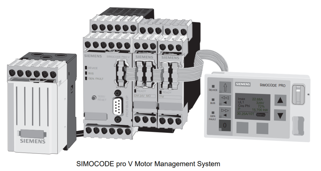
The SIMOCODE pro Motor Management System is designed to offer solid-state protection and multifunctional capabilities for constant speed motors. It is a flexible and modular system that integrates motor protection, control functions, operational tracking, diagnostics, and statistical data collection. Communication with the automation system is facilitated through PROFIBUS DP, a popular industrial communication protocol.
SIMOCODE pro C:
SIMOCODE pro C is a compact and cost-effective version of the system. It is intended for use with full-voltage forward and reversing starters. Each SIMOCODE pro C unit consists of a basic unit connected via a single cable to a current measuring module. An optional operator panel can also be linked to the basic unit. This configuration provides motor protection and basic control functionalities.
SIMOCODE pro V:
SIMOCODE pro V offers an expanded set of features compared to SIMOCODE pro C. It includes:
- A basic unit
- A choice of a current measuring module or a combination current/voltage measuring module
- The capacity to accommodate up to five expansion modules
- An optional operator panel (with or without a display)
Expansion modules are available to enhance the capabilities of the system:
- Discrete Input/Output Modules: These modules enable digital input/output connections to interface with external devices.
- Analog Input/Output Modules: Analog modules allow the system to handle analog signals for more precise control and monitoring.
- Ground Fault Detection Module: This module detects ground faults, which can help prevent electrical hazards and damage.
- Temperature Sensing Module: This module adds temperature sensing capabilities for monitoring motor and equipment conditions.
Benefits:
The SIMOCODE pro Motor Management System offers several advantages, including comprehensive motor protection, flexible configuration options, enhanced control and diagnostic capabilities, and integration with industrial communication networks like PROFIBUS DP. The system’s modular design allows customization to match the specific needs of different motor control applications, making it suitable for a wide range of industrial scenarios.
In summary, the SIMOCODE pro Motor Management System is a versatile solution that provides advanced motor protection, control, and diagnostics within tiastar motor control centers. It comes in different versions (SIMOCODE pro C and SIMOCODE pro V) to cater to varying requirements, offering a comprehensive and customizable solution for motor management.
SIRIUS Soft Starter Motor
The SIRIUS Soft Starters are solid-state, reduced-voltage starters that play a crucial role in managing motor startup and stopping processes. They are designed to limit the initial surge of current and torque during motor startup by gradually increasing the voltage applied to the motor windings. This controlled increase in voltage, known as phase control, is achieved by adjusting the power supply cycle.
Key features of SIRIUS Soft Starters:
- Integrated Bypass Contacts: After completing the startup phase, SIRIUS soft starters utilize integrated bypass contacts to bypass the power switching devices (thyristors). This enhances efficiency, reduces heat generation, and lessens stress on these components.
- Controlled Starting and Stopping: Some models, like SIRIUS 3RW40 and 3RW44, enable the application of the phase control process in reverse during motor stopping. This controlled stopping mechanism minimizes stress on connected devices and mitigates line voltage fluctuations.
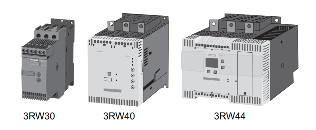
- Modular System: The SIRIUS modular system consists of different models suitable for various applications. This includes the SIRIUS 3RW30 and 3RW40 soft starters for standard applications and the SIRIUS 3RW44 soft starters for more advanced applications.
- SIRIUS 3RW30 Soft Starters: These soft starters offer a compact design that integrates seamlessly with other SIRIUS components. They are available for supply voltages up to 480 VAC and operating currents up to 106 amps at 40º C. Front-panel potentiometers allow adjustments for ramp-up time and starting voltage.
- SIRIUS 3RW40 Soft Starters: Building upon the features of 3RW30, 3RW40 models are suitable for currents up to 432 amperes at 40 degrees C. Additional features include selectable motor overload protection (Class 10, 15, 20), manual or remote reset, optional thermistor motor protection, and integrated intrinsic device protection to prevent thermal overloading of thyristors.
- SIRIUS 3RW44 Soft Starters: These advanced soft starters cater to difficult starting applications. They offer extensive functionality and diagnostics. Operating currents can go up to 1214 amps at 40 degrees C. They feature a backlit display with 4-key operation for easy parameter changes. Notable features include motor overload protection, thermistor motor protection, selectable current limiting, multiple starting and stopping modes, intrinsic device protection for thyristors, and optional PROFIBUS DP communication.
In summary, SIRIUS Soft Starters are solid-state devices designed to control and manage motor startup and stopping processes. They provide gradual voltage increase to limit initial current surges and offer various models with features tailored to different application needs, from standard to more advanced industrial scenarios.
Variable Frequency Drives (VFDs) as Starter Motor:
Let’s explain into Variable Frequency Drives (VFDs):
Variable Frequency Drives (VFDs):
A Variable Frequency Drive, commonly known as a VFD or AC drive, is an electronic device used to control the speed of an AC motor. However, its capabilities can extend beyond just speed control, depending on the specific drive and application needs. These drives are particularly applicable when controlling AC induction motors, where the motor’s speed is directly influenced by the frequency of the AC power supplied to it.
AC Drive Terminology:
- Speed Control: One of the primary functions of a VFD is to precisely control the speed of the connected motor. By adjusting the frequency and voltage of the power supplied to the motor, a VFD can regulate the motor’s rotational speed.
- Other Control Capabilities: Depending on the model and application, a VFD might have the ability to control other motor-related quantities such as torque, acceleration, and deceleration.
AC Drive as VFD:
Since VFDs are widely used to control the speed of AC induction motors by altering the frequency of the supplied AC power, they are often referred to as Variable Frequency Drives. The term emphasizes their primary function of adjusting the frequency to achieve varying motor speeds.
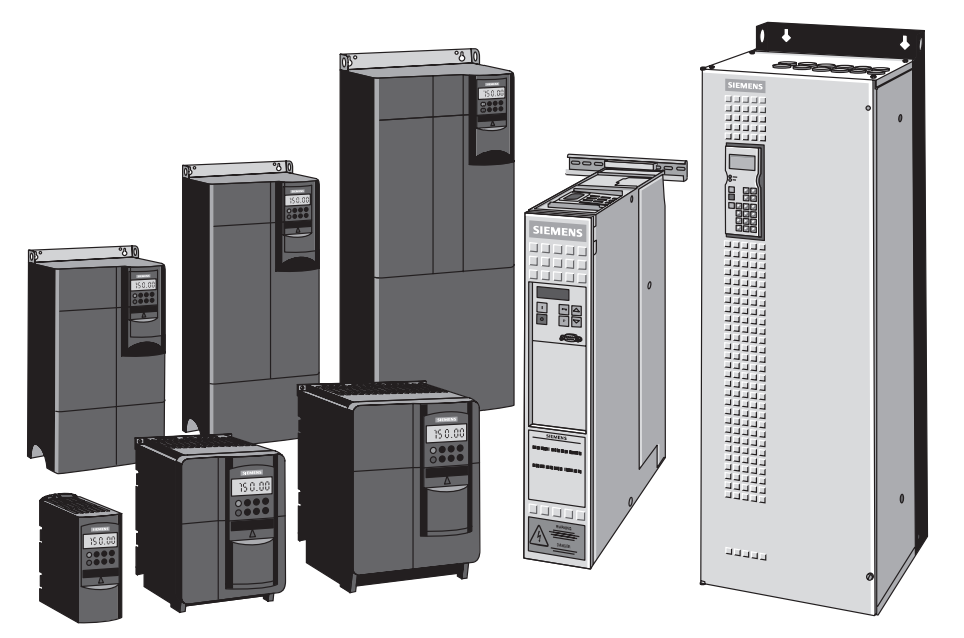
Siemens AC Drives:
Siemens offers a comprehensive range of AC drives to cater to diverse application requirements. These drives can be integrated into tiastar motor control centers, providing a versatile and efficient solution for controlling AC motors. The selection of AC drives available for integration into tiastar motor control centers is continuously expanding, ensuring compatibility with a wide variety of applications.
In summary, a Variable Frequency Drive (VFD) is an electronic device used to control AC motor speed by manipulating the frequency of the supplied power. VFDs offer precise control over motor speed and other parameters, making them essential components in industrial applications that require varying levels of control over motor performance. Siemens provides a range of AC drives suitable for integration into tiastar motor control centers, ensuring flexibility and adaptability to various application needs.
FAQs about Starter Motor
What is the purpose of an overload relay in a Starter Motor?
How do I select the appropriate Starter Motor size for my motor’s horsepower and voltage?
What’s the difference between open-transition and closed-transition Starter Motor?
Can I use the same Starter Motor for different types of motors, such as induction motors and synchronous motors?
What are the benefits of using a solid-state Starter Motor compared to an electromechanical starter?
Read Full Course of MCC Electrical Full Course in PDF.