| PURPOSE |
| SCOPE |
| APPLICABLE DOCUMENTS |
| RESPONSIBILITY |
| MANPOWER |
| TOOLS & EQUIPMENT |
| METHODS/PROCEDURES |
| QUALITY CONTROL |
| SAFETY PRECAUTION |
| ATTACHMENTS |
STEEL FRAME SHELTER ERECTION METHOD STATEMENT
1.0 PURPOSE:
1.1 This method statement shall provide ARCC minimum guidelines to erection Steel Frame Shelter in accordance with Saudi Aramco Standards and Procedure.
2.0 SCOPE:
2.1 This specification covers the minimum requirements for erection of steel frame shelter to be applied in Jazan Refinery & Terminal Project package 12 Naphtha and Aromatics.
3.0 APPLICABLE DOCUMENTS:
Specification and Standards
| 3.1.1 S-000-1630-003 | Material and Equipment Protection Program at work Site |
| 3.1.2 S-000-1520-103 | Handling Procedure |
| 3.1.3 S-000-1640-005 | Procedure for Work Release Between Disciplines |
| 3.1.4 S-000-1520-102 | Non-Conformity Control Procedure |
| 3.1.5 S-000-1520-101 | Field QC Procedure |
| 3.1.6 S-000-1650-001 | Safety Execution plan |
| 3.2 ARAMCO Project Specifications and Standard | |
| SAEP-302 | Instruction for obtaining a waiver of a mandatory Saudi ARAMCO Engineering requirement. |
| SAES-B-014 | Safety Requirement for Plant and Operations Support Buildings |
| 12-SAMSS-007 | Fabrication of Structural and Miscellaneous Steel |
| 12-SAMSS-008 | Erection of Structural and Miscellaneous Steel |
| SAES-H-101V | Approved Saudi Aramco Data Sheets – Paints and Coatings |
| 3.3 Industry Codes and Standards: | |
3.3.1 AWS D1.1 Structural Welding Codes
3.4 Inspection and Testing Plan/Method Statement
3.4.1 SATIP-M-001-01 Structural Steel-Piperack, Steel Supports & Miscellaneous* Steel Structures (* Incl. Piping Supports per Specification)
3.5 Latest Revision of the following Documents shall be used.
3.5.1 Foundation Drawing
3.5.2 Structural Standard Details
3.6 Saudi ARAMCO Safety, Health and Environmental Standard:
3.6.1 Construction safety manual — compliance with schedule D.
3.6.2 Saudi ARAMCO Safety Requirements for Scaffolds
3.6.3 General Instructions (G.l’s) at the work site.
4.0 RESPONSIBILITY:
4.1 Construction Manager is responsible for implementation of all HSE requirements; he shall study, analyze and schedule all construction activities with his department to include manpower and equipment line up as well as other possible resources required for the successful implementation of the construction work activities. Study all aspects of work procedure as per Saudi Aramco Standard and Procedures.
4.2 Structural Superintendent/ Supervisor shall study and review all necessary documents for the erection works in his area to include, technical scope of work, specification, bill of quantities, planned milestone dates and construction procedure in support to his Structural Foreman. He shall monitor the availability of materials in accordance with the schedules and construction analysis. He shall be directly reporting to the Construction Manager. He shall coordinate with other discipline to visualize possible conflicts in the drawings as well as in the schedules to provide other options in preventing unnecessary delays obstructions.
4.3 Structural Foreman shall be responsible for the direct work supervision at site and ensure that the work is performed in accordance with Saudi Aramco Standard and Procedure, and latest approved for construction drawings. He shall monitor the availability of materials in line with his required schedule.
4.4 QC Inspector shall be responsible in monitoring and inspection of the work and ensure that the work is performed in accordance with Saudi Aramco Standard and Procedure.
4.5 Safety Engineer/Supervisor shall be responsible in monitoring safety aspects and ensuring that the work is done in accordance with Saudi Aramco Construction Safety Manual. He shall discuss to the workers the characteristics of related materials and status of work area giving reminders as an additional point to work safely.
5.0 MANPOWER
5.1 The Structural Supervisor shall control the overall activity of steel worker. The basic manpower under him shall consist but not limited to the following:
- Foreman Structural
- Rigger (Aramco Certified)
- Steel Worker
- Crane Operator (Aramco Certified)
- Truck driver
- Surveyor
- Rod Man
- Helper
- Manlift Operator (Aramco Certified)
- Scaffolder (by others)
- Safety Engineer/Supervisor
- QC Inspector
6.0 TOOLS AND EQUIPMENT;
6.1 Tools and equipment needed should be in good condition and must be checked by Structural Supervisor/Safety Officer prior to use in the construction area. These Includes but not limited to:
- Calibrated engineering level with calibration certificate.
- Corrective wrenches all required range (Torque wrenches to be calibrated).
- Certified sling and hoists.
- Rigging accessories.
- Crane.
- Tag line nylon rope.
- Trailer Truck.
- Manlift.
- Air compressor.
7.0 METHODS/ PROCEDURES:
7.1 Jobsite Receiving and Inspection:
- Upon withdrawal and receipt of structure from DEC/JGC warehouse, receiving inspection shall be conducted immediately to verify compliance with the latest revision of vendors drawing, project requirements.
- If any damaged steel members are discovered or any parts components, or documentation is missing or otherwise defective, the occurrence shall be immediately reported to DEC/JGC.
- Panels delivered to site shall be inspected and approved for installation while in warehouse. Extra care shall be exercised in unloading to prevent bending, warping, twisting, and surface damage.
- Miscellaneous materials shall be provided as required for a complete roof and wall panel assembly and as recommended by panel manufacturer. Miscellaneous materials shall consist but not limited to as follows: fasteners, trims, flashings, gutters, sills, corner units, ridge closures, clips, seam covers, closure strips, sealants.
- Record of Material Receiving Inspection shall be documented. Findings, deviations shall be documented in Quality control Inspection Report (QCIR) and Non Conformance Report (NCR).
7.2 Preparatory works for erection of main structure
- Confirm the turnover of civil works foundation/pedestals with a signed copy of Work Release Notice as per Doc. # S-000-1640-005 prior for installation of Steel Frame Shelters.
- Secure necessary work permit from DEC/JGC Representative prior to start of work/activity.
- Check foundations and other connection points to confirm locations, orientation elevation and condition.
- Prepare all materials, equipment and tools needed for the job.
- Prepare Assembly Lift Plan that contain detailed data on the extent of the lifted assembly, its weights, the structural calculations that show structural stability of the assembled components during lifting operations, verifications of the capacity capabilities for any cranes utilized in the lift, location and positioning of the cranes, and a description of the rigging to be utilized.
- Check wind condition, lift shall not proceed when wind velocity is greater than manufacturers recommendation or with a wind velocity of 20mph / 32kph and greater, unless otherwise specified by the crane manufacturer.
- Stabilized ground areas where crane will be located and positioned. Crane mats shall be provided in accordance to findings of soil bearing pressure.
- Use only approved lifting plan.
- Crane lift & rigging requirement shall refer to G.1.7.025, 020 & 029.
- Prior to acceptance on turnover foundation, ensure that foundation is complete with anchor bolts and it was already checked for dimensions, levelness, alignment, top of concrete elevation, surface finish, and as per latest revision of drawings and within acceptable tolerances. Conduct inspection using SAIC-M-2006.
7.3 Installation and Grouting of Packer Plates
7.3.1 Clean the top of bearing surfaces and bottom of base plates. Set and shim column base plates to correct positions, elevations, and locations as shown on the latest approved erection drawings. Shims and wedges to be used shall be provided by ARCC, setting nuts shall be loosened before grouting as per PIP STS05130 6.4.1.
7.3.2 Ensure that the top of foundations have been properly roughened for bonding Laitance, oil, grease, dust, sand and other foreign matter shall be removed if any.
7.3.3 Dry Pack Grouting;
-
- Contractor shall conduct one (1) time sampling/testing for dry pack grouting during setting of packer plates to ensure compressive strength of grout materials conforms to requirements.
- Mixture of grout to be used for installation of packer plates shall be dry pack “non-shrink cementitious grout” in accordance with manufacturer’s recommendations.
- Sampling, curing and testing grout specimen shall follow procedure as specified in Non-shrink Grout Installation.
- Setting of packer plates or other adjusting devices shall be in a manner that will ensure structural members are located in correct positions and elevations.
- Install packer plates (100x80x10mm thk.) in location(s) as applicable in-between anchor bolts of concrete pedestal. Packer plates will be coated as pet applicable coating system schedule. Grade of packer plate shall be ASTM A36/ASTM A36M as per 12-SAMSS-007 sec. 4.2.
- Conduct inspection for elevation and location of installed packer plates
- Upon acceptance and curing of dry pack grout installation and packer plates setting, erection of shelter main member shall commence.
7.4 Preassembly and Erection of Framework
7.4.1 All materials and equipments shall be place on designated area near the location for assembly and erection.
- Surface of steel structural member shall be clean by air blowing on ground prior for lifting work. Provide dunnage underneath to avoid materials on direct contact with soil and protect from dirt.
- Lifting of painted structural members shall be done with non abrasive choker.
- The crane responsible for loading or unloading structural members shall be assigned separately prior for erection works.
- Assemble structural steels by frame type and/or module type accurately conforming to the lines and elevations indicated in latest approved for construction erection and fabrication drawings and within the specified erection tolerances.
- Perform welding works on items that may require welding.
- After pre-assembly check if the bolt is already at snug tight condition by using a test hammer. Mark the bolt as applicable in Fig. 1A and Fig. 1B.
- Erection point shall either be alongside the structure near the pedestals where the frame will be erected, or in designated area outside the site erection area. Erection will progress by line. It will take place after two adjacent frames have been assembled and every frame done thereafter until the works reach the last bay.
- Position mobile crane (capacity as required) on the assembly and erection area.
- Erect the assembled steel framework on its assigned pedestal. Tighten the nuts of anchor bolts. Attach two wire ropes at the center of the uppermost column with sufficient lengths for use as guy lines and fix it in opposite directions (one due west and the other due east).
- Then, install all connecting tie beams and/or braces inclusive on each bay, it shall be completely established to attain stability of the erected frame.
7.5 Pre-alignment of Steel Structure
7.5.1 After completion of steel erection, plumbness checking and alignment of erected structure shall commence from Grid lines until the alignment and plumbness of all columns have been checked and corrected. QC inspection shall verify alignment and plumbness records as per SATIP-M-001-01.
7.5.2 Alignment inspection for completed steel structure shall be done prior to welding and final bolt tightening; steel structure shall be totally inspected for accuracy of construction and to ensure that all dimensions are as specified.
7.5.3 Inspection records shall be prepared by ARCC and shall be submitted to JGC for approval and signing.
7.6 Bolt Tightening
7.6.1 After QC inspection and acceptance of pre-alignment records, bolt tightening shall be done at all Gridlines of steel frames. Refer to (7.8 Detailed Procedure on Bolt Tightening).
7.7 Platforms and Access-ways assembly and installations
7.7.1 Platforms and access-ways shall be installed after the steel frame structure is fully erected.
7.8 Detailed Procedure on Bolt Tightening
7.8.1 Bolt Connections I General Requirements
7.8.1.1 ASTM A325M bolts shall not be reused.
7.8.1.2 Where ASTM A307 bolt assemblies are used for connecting miscellaneous items (i.e., handrail assemblies, pipe supports, gates, etc.) to structural members, the bolts shall be tightened to snug tight condition.
7.8.1.3 Contractor shall color code the ends of the tightened bolts by placing a yellow paint mark indicating that the bolts have been properly tensioned and are ready for inspection.
7.8.1.4 Contractor shall initiate form SAIC-M-2009 to JGC QC for Bolt Tightening Inspection and Testing.
7.8.1.5 Enlargement of bolt holes for the correction of misalignment shall be by reaming or drilling only. Flame cutting, burning shall subject to JGC approval.
7.8.1.6 The mill certificates for the faster materials shall meet ASTM specification.
7.8.1.7 Prior to commence work, impact wrench shall be properly calibrated to desired tension using bolt tension calibrator.
7.8.1.7.1 Calibration of bolt tension calibrator shall be in every six (6) months or stringent requirements of schedule Q-IV-4, Sec.
6.1 shall apply.
7.8.2 Bolt Tightening Condition
Tightening condition shall be in accordance with 7.8.4 & 7.8.5 as noted in the standard drawings (0-000-1330-001).
Bolt applicable used for the bolt tightening procedure shall be ASTM A325M for M20, M24 and M30
7.8.2.1 This tightening method should be applicable for the various types of structures connection details as specified in the drawings, and various structure IFC drawings and various structure IFC drawings as indicated as the following abbreviation.
7.8.2.2 Type of connection for Snug Tight condition
7.8.2.2.1 S*(** such as L, S, R, RL), CS, CSF, LT, HY, LTE, HYE, HYI, H, K, V, EJ, IJ; Structure member (e.g. UB25431• SL).
7.8.2.2.2 No additional or excess tightening force shall be applied to the bolts where snug tight condition has been confirmed.
7.8.2.3 Type of connection for Fully Tightened Condition
7.8.2.3.1 This tightening method should be applicable for the various types of structure connection details as specified in the drawings and various structural IFC drawings as indicated by following abbreviations.
7.8.2.3.2 EM** (** such as EMTB, EMBH); Structure member (e.g. UB610140-EMB).
Bolt Tightening Methods
7.8.3 Snug Tight Procedure
7.8.3.1 Check the fastener assemblies (bolt, washer and nut) combination, diameter, length and grade to be used in the connection of joints.
7.8.3.2 Aligned all bolt holes for the insertion of bolts to avoid damage to the threads.
7.8.3.3 Placed bolts in all holes with washers positioned and nuts threaded to complete assembly by finger tight.
7.8.3.4 By using ordinary spud or manual wrench, the ironworker shall equally tighten the bolts and nuts until the connected piles are in firm contact, but not necessarily continuous contact.
7.8.3.5 There must be no gaps between the layers of steel where bolts penetrate the steel, these gaps must be away from the bolt holes, 25mm minimum contact around hole, but not less than the bolt diameter.
7.8.3.6 Tightening shall progress systematically from the rigid part of joint to its free edges. Secure loose bolt among bolt assembly.
7.8.3.7 Re-tightening bolts as per above procedures shall not be considered as reuse.
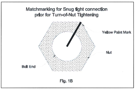
7.8.3.8 To confirm whether the bolt connection is in snug tight condition, the protruding end of the bolt and nut shall be marked by yellow paint as shown in Fig. 1A and Fig. 1 B to indicate that the bolts have been properly tightened after inspection by test hammer.
For S* (** such as L, S, R, RL), CS, CSF, LT, HY, LTE, HYE, HYI, H, K, V, EJ, IJ; Structure member (e.g. UB254x31-SL)
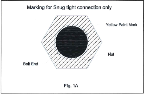
For EM (such as EMTB, EMBH); Structure member (e.g. UB610x140• EMB)
7.8.3.9 In case snug tightening shall be done using impact wrench, the following procedure specified in “Pre-tensioning Procedure Verification Testing” shall be done prior to commencement of the work.
7 .8.3.10 Tighten the nut to the value pre-set on impact wrench.
7.8.3.11 Confirm match-matched connection following procedure in Fig. 1 B
7.8.4 Fully Tightening by “Turn of Nut” Method
7.8.4.1 Prior to the application of Turn of Nut pre-tensioning, the bolted joint assembly shall be in snug tight condition.
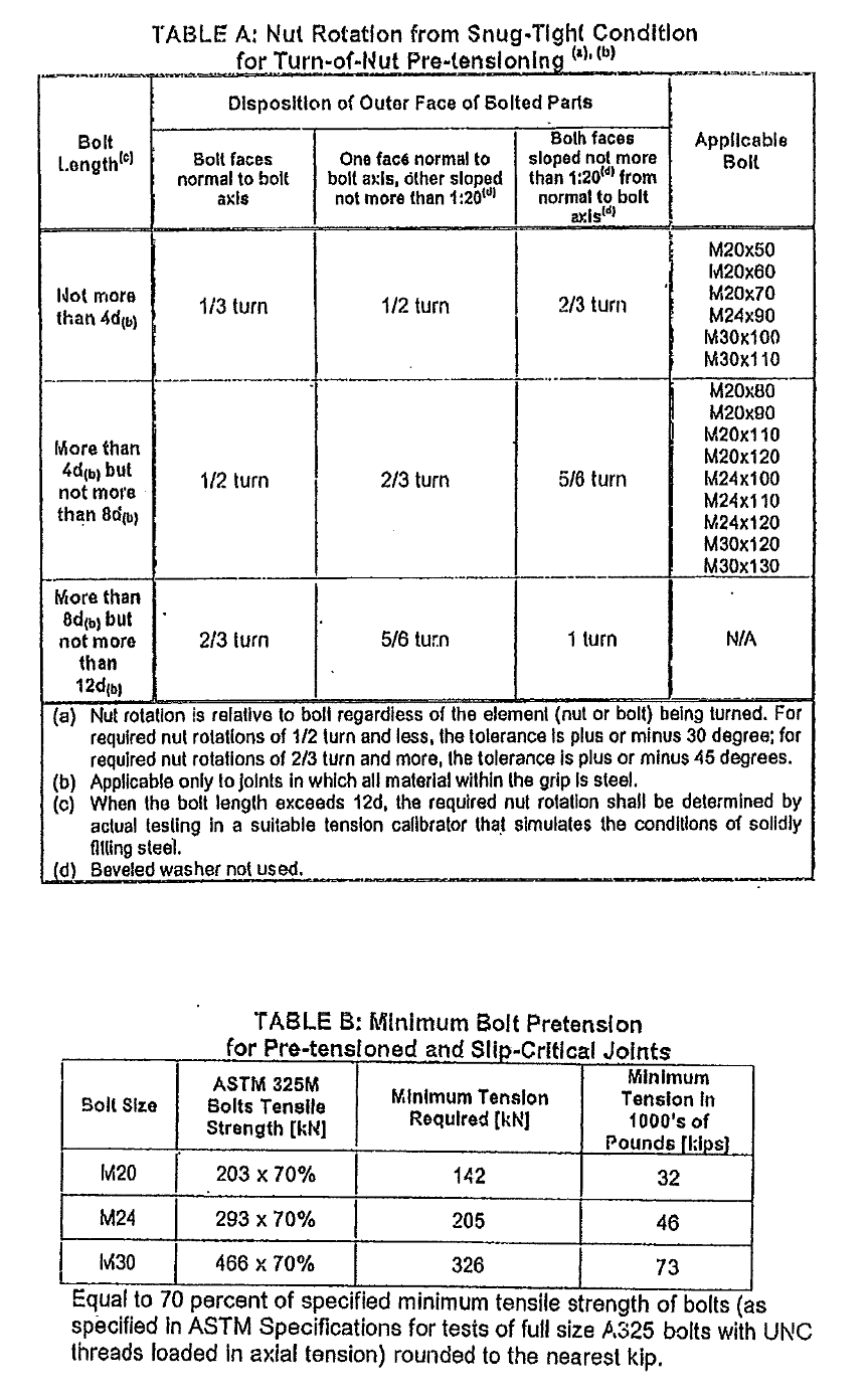
7.8.4.2 After all bolts are in snug tight condition and match-marked, the nut or bolt head is rotated the amount of turn specified in Table A (refer to attachment B).
7.8.4.3 Rotation of the nut or head is applied to all fastener assemblies in the joint, progressing systematically from the most rigid part of the joint in a manner that will minimize relaxation of previously pre-tensioned bolts.
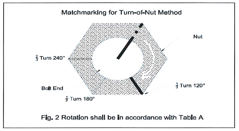
7.8.4.4 To confirm if the bolt is in Turn-of-Nut condition and properly tensioned, see Fig. 2 as illustrated.
7.8.5 Calibrated Wrench Pre-tensioning Method
7.8.5.1 The pre-installation verification procedures specified in Section 7 of “Specification for Structural Joints Using ASTM A325 or A490 Bolts” shall be performed daily for the calibration of the installation wrench.
7.8.5.2 Torque values determined from tables or from equations that claim to relate torque to pretension without verification shall not be used.
7.8.5.3 The installation torque determined in the pre-installation verification of the fastener assembly shall be applied to all bolts in the joint, progressing systematically from the most rigid part of the joint in a manner that will minimize relaxation of previously pretension bolts. The part not turned by the wrench shall be prevented from rotating during the operation. Application of the installation torque need not produce a relative rotation between the bolt and nut that is greater than the rotation specified in table 8.2 of “Specification for Structural Joints Using ASTM A325 or A490 Bolts”.
7.8.5.4 Prior to installation of fastener assembly, confirm if the tension calibrator is properly calibrated, pre-tensioning demonstration shall be conducted to confirm the sequence of work.
7.8.5.5 Take three (3) representative samples of complete fastener assemblies (bolt, nut and washer) of each combination of diameter, length, and grade and lot to be used in testing activity.
7.8.5.6 Assemble the first set of bolt, washer and nut combination into a tension calibrator, and then tighten the bolt on snug tight condition.
Match mark the bolts and nuts as shown in Fig. 1B.
7.8.5.6.1 Snug tight is defined as the tightness that exists when the plies of the joint are in firm contact. This may be attained by a few impacts of an impact wrench or the full effort of a man using ordinary spud wrench.
7.8.5.6.2 The test shall be verified that the pre-tensioning method develops a pretension that is equal to or greater than
1.05 times the tension required by Table B (refer to attachment B).
7.8.5.6.3 Remove the assembly and repeat the procedure until all three (3) samples have been tested.
7.8.5.6.4 Verification and inspection shall be conducted in accordance with SATR-M-2002 to M20, M24 and M30 bolts.
7.8.5.6.5 Visual inspection after pre-tensioning is required to ensure that fastener assemblies are matched-mark as illustrated to Fig. 2.
7.8.5.6.6 A calibrated tension calibrator shall be onsite when tightening is to be performed on pre-tensioned joints.
7.8.5.6.7 Test report shall be prepared in accordance with SATR• M-2002.
7.8.6 Final Alignment
7.8.6.1 Prior for final grouting, final alignment inspection shall commence to ensure structure plumbness following the tolerances specified in Appendix I “Erection Tolerances” on JGC Specs, unless otherwise specified on design drawings and/or erection plans.
7.8.6.2 Conduct final alignment inspection using SAIC-M-2007
7.8.7 Final Grouting
7.8.8 Subsequently the erection and final alignment of structures is done, final grouting of pedestal shall commence to complete the erection works.
7.8.9 Preparatory Works for Roof and Wall Panels
7.8.9.1 Verify that the structure is complete and bolt tightened prior to installation of roof and wall panel. Confirm the acceptance of the structure by securing a Work Transfer Sheet (WTS) prior to start of the installation work.
7.8.9.2 Using approved drawings, verify dimension, locations, and alignment of roof and wall framing including secondary structure such as purlins, girths, angles, and channels where the panels are supported and anchored.
7.8.9.3 Any unsatisfactory conditions shall be rectified prior to panel installation.
7.8.9.4 Coordinate the availability of materials and accessories in accordance to proper sequencing of adjoining works.
7.8.9.5 Anticipate any obstructions for installation works. Position the cranes as per plan; ready the grounds and the staging areas.
7.8.9.6 Manlift shall be used for the installation and alignment works.
7.8.10 Wall Panels Installation
7.8.10.1 Using crane, lift the panel and place in its intended position
7.8.10.2Panel shall be aligned and fastened using a manlift while wall panel is lifted by another crane with one (1) to two (2) man to perform such works in order to complete installation
7 .8.10.3 Position the panels accurately on supporting framework. Adjust accordingly to final position with proper bearing before securing/fastening
7.8.10.4 After aligning, secure the panel using the specified fastener with fastener gun. Fastener location shall be as shown in drawing details.
7.8.10.5 Install the next panels in the same manner as above and as per standard drawings. Take note the correct orientation of each panel. Anticipate the requirement for lapping, end trims, joint filler
7.8.10.6 For installation between end walls and sidewalls; between walls and roof, refer to applicable details and requirements of latest drawings
7.8.10.7 For required openings, field cut to suit. Extra care drilling and cold cutting using cut-off wheel or tin snip cutter. Metal filings, drill shavings, and burrs shall be removed from adjacent surface prior to panel erection
7.8.10.8Components and accessories to complete the wall panel assembly such as clips, seam covers, and similar items shall be installed
7.8.11 Roof Panels Installation
7.8.11.1 Ensure lifelines are securely installed at rooftop. Access to rooftop through scaffold (by others).
7.8.11.2 Using a crane, lift roof panel(s) to rooftop. Sheet metal workers at the roof will receive the lifted panel(s). Worker shall position the panel(s) to its intended locations
7.8.11.3 Fix the roof panels on both sides using manlift.
7.8.11 .4 Position the panels accurately on supporting framework. Adjust accordingly to final position with proper bearing before securing/fastening
7.8.11.5 After aligning, secure the panel using the specified fastener with fastener gun.
7.8.11.6 Install the next panels in the same manner as above. Take note the correct orientation of each panel. Anticipate the requirement for lapping, end trims, joint filler and weather sealant.
7.8.11.7 At peak ridge, install the peak ridge panels as per standard drawings. Provide weather sealant in connection between ridge peak panels and roof panels if it is in drawing detail.
7.8.11.8 Components and accessories to complete the wall panel assembly such as clips, seam covers, and similar items shall be installed
7.9 Damages and Nonconformity
7.9.1 Any damages and defects and nonconformity found at site and lay down yard shall be reported immediately.
8.0 QUALITY CONTROL
8.1 QC Personnel shall be assigned to ensure the quality control requirement of the project.
8.2 QC Personnel well coordinate with DEC/JGC inspector to conduct inspection as required.
8.3 QC Inspector shall be responsible to conduct all required inspection/documentation and to ensure that all applicable requirements, codes, and standards are complied with as per SAIC/SATIP.
8.4 Contractor shall utilize the applicable SAIC for every activity.
9.0 SAFETY PRECAUTION:
Obtain the approval of the work permit from the concerned DEC/JGC Representative before starting any work.
9.1 TSTI to be conducted daily prior to execution of work.
9.2 Fire Watcher with Fire Extinguisher shall be at work area whenever there is hot work.