INTRODUCTION TO STRIP CLADDING
Cladding is a welding process in which a material with desired properties is deposited on the surface of a base material. The common C/Mn or low alloyed inexpensive base metal has mainly a load carrying function. The deposited sophisticated material imparts surface properties such as corrosion resistance, wear resistance, etc., to the substrate.
To the manufacturer of pressure vessels, surfacing techniques are getting more and more important. Components reach sizes such that their fabrication calls upon the use of clad materials.
There are different processes to obtain a clad material :
– clad plates produced by rolling which are mostly only available in standardised dimensions and grades
– explosion clad plates
– clad plates made by welding
Among all the welding processes submerged arc and electroslag strip cladding offer maximum deposition rate, better bead characteristics and trouble free operation using unsophisticated welding equipment. Strip cladding is also a very flexible process covering a very wide range of applicable materials.
The fact that in general it is used to clad finish shaped components eliminates the eventual problems arising with cold or hot forming.
The principle of strip cladding was developed about 70 years ago (the first patent was granted in the USA around 1920) but in Europe the process retained detailed attention when the nuclear industry started (late 1950’s).
The nuclear power industry needed a method whereby thick- wall pressure vessels could be given a corrosion resistant inner surface.
Several modifications of submerged-arc welding with strip have been developed mainly with a view to further increase surfacing capacity.
In the first part of this paper the SUBMERGED ARC STRIP CLADDING process will be discussed, in the second part the ELECTROSLAG STRIP CLADDING technique will be described. The influence of the working parameters will be given and the main advantages and limitations will be listed.
SUBMERGED ARC STRIP CLADDING PROCESS
Principle and main advantages
There is no essential difference between strip cladding and submerged arc welding with wire. The conventional submerged arc equipment is also suitable for strip cladding, basically the wire is replaced by a strip.
The welding head has to be modified so that the contact shoes and feed rollers will take strip instead of wire.
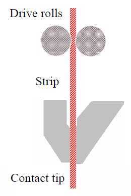
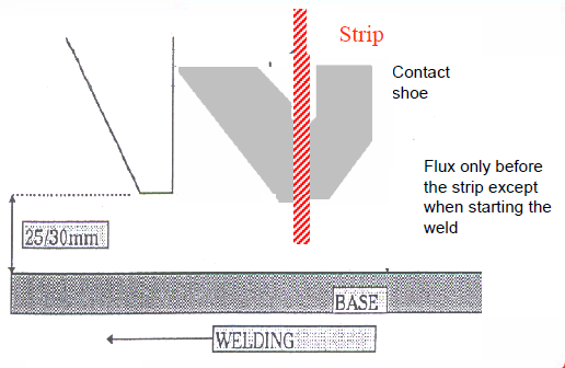
The principle of the submerged arc strip cladding process is shown in FIG.

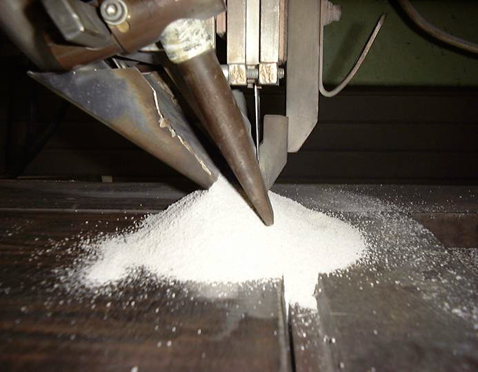
The requested energy to melt the strip and the base material is created by an electrical arc between the welding strip and the base material under a mineral flux protection.
The flux is added on both sides of the strip. During the process the strip and the base metal are continuously molten under a layer of molten flux. After solidification a shallow layer of slag covers the deposited metal.
The main advantages of the strip process over the wire processes can be summarised as follows :
– a very uniform penetration
– low penetration level and consequently low dilution levels which enables to reduce the number of layers to obtain the requested properties
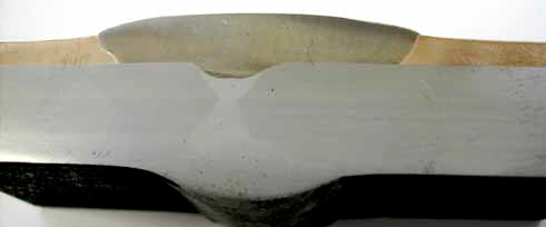
– high and consistent quality of the deposit ; the typical solidification pattern of the beads ensure a very homogeneous distribution of the alloying elements in the deposited metal
– a very low hot cracking sensitivity of classic hot cracking sensitive materials due to the absence of central solidification lines.
– very flat surface with a limited number of bead overlays
– low investment cost to switch from wire to strip
– high reproducibility
– high deposition rates
Welding equipment
- Power sources
The power source must be of sufficient capacity to cope with high currents (currents depending on strip size).
Considering the most widely used and standardised 60 x 0.5 mm strip, the power source must be able to supply direct current ranging between 600 and 1000 A at 100% duty cycle.
Constant potential power sources are very well adapted they only need a stable and independent strip feeding regulation system.
The most used power sources are CP rectifiers. - Welding head (motor and gear box) Most types of wire equipment may be used for the strip cladding process. The main factor is the ability to attach a strip nozzle.
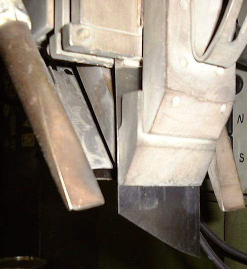
- Strip feeding nozzle he strip cladding feeding nozzle plays a major role in the stripcladding process. The nozzle guides the strip, ensures an even distribution of the welding current over the full width of the strip and has to be able to withstand and to dissipate the heat sufficiently to avoid overheating during continuous operation.
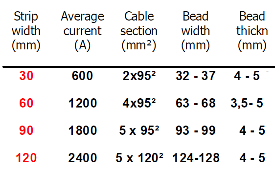
TABLE 1 lists the standard Soudometal strip feed nozzles with their major characteristics. FIGURE 3 shows the nozzle 60 DF2 (for strips up to 60 mm wide strips). - Welding strips
The strips for submerged arc strip cladding are mostly of the solid type having a width between 20 and 180 mm and a thickness of 0.4 or 0.5 mm. Typical dimensions are 30, 60, 90, 120 and 150 mm, 60 mm being the most popular one. - Main parameters – typical values
Welding current
Arc voltage
Welding speed
ELECTROSLAG STRIP CLADDING PROCESS
Principle of the process and main advantages
Electroslag strip cladding is a more recent development of the strip surfacing technique. The principle of this process has been known for a number of years and publications concerning its fundamentals were first published in the early seventy’s.
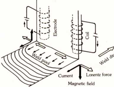
The principle of the Electroslag strip cladding process is shown in FIG and the bases is outlined as follows :

The basic principle is the following : A strip electrode is continuously fed into a shallow layer of molten electroconductive slag. The heat which is needed to melt the strip, the slag-forming flux and the surface layer of the base metal is generated by the Joule effect as a result of the welding current flowing through the liquid electroconductive slag.
The ELECTROSLAG strip process is started in the same way as a submerged arc cladding; the stabilisation of the process into the electroslag mode is reached almost instantaneously.
The typical characteristics of the process are :
– the fact that the flux is fed only on the front side of the strip
– a visible weld pool at the rear side of the strip
– a radiation only in the visible and infrared spectrum, no ultraviolet radiations because of the absence of any arc
– an additional feature (magnetic control device) is used to optimise the weld bead profile
The main advantages of the Electroslag strip cladding process can be
summarised as follows :
– the simplicity in use is very great, in principle it needs only the same type of equipment as the submerged arc strip cladding technique
– the electroslag technique offers much higher deposition rates compared to the sub arc technique, at the same level of heat inputs and similar bead thickness
– the dilution with the base metal remains very low, typicaly dilution rates are between 7 and 10 %.
– the possibility of using fewer layers to obtain the required chemical analysis (e.g. low carbon stainless steel in a single layer).
– a very stable and regular welding process with a extremely low defects risk, such as slag inclusions, lack of penetration,…
– a low flux consumption
Welding Equipment
- Power sources
In view of keeping the strip feed rate and voltage variations within very narrow limits imposed with regard to the shallow depth of the slag pool, it is advised to use DCCP rectifiers.
Since the electroslag process requires average optimised current densities of approx 40 A/mm2, the output of the power sources at a 100% duty cycle has to meet high amps such as 1250 A for a 60 mm strip (typical). In practice to obtain the required current intensity levels two power sources can be connected in parallel. It should be checked with the manufacturer
whether given DCCP power sources can be connected in parallel without any additional precautions.
To obtain optimum welding conditions and bead profile, it is necessary to use a power source which will give stable voltage outputs between 21 – 27 volts. - Welding heads
The function of the welding head is to feed the strip at a constant speed which is related to the welding parameters.
The strip feed rates for the electroslag process range from 1 to 2,5 m/min. In practice no special welding heads are required to carry out electroslag strip cladding. - Strip feeding nozzles
The main functions of the feeding nozzle are to guide the strip and to maintain it in the required position during the welding operation and to transfer the welding current from the power source to the strip by means of appropriate contact shoes. There is no fundamental difference in design between the sub arc and the electroslag feeding nozzle, however because of the high current densities involved, and due to the fact the rear side of the electroslag is subject to the heat radiation from the slag pool, their construction is generally somewhat heavier. The electroslag nozzle is also equipped with a water cooling possibility. FIG 13 shows the most classic nozzle 125 ES1-300 which can be used with strip widths from 30 mm up to
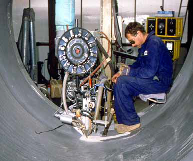
120 mm width. - Magnetic steering device
As mentioned previously, the slag pool is electroconductive, therefore, the slag pool is subjected to electromagnetic forces which tend to make it flow from the sides towards the centre of the molten pool. This results in narrower beads, more unfavorable wetting angles resulting in a more difficult slag removal and increased risks from undercut.
To compensate this phenomenon, magnetic steering devices are used. These magnetic field control systems works as following : an external magnetic field generating forces of the same nature is applied but in the opposing direction.
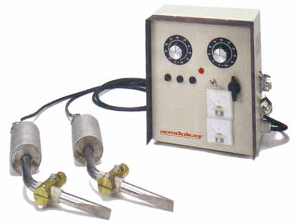
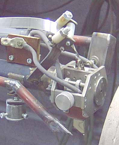
The external magnetic field is created by means of two solenoids,a picture of an example of a magnetic steering device ( CED 1) with the solenoids, the fittings to put the solenoids onto the cladding nozzle, the current cables and the steering control box.
The location of the solenoids are very important. The tips should be placed beside the strip electrode at a distance of approx 15 mm from the strip edge and about 15 mm above the base material surface.
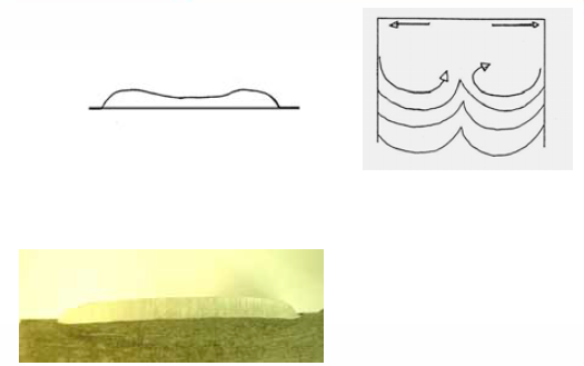
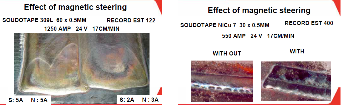
The shape of the solidification ripples should be used to control the intensity of the magnetic field. The criterion for the correct intensity of the magnetic fields is when the solidification lines become symmetrical. FIG 17 is an illustration of the action of the magnetic steering device on the bead profile and on the solidification lines. In most cases the south and north
poles of the magnetic control requires different currents through each of the solenoids.
It is obvious that the intensity on each solenoid has to be adapted to the working conditions on a particular workpiece, taking into account any magnetic blow effect which can not be previous calculated. The standard magnetic steering device is capable of putting five amps on
each solenoids. For cases where the magnetic deflection from the workpiece is intense solenoids with stronger magnetic fields have been used (CED M 1280).


FERRITE DETERMINATION IN CLADDING
The ferrite is non-uniformly distributed in a given weld
Ferritscope :
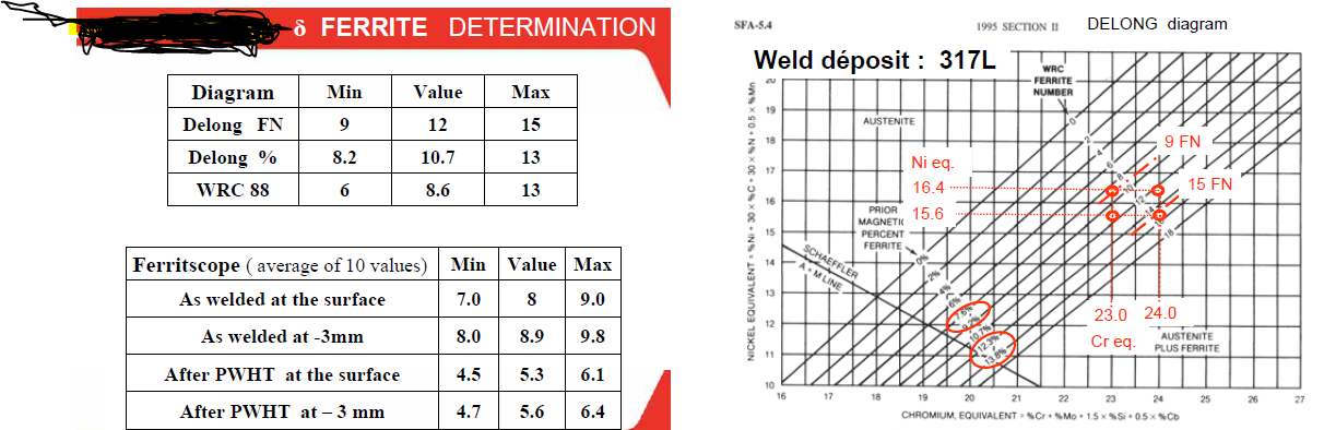
To a first approximation, the magnetic response of an otherwise austenitic weld metal is proportional to the quantity of ferrite present. For a industrial cladding type 317L, an average value of 10 measurements is 8.9 FN, and the standard deviation σ is 1.1. The Confidence interval of 95% on the average value is +/- 0.9 ( from 8.0FN up to 9.8 FN ) , and on the individual value is +/- 2.2 , ( from
6.7FN up to 11.1 FN )
Chemical composition :
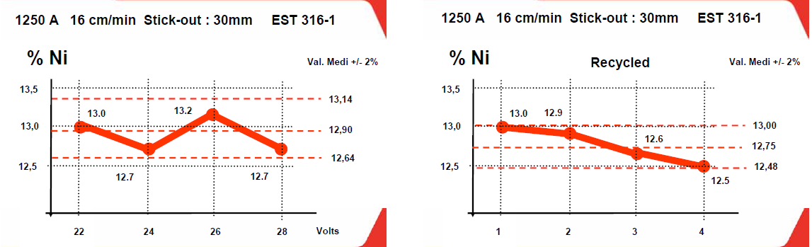
The amount of ferrite depend of the ferrite promoters ( such as chromium) and austenite promoters ( such as NICKEL).
Different diagrams should be used as prediction tools, the most accurate diagram is WRC 1992.
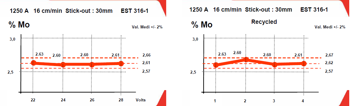
For standard stainless steel, the precision of the chemistry ( by spectro ), for Cr, Ni, Mo, Nb, … : is about +/- 2%, and for the other element like C, N, .. +/- 5%.
Following the AWS, variations in the results of chemical analyses encountered from laboratory to laboratory can have a significant effects on the calculated ferrite value, changing it as much as 4 to 8 FN ( SFA 5.4 A6.10.4 edition 1995)


Welding direction
Setting the magnetic steering

Start with 3.5Amps at the NORTH and 3.0 at the SOUTH Generally, set the NORTH magnet 0.5 to 1 Amp higher than the SOUTH

If you have undercut at one side, you need to increase the current in the magnet of this side, or decrease the current of the magnet at the other side

If the setting is too high, the weld will be too wide and dip in the middle If the setting is too low, the weld will be narrower and will peak in the middle.
Adjustment of strip nozzle
The spool of strip should be positioned to feed into the nozzle without twisting and without excessive braking on the spool holder Without pressure on the drive roll, the strip should run freely though the head Put the pressure on the contact shoe, the strip should still be able to be pushed by hand through the nozzle ( difficult but possible )
Apply the pressure to the feed rolls up to the strip is pushed automatically through the contact tip, , than increase a little bit this pressure.
Cable section
Tension
Always check the tension between the solid copper connector and the ground.
To have 24 Volt on the cladding head, we need some time more than 28 Volt at the power source,
( due to the section and the length of the cables )
If we find more than 0,4V for AS or more than 0,6V for ES between the solid copper ground and the strip, it is necessary to check the quality of the connexions, the pressure on the movable finger, the clearness of the contacts, ( contact shoe and movable finger).

Starting the weld
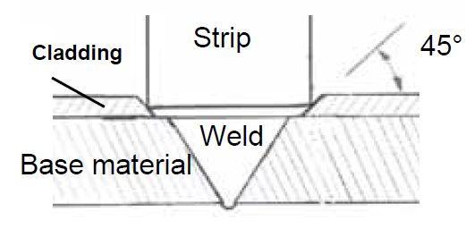
Cut the strip at an angle of 45° for easier starting
It is usually better to start the welding power , in view of melt a small quantities for flux and strip before starting the travel speed.
Stopping the weld.
It is usually better to cut the travel speed, before cutting the welding power.
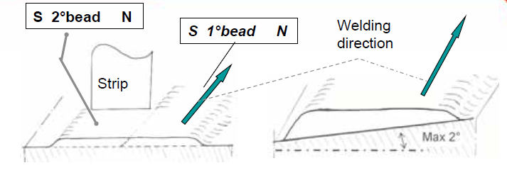
Always clad in a such manner that the NORTH side is onto the SOUTH side.
The surface on which you are working could be flat, if not, the weld will be thicker on the lower side with a steeper edge which could result in a slag entrapment when overlapping ( max incline should be 2° ).

The width of the lane should ideally have been designed to accept a single run of weld with a strip at 90°. If not, it may be necessary to angle the strip as follow
Sometimes , it is necessary to produce a cladding narrower than the strip. This may be produced by using a strip with a angle to reduce the effective width of the bead .The greater the angle of the strip, the narrower the bead width.
To maintain the same dilution and thickness of the deposit, we need to increased the speed ONLY.
The new speed is be calculated as follow . Strip width X original speed


Always clad in a small UP HILL position ( max 2° ) , in this case the weld metal flows back, and the base metal is exposed and the penetration increase, and the risk of lake of fusion decrease.
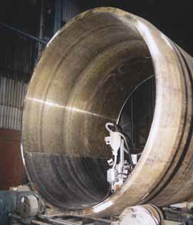
In case of cladding inside a curved surface, like inside a shell, the strip should be in front of the “bottom dead centre” to be in small UP HILL position .
Cut the strip at an angle of 45° for easier starting.
It is usually better to start the welding power , in view of melt a small quantities for flux and strip before starting the travel speed. Stopping the weld.
It is usually better to cut the travel speed, before cutting the welding power.


Always clad in a small UP HILL position ( max 2° ) , in this case the weld metal flows back, and the base metal is exposed and the penetration increase, and the risk of lake of fusion decrease.
In case of cladding inside a curved surface, like inside a shell, the strip should be in front of the “bottom dead centre” to be in small UP HILL position .


Always clad in a such manner that the NORTH side is onto the SOUTH side.
The surface on which you are working could be flat, if not, the weld will be thicker on the lower side with a steeper edge which could result in a slag entrapment when overlapping ( max incline should be 2° )

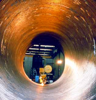
Different Cladding Examples with Pictures
Soudotape NiCrMo 22 Record EST 201 C
Soudotape 625
Record EST 201

SOUDOTAPE 420 Record EST 420
Valves cladded with Soudotape 625 (30*0.5) and Record EST 236
(ESW) and Record NFT 201 (SAW)

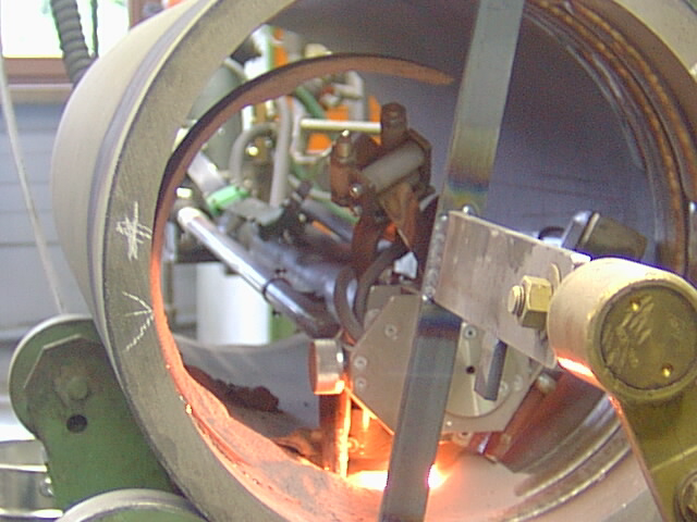
Gas tube plate surfaced with ESW using Soudotape 625 and Record EST 201 cooler

ESW dia 800mmwallthickn 40mm , length 4m)
Using Soudotape 24.12LNb with Record EST 136

Offshore separator vessel (dia 2.5m) using Soudotape NiCu7 (60*05)and Record EST 400.
Tube for process furnace (dia 2.6m, lenght 4.5m, wall thickn 40mm – Cladded with Soudotape NiCrMo 7 (60*0.5) and Record EST 201C (alloy C4)
Vessel bottom overlayed with the ESW process using Soudotape 21.13.3L (60*0.5) and Record EST 122.

ESW surfacing of chemical vessel with 316L using Soudotape 316L and Record EST 316-1

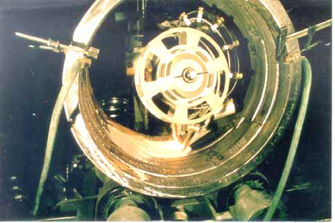
Electroslag strip cladding with Soudotape 625 (30*0.5) and Record EST 236 (pipe dia approx 45 cm)

ESW surfacing of chemical vessel with 316L using Soudotape 316L and Record EST 316-1

Conical carbon crusher overlayed with Soudotape 625 and Record NFT 201

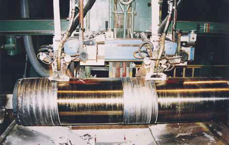
Paper industry roll surfaced with ESW using Soudotape 430 (60*0.5) and Record EST 452 (3 layers – surface hardness 370HB

Reconstitution of Cu Ni 90/10 cladding
One layer
Chemistry of the cladding deposit : Cu : 80 % Ni : 18 % Fe : 2%