This article is about tachometer working principle, intricate design considerations, the explanation of circuitry, and a comprehensive exploration of their applications. Join us in deciphering the language of rotational speed as we delve into the anatomy of tachometers, discovering their significance in diverse industries, and weighing the pros and cons that shape their dynamic presence in the world of engineering.
What is Tachometer?
A tachometer is a device used to measure the speed of rotation of a mechanical system, typically an engine or shaft in a vehicle or machine. It provides a real-time reading of the number of revolutions per minute (RPM) that the system is undergoing. Tachometers are commonly found in vehicles, industrial machinery, and other mechanical systems where monitoring and optimizing rotation speed are important for efficient and safe operation.
What is Tachometer Working Principle?
A tachometer operates on the fundamental principle of measuring the rotational speed of an engine or shaft, and its working mechanism involves a series of key steps. First and foremost, the tachometer incorporates a sensor that detects the rotational motion of the shaft. This sensor utilizes various technologies, such as magnetic, optical, or mechanical principles, to identify specific features on the rotating shaft.
As the shaft undergoes rotation, the sensor generates electrical pulses. The frequency or rate of these pulses directly correlates with the speed of rotation. Each pulse represents a specific increment of rotation, forming the basis for calculating the rotational speed.
The generated pulses are then subjected to signal processing within the tachometer’s circuitry. This processing phase involves amplifying and conditioning the signal to make it suitable for further analysis. The goal is to refine the signal, ensuring that it accurately reflects the rotational dynamics of the shaft.
Following signal processing, the next crucial step involves converting the processed signal into a standard unit of measurement for rotational speed—revolutions per minute (RPM). This conversion is typically carried out using electronic components like microcontrollers or digital signal processors, which play a pivotal role in translating the pulse frequency into RPM.
Finally, the tachometer displays the calculated RPM on its output. This display can take various forms, including an analog dial with a needle indicating the speed or a digital readout presenting the numerical value. In essence, the tachometer’s working principle revolves around the seamless translation of mechanical rotation into an electrical signal, subsequent processing of that signal to derive speed information, and the final presentation of the speed in a readable format. The specific implementation may vary based on the type of tachometer and the technology employed to meet the specific requirements of different applications.
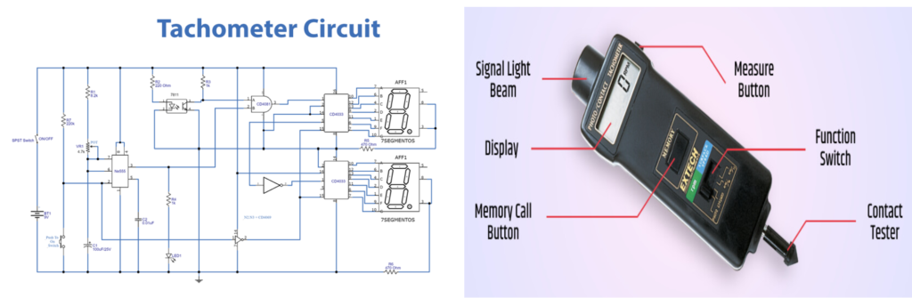
Tachometer Circuit Explanation
The primary objective of our article is to devise an efficient system for measuring and displaying the rotational speed of a shaft. Embracing a straightforward approach, we aim to achieve this by implementing a method centered around counting the number of shaft rotations within a specified time frame. The essence of our system lies in establishing a direct proportionality between the resulting count and the actual speed of the shaft. This simplicity in approach not only facilitates ease of implementation but also promises accuracy in gauging the rotational dynamics of the targeted machinery.
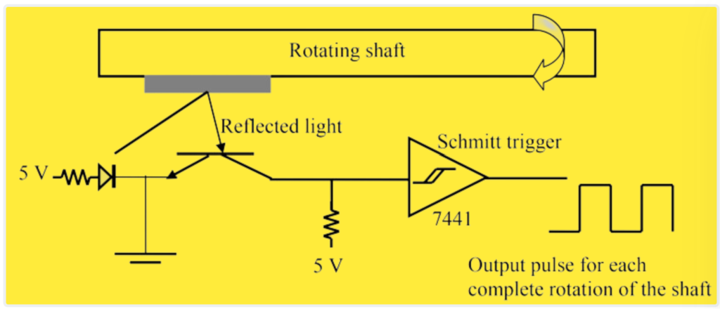
Sensor
The detection of shaft rotation in a tachometer system relies on various sensors, and one effective option is a proximity sensor. These sensors utilize magnetic, optical, or mechanical principles to identify specific features on the rotating shaft. For instance, an optical sensor employing an LED-phototransistor pair can be utilized in the tachometer system. This involves placing a small piece of reflective tape on the shaft, which, as the shaft rotates, reflects light to the optical sensor. The interruptions or variations in the reflected light pattern are then translated into electrical signals, enabling the system to accurately detect and measure the rotational speed of the shaft. This optical sensor approach offers precision and reliability in capturing the rotational dynamics of the machinery.
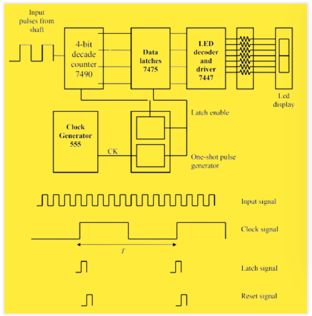
Counter
To implement the counting and display of pulses over a specified time interval T in our tachometer system, we integrate a circuit featuring a decade counter, a 555 oscillator circuit, and additional cascaded 7490 counters when the count exceeds nine within the period T. The 555 oscillator circuit, utilizing a resistor-capacitor combination, determines the time period T for counting pulses.
The decade counter is responsible for counting the pulses, and it is reset by a negative edge on the R signal after the time period T elapses. If the pulse count surpasses nine within T, additional 7490 counters are cascaded to extend the counting range. Before the counter reset, the output is stored by 7475 data latches, which are enabled by a brief pulse.
This intricate circuitry ensures that the system accurately counts pulses within the designated time frame, storing the count before resetting, and allowing for the extension of the counting range when needed. The pulse count, when displayed, correlates directly with the shaft speed in revolutions per minute, providing a real-time and precise indication of the rotational dynamics of the machinery.
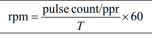
Where ppr is the number of pulses per revolution generated by the sensor.
Decade Counter
The decade counter plays a pivotal role in our tachometer system, functioning as a negative edge-triggered counter. Operating on a binary coded decimal (BCD) format with 4 bits, it is specifically designed for applications that involve decimal counting. The output sequence of the 4 bits, as the counter increments from 0 to 9, follows a predetermined pattern.
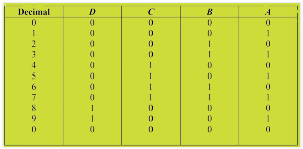
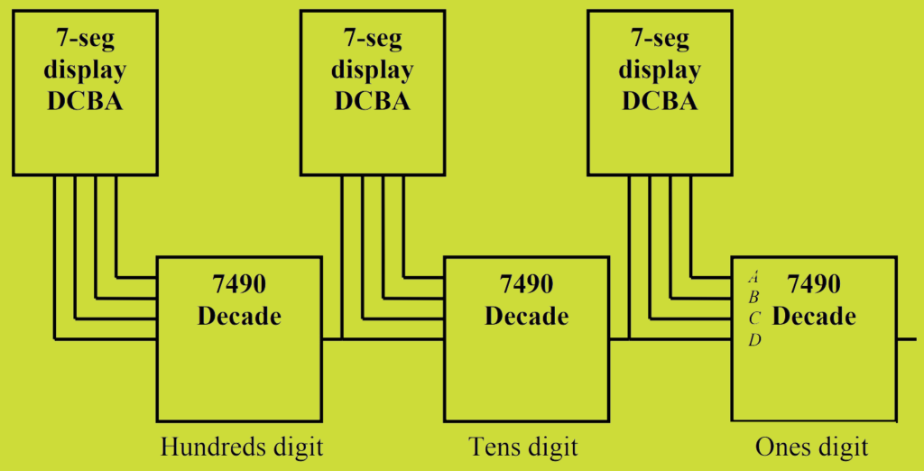
For applications requiring counting in powers of 10, BCD counters like this one can be seamlessly cascaded. For instance, Output D from the first 7490 can serve as the clock input for a second 7490, effectively linking the two counters. This cascading arrangement allows for an extended counting range, enabling the system to accurately count from 0 to 99 and beyond. This modular and scalable design is a key feature, enhancing the versatility and adaptability of our tachometer circuit.
Schmitt Trigger
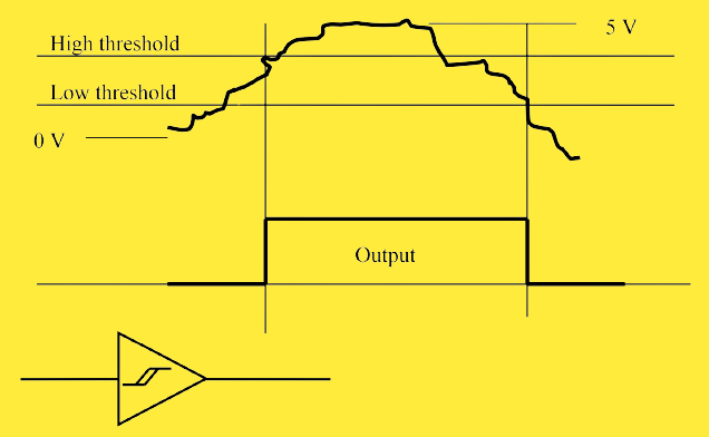
In our tachometer circuit, we encounter scenarios where digital pulses may lack sharp edges, exhibiting a gradual transition from 0 to 5 V over a finite time period. Moreover, these signals may be subject to noise, resulting in an erratic or jumpy behavior. To address this, we introduce the Schmitt trigger, a crucial component capable of transforming such signals into sharp pulses with the added benefit of threshold hysteresis.
The Schmitt trigger achieves this by incorporating a hysteresis mechanism, establishing distinct upper and lower voltage thresholds for signal transitions. This hysteresis ensures that the signal must cross a higher threshold to switch from low to high and a lower threshold to switch from high to low. As a result, the Schmitt trigger effectively filters out noise and produces clear, well-defined pulses. This feature enhances the robustness of our tachometer system, ensuring reliable signal processing even in the presence of varying signal qualities.
555 Timer
The versatile 555 integrated circuit, often referred to as the “time machine,” showcases a remarkable blend of digital and analog functionalities, making it a go-to component for an array of timing tasks. Its applications span across bounce-free switches, cascaded timers, frequency dividers, voltage-controlled oscillators, pulse generators, LED flashers, and more.
One particularly useful circuit achievable with the 555 IC is the monostable multivibrator. This configuration involves adding an external capacitor and resistor to the 555 circuit. Known as a one-shot, this circuit generates a single pulse of a specified duration upon receiving a trigger signal. The length of the pulse is determined by the time constant of the resistor-capacitor combination.
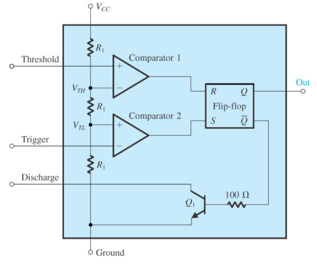
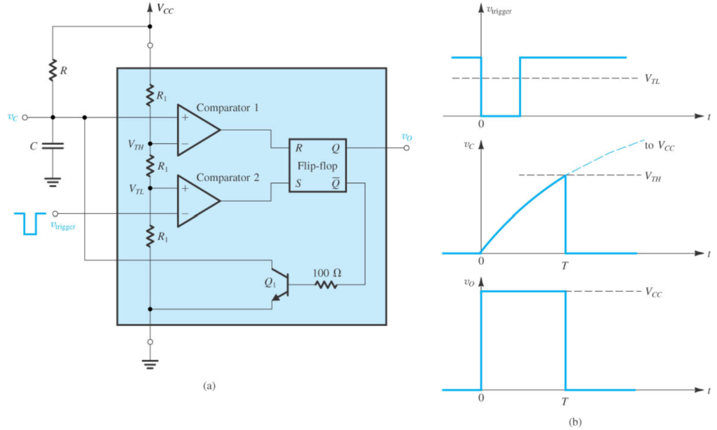
Breaking down its internal components, the 555 circuit comprises two comparators that drive an RS flip-flop, an output buffer, and a transistor responsible for discharging an external timing capacitor. The threshold comparator, labeled as Comparator 1, converts its input with an internal voltage reference set at 2/3 Vcc. Meanwhile, Comparator 2, named the trigger comparator, compares the input trigger voltage to an internal reference set at 1/3 Vcc. This intricate arrangement enables precise and customizable timing functions, making the 555 IC an invaluable tool in the world of electronic circuitry.
Operation
The operation of the 555 timer, also known as a one-shot, involves a systematic process driven by external components. Here’s a step-by-step breakdown of its operation:
- Charging the Timing Capacitor:
- The one-shot is initiated by triggering it, causing a current set by an external resistance to charge a timing capacitor. This charging process is a crucial step in determining the timing interval.
- Single Cycle During Timing Interval:
- Once triggered, the charging network cycles only once during the timing interval. This interval includes the recovery time necessary for the capacitor to charge up to the threshold level.
- Initial State – Vcc High:
- When a high voltage (Vcc) is applied to the trigger input, the trigger comparator output is low. This results in the flip-flop output being high, activating the transistor, and discharging the timing capacitor to ground potential. Consequently, the output of the 555 circuit is low.
- Trigger Input Transition – Vcc Low:
- Upon applying a negative voltage to the trigger input, the output of the trigger comparator goes high. As the trigger pulse drops below 1/3 Vcc, the output of the flip-flop goes low. This change in state causes the output of the 555 circuit to go high, turning off the transistor.
In summary, the 555 timer, functioning as a one-shot, operates by charging a timing capacitor with a current determined by external resistance. Triggering initiates a single charging cycle during the timing interval. The state changes based on the application of Vcc to the trigger input, allowing for precise control of the timing functions in various electronic circuits.
FAQs:
What is a tachometer used for?
What are the meanings of tachometer?
How do you check RPM on a tachometer?
Prepare the Tachometer:
Ensure that the contact tachometer is in good working condition and properly calibrated. If necessary, refer to the manufacturer’s instructions for calibration procedures.
Select the Measurement Mode:
Set the tachometer to the appropriate measurement mode for RPM. Most contact tachometers have a specific setting for RPM measurements.
Prepare the Rotating Object:
Make sure the object whose RPM you want to measure is accessible and safe to touch. If it’s a rotating shaft, ensure that it’s not in a hazardous condition.
Position the Tachometer:
Bring the tip of the tachometer’s sensor into contact with the rotating surface of the object. Ensure that the sensor is making good contact for accurate readings.
Stabilize the Reading:
Allow the tachometer a moment to stabilize and provide a consistent reading. The tachometer may need a short time to capture and display the rotational speed accurately.
Read the Display:
Once the tachometer stabilizes, read the displayed RPM value. Some tachometers may have a digital display, while others may use an analog dial with a needle indicating the RPM.
For measuring linear surface speed, if applicable:
Attach the Wheel:
If the tachometer has a wheel attachment for measuring linear speed, connect it to the sensor tip.
Touch the Moving Belt or Surface:
Bring the wheel attachment into contact with the moving belt or surface whose speed you want to measure.
Read the Display:
Similar to measuring RPM, allow the tachometer to stabilize and then read the displayed linear speed value.
Always prioritize safety when using a contact tachometer, especially when dealing with rotating machinery. Ensure that you follow safety guidelines and use appropriate protective gear if needed.