In the realm of fluid transportation through piping systems, managing the effects of thermal expansion is paramount. As liquids change temperature within a closed system, their volume can fluctuate, potentially leading to structural stress or even system failure. To mitigate these risks, the Saudi Aramco Engineering Standards (SAES) have established a comprehensive set of guidelines under SAES-L-140. This article delves into the minimum mandatory requirements outlined in this standard, ensuring the safe relief of thermal expansion in piping systems, with a focus on scenarios where liquid flow is obstructed.
To read and download full document of SAES-L-140.
SAES-L-140Understanding Thermal Expansion
When liquids are transported through pipelines, their temperature can rise due to various factors, including environmental conditions or the nature of the fluid itself. As temperatures increase, the liquid tends to expand, potentially causing an increase in pressure within the piping system. Without appropriate measures, this pressure buildup can lead to structural issues, leakage, or even catastrophic failures.
The Role of SAES-L-140
SAES-L-140 is a foundational standard that addresses the critical issue of thermal expansion in piping systems. It sets forth mandatory requirements for ensuring the safe and efficient relief of thermal expansion-induced pressure when the flow of liquid is blocked within the piping. It’s important to note that this standard specifically excludes considerations related to thermal expansion caused by fire.
Relief Requirements
In the piping systems, it’s crucial to manage the effects of thermal expansion, especially when dealing with liquids. When liquids change temperature inside a closed pipe, they can expand, potentially causing excessive pressure that may lead to structural issues. To mitigate these risks, we follow guidelines outlined in the thermal expansion relief standard, often referred to as SAES-L-140. This article will break down these requirements, focusing on situations where liquid flow gets blocked.
Imagine a pipeline transporting liquid. When the temperature of that liquid changes, it can expand or contract. If the flow is obstructed, say by closing a valve, this change in temperature can cause an increase in pressure within the pipeline. This pressure buildup could potentially damage the piping system or even lead to a catastrophic failure.
SAES-L-140 is a crucial standard that helps us address thermal expansion in piping systems effectively. It lays out mandatory requirements for ensuring that excess pressure resulting from thermal expansion, when liquid flow is blocked, is safely relieved. It’s important to note that this standard doesn’t cover scenarios where thermal expansion is caused by fire.
Technical Requirements (Thermal Expansion Relief)
- Installing Relief Valves: The standard mandates the installation of relief valves in piping systems when there’s a possibility of thermal expansion. These valves act as safety mechanisms to release excess pressure.
- Choosing the Right Valves: Engineers and operators must carefully select relief valves suitable for the specific conditions of the piping system. This includes valve sizing and setting, ensuring they can effectively manage pressure relief.
- Pressure Release Rates: SAES-L-140 specifies the required pressure release rates that relief valves must achieve. These rates are determined based on factors like the liquid’s properties and the piping system’s operating conditions.
- Regular Testing and Maintenance: The standard emphasizes the importance of routinely testing and maintaining relief valves. Ensuring these components are in optimal working condition is vital for the piping system’s continued safe operation.
- Documentation: Detailed records about relief mechanisms, their settings, and testing results must be maintained. This documentation serves as a crucial reference for operators and maintenance personnel.
- Exclusions: While SAES-L-140 addresses most scenarios, it explicitly excludes considerations related to thermal expansion caused by fire. Different standards and guidelines are in place for those specific situations.
- The temperature of insulated lines with steam tracing or other external heat source shall be assumed to reach the temperature of the source.
- The temperature of a liquid in piping connected to the cold side of a heat exchanger shall be assumed to reach the temperature of the hotter medium of the exchanger.
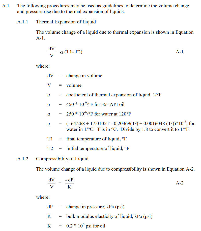
- The following parameters that affect the pressure rise in a pipe due to solar radiation shall be considered as minimum:
- a. Thermal expansion of liquid.
- b. Compressibility of liquid.
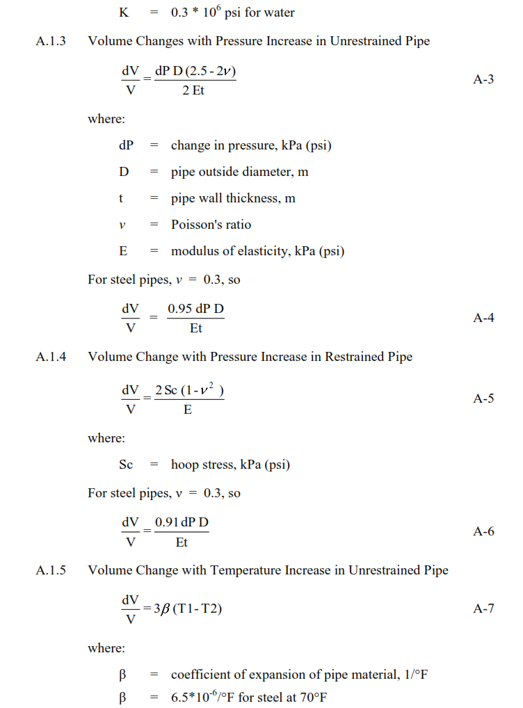
- c. Pipe expansion due to pressure.
- d. Thermal expansion of pipe.
Ensuring Safety and Efficiency
By adhering to SAES-L-140’s requirements, organizations can guarantee the safety and efficiency of their piping systems, particularly when dealing with thermal expansion. Preventing excessive pressure buildup due to temperature changes is not just about protecting the system but also the people and the environment around it.
Relief Valve Installation Requirements:
6.1: When installing a thermal relief valve, make sure its pressure setting doesn’t go above 110% of the highest pressure the system can handle when it’s really hot and not operating. This should consider things like how the pipes are stressed, all the forces acting on them, and the strength of the weakest part of the system.
6.2: Choose the relief valve based on the guidelines in SAES-J-600.
6.3: For pipelines that stretch across long distances, place the relief valve where it provides the most safety above the normal operating pressure. This should take into account the height differences in the pipeline and how the liquid flows unless there are specific accessibility requirements. If the relief valve isn’t in a protected area, cover it to prevent people from tampering with it or causing damage. You can follow Standard Drawing AA-036873 for guidance on this.
6.4: If the thermal relief valve releases dangerous gases inside an industrial area, connect its outlet to a closed pipe system. If it’s releasing liquids like oil, you can direct them to a point where they can enter the sewer naturally due to gravity.
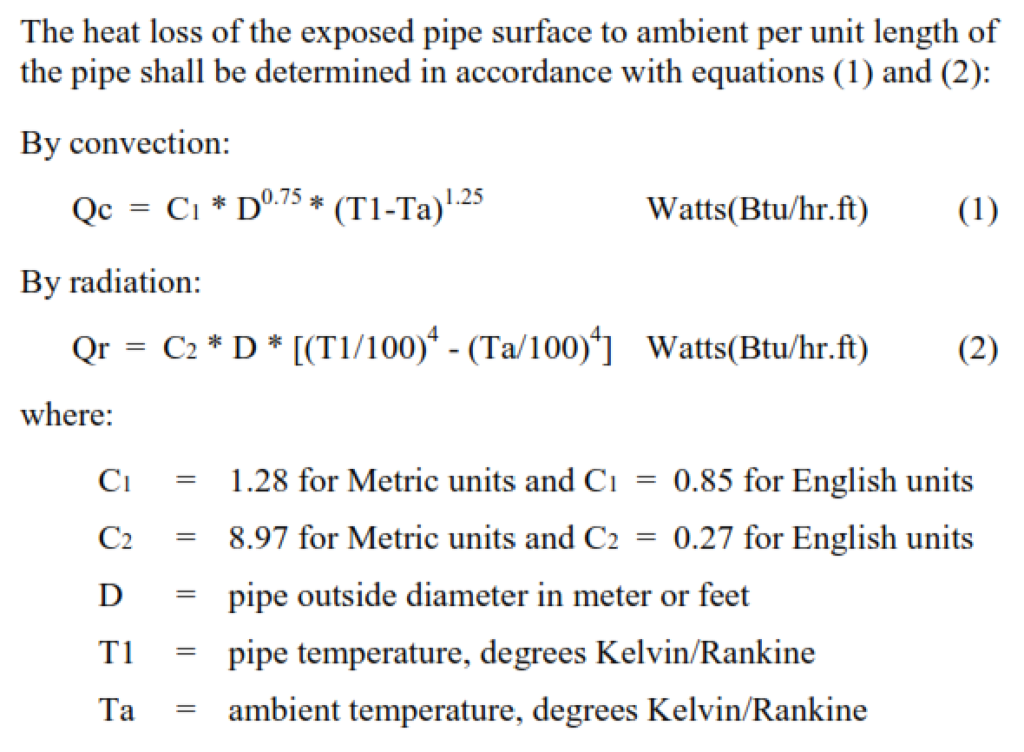
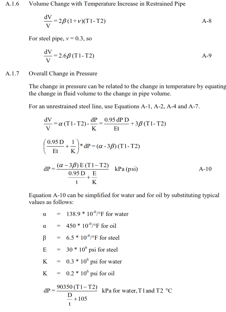
Calculation Method for Thermal Relief

International Codes and Standards
American Petroleum Institute
API MPM CH11.1 – Manual of Petroleum Measurement Standards:
Physical Properties Data – Section 1: Temperature and Pressure Volume Correction Factors for Generalized Crude Oils, Refined Products and Lubricating Oils.
API MPM CH11.2.2 – Manual of Petroleum Measurement Standards: Compressibility factors for Hydrocarbons (0.350-0.637 Relative Density and -50°F to 140°F Metering Temperatures).