This article is about to guide the responsible persons in conducting Transformer Differential Protection stability & sensitivity test as per procedures.
Testing the stability and sensitivity of transformer differential protection is crucial to ensure the reliable operation of transformers and to prevent unnecessary tripping or failure to operate during fault conditions. Here’s a detailed procedure for conducting stability and sensitivity tests for transformer differential protection:
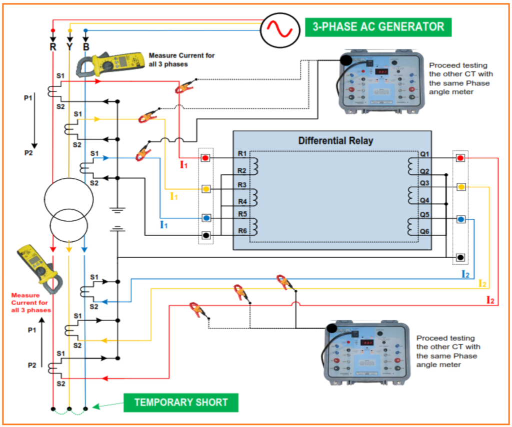
Test Equipment: 3 phase AC Generator kit, Clamp Meter and Phase Angle Meter.
Safety Precautions: The following Safety precautions shall be taken in consideration prior, during and after conducting the test measurements.
- Safety tagging shall be implemented.
- Isolate the Area by Safety Warning Tape.
- Keep a Safe Distance from the device being tested.
- Wear Appropriate Personal Protective Equipment(PPE) Prior to starting any testing activity.
- Implementation of Proper Grounding.

ADDITIONAL SAFETY PRECAUTIONS:
1.) LOCKOUT RELAY should be isolated and ensure NO POSSIBLE tripping during the test
2.) Check that any high impedance protection (ex. Transformer REF protection) is shorted before primary injection on their CT Cores.
3.) Any CT cores not related to Transformer protection should be shorted for safety.
4.) Check that Transformer is short-circuited at the LV side after the transformer LV Side CT for differential protection.
5.) Isolate the Differential Protection Trip Links.
6.) The injected current should not exceed the smallest turns ratio CT.
7.) Check the balance and phase sequence of the three phases power supply at the HV side of the transformer.
Transformer Differential Protection Stability & Sensitivity Test
- Perform General Visual Inspection.
- CT loop and primary injection tests should be completed for High voltage and Low voltage sides.
- Make sure there is no more than one earthing point on the CT at the secondary circuit for HV side and LV sides.
- The final settings must be applied and tested before the stability test.
- Check that all associated CT cores are having the same Knee point nearly for high voltage side and low voltage sides for high impedance protection.
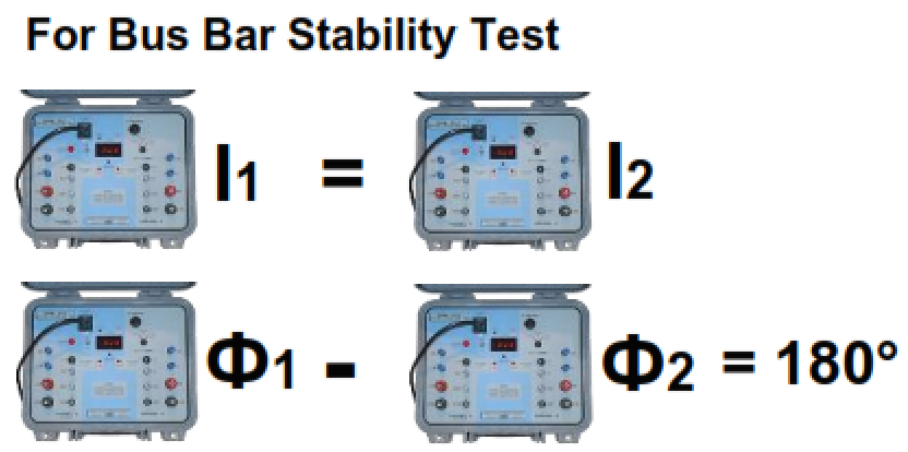
- For Transformer Differential Stability Test for 3 Phases, Use first tap, middle tap & last tap.
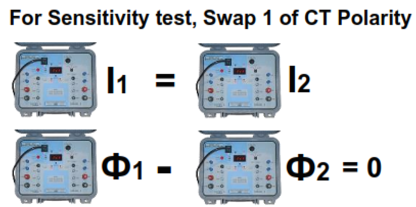
- For Transformer Differential Sensitivity Test Swap 3 phase of CT Polarity. Use middle tap only.
- Normalize the reversed CT.
- Normalize the trip isolation links.
- Normalize the shorted CT cores.
Test Results and Acceptance Values.
The results of testing the Transformer Stability should match what is expected as per the design and implementation of the Transformer Scheme.