Main tests are Transformer testing, transformer oil testing, transformer winding, current transformer, Transformer Ratio test.
TRANSFORMER TESTING ON SITE
After a transformer has been completely assembled on site, it must be tested to confirm successful shipment and correct assembly. All tests must be carried out with instruments that have traceable, valid calibration. These instructions are intended to provide guidelines in the test of transformers to maintain their quality and reliability.
They are intended for the guidance of personnel who have been trained for, or who have experience in test of high-voltage electrical power equipment, including the use of good safety practices. These instructions are intended to supplement, and not eliminate the necessity for such training.
The Transformer testing results are to be recorded on a Test Record. The second sheet of this Transformer testing Record is a list of all possible tests, some of which may not be applicable. When the on-site project manager or the assembly supervision has marked all applicable tests, this sheet forms an order-bound directive for the tests to be carried out.
Main tests are Transformer testing, transformer oil testing, transformer winding, current transformer,Transformer Ratio test.
Transformer Ratio test
The Transformer Ratio test is used to confirm that the winding turns ratio is consistent with the voltage ratio as shown on the Nameplate.
Transformer Ratio test
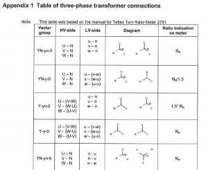
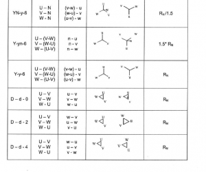
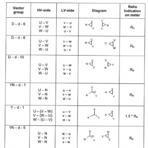
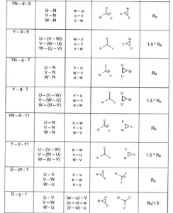
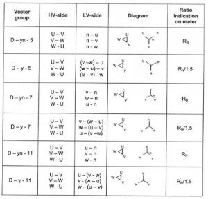
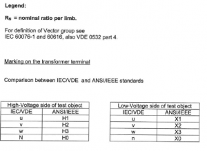
This is done primarily to check for shipping damage and to confirm that any tap-changer leads installed in the field have been correctly connected. In addition to the ratio measurement, exciting current is also often measured. The ratio measurements is normally done with a ratio bridge. Table of three-phase transformer connections Appendix 1. Transformer Ratio test
Transformer Winding resistance test
Measure the resistance of each winding at the rated and extreme tap positions and compare the results to the original value in the Factory test report. If the Tap Changer connections have been made at site, measuring at all positions should be done. Transformer winding Resistance is dependent on the temperature of the winding. The mean temperature of the oil is representative of the winding temperature, and providing that the oil is at a uniform temperature, the top oil temperature gauge value can be used. Resistance comparison must always be made at a common temperature. The conversion formula for copper and aluminium transformer winding is show below. The formula giving the relation between the resistance and the temperature is:
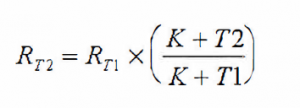
where RT2 = Resistance of the winding at temperature T2
RT1 = Resistance of the winding at temperature T1
K = 234.5 for winding made of copper ace to IEEE,
K = 235 for winding made of copper ace IEC
K = 225.0 for winding made of aluminium
The time constant may be very long when low voltage and low current sources are used.
Note:
A high voltage surge occurs at interruption of DC current at end of measurements. A discharge circuit should be used. Eg. see IEEE Std 62 figure 2.
Main tests are Transformer testing, transformer oil testing, transformer winding, current transformer, Transformer Ratio test.
Transformer Check of vector group
The purpose of this series of tests is to check the polarity and the phase relationship of the multiple windings in a transformer. The test is carried out simultaneously with the transformer turns ratio test when using a turns ratio test set. In order to define the connection of a three-phase transformer and to facilitate the parallel connection with other transformers, the international standards prescribe specific vector groups. Every country has its own designation for the vector groups. IEC and IEEE (in USA) have recommended a method that will result in standardized and fully defined designations.
Transformer Insulation resistance test
Insulation resistance can give some information of the integrity of the insulation structure. As an insulation structure begins to deteriorate due to contamination and moisture, the insulation resistance will decrease. The test equipment used is a DC insulation tester (Megger). It is essential that it is of a type, which is suitable for measurement on transformers and transformer core insulation. Ensure that bushings are clean and dry. Insulation resistance is temperature dependence why it is important that the oil temperature is noted.
After the test has been completed, all terminals shall be grounded time enough to allow any trapped charge to decay to negligible value.
Transformer main windings
When conducting an insulation resistance test on transformer windings, a 2.5 or a 5 kV megger can be used. Test every winding to ground and between each winding. Make sure that the bushing porcelains are cleaned since dirt deteriorates the insulation resistance. The transformer tank must be grounded during the test. If the insulation resistance is 1 Mn/kV system voltage for the winding, it is acceptable. If lower values are measured, this must be reported to an ABB representative.
According to IEEE the following shall be measured. High voltage to low voltage and ground, low voltage to high voltage and ground.
Current transformers
When insulation resistance testing a current transformer, a 500 or 1000 megger is used. Test every connection to the ground. The acceptable value is 10 Mn.
Control circuit cabling and auxiliary power cabling
When insulation resistance testing control circuit cables and supply cables, a 500 or 1000 V megger is used. The acceptable value is 10 Mn. Test every connection to the ground.
Core to tank/core clamp
When insulation-testing a transformer core a 1000 V megger is used. The testing time is 1 minute. Core to ground, core-clamp to ground and core to core-clamp shall be measured.
Capacitance and power factor or dissipation factor measurements
This is optional test in accordance with IEC See Clause 10.10 of IEEE C57.12.90-1999.
Check of tank ground circuit continuity
By means of a buzzer check the ground connection between the tank and turret(s), and between the tank and bushing
flanges.
Polarity check of current transformers
In order to make sure that the current transformer is in its correct position in relation to the bushing (conductor), a polarity check must be carried out. By checking the polarity in this manner we are also certain that the current transformer generates a secondary current. The ratio test and the magnetizing curve are not performed on site in conjunction with the transformer assembly. Polarity check of current transformers.
In order to make sure that the current transformer is in its correct position in relation to the bushing (conductor), a polarity check must be carried out. By checking the polarity in this manner we are also certain that the current transformer generates a secondary current. The ratio test and the magnetizing curve are not performed on site in conjunction with the transformer assembly.
Check of thermometers and thermostats
Oil and temperature gauges must be tested with their associated control, alarm and trip circuitry. Register the test records and compare them with the set points on the circuit diagram. Perform functionality tests to confirm operation of the alarm/trip contacts.
For analogue thermometers
Open the both of the connections of the current transformer feeding the heating resistor of the winding temperature indicator, and measure the total heating resistance. Record the value in the test record and compare the result with the resistance in the Factory test report of the transformer.
For digital thermometers:
Check that the settings for winding temperature gradients and hot spot factor agrees with the values given in the factory test reports.
Main tests are Transformer testing, transformer oil testing, transformer winding, current transformer, Transformer Ratio test.
Transformer Oil tests
Check of the oil level
Check the oil level in:
– The transformer
– The tap-changer
– Any other separate compartments
Check that all devices containing oil that must be completely filled have been purged of air.
Transformer Check of dielectric strength values
The transformer’s performance and longevity greatly depends on the quality of the oil that is used. Therefore the oil’s dielectric strength is checked before the transformer is handed over.
A sample is taken from the conservator and the transformer/reactor’s bottom valve and in some cases even from separate coolers, etc. a Since the value of the dielectric strength greatly depends on which type of electrodes being used, it is essential to record the information in the test report. The acceptable dielectric strength value is indicated in 1ZBA4601-213
Power factor checking of transformer
The power factor is a measure of the dielectric losses in the oil when used in an alternating electric field and of the energy dissipated as heat. A low power factor indicates low a-c dielectric losses. It can be useful as a means to see changes in quality resulting from contamination and deterioration in service or as a result of handling. The test should be made as per IEC 247 or ASTM D 924.
For new oil that has never been in contact with the transformer, the power factor at 90°C or 100°c and 50 or 60 Hz shall not exceed 0.005. (0.5%)
lnterfacial tension checking of transformer (Optional)
This test has shown by practice to give a reliable indication of the presence of hydrophilic compounds.
The test should be made as per ISO 6295 or ASTM D 971.
For new oil that has never been in contact with the transformer the interfacial tension against water shall be > 40 mN/m at 25 °C.
Sampling of oil for dissolved gas analysis by special request
Sometimes customers require that an oil sample for a gas analyse shall be taken. There are special instructions regarding this test within the ABB group. If the analysis is conducted at another laboratory, other vessels and methods might be prescribed.
Operational test of supervisory equipment
Transformers and reactors are provided with special equipment for supervision of operation, overloading, cooling and many other purposes. After installation has been completed and before the transformer or reactor is placed in service, all the accessory equipment is tested preferably in conjunction with the equipment with which it will be used in service. Individual testing is conducted using a buzzer that is connected to the appropriate terminals in the control cabinet. Prior to energizing, the Customer is obliged to perform complete commissioning tests, which include the functions of the entire system, to which the transformer is an integral part.
Operational test of other equipment
Before the transformer is place in service, the rotation direction of the pumps and fans of the cooling equipment are checked. Furthermore, the tripping of the motor protection devices are checked as well as the signal that is activated for each tripped motor protection device.
The rotation direction of the pump is checked according to the following:
When the pump is filled with oil and has the correct rotation direction, only a slight purring sound is heard. If the pump wheel rotates in the wrong direction, a rattling sound will occur that is several times louder. If uncertainty prevails, shift the two phases on the motor so that it will run in the opposite direction. It will then be easy to determine which rotation direction is correct. Note that if the pump housing is only partially filled with oil, a rattling sound will also occur.
The rotation direction of the fans is checked visually.
The thermal over current protection relays of the fan motors are set according to the rated current that is stamped on the rating plate. The relays for the pump motors are set according to what is stated on the list of apparatus. The thermal over current protection relays of the motors are tripped by a 2-phase connection of each motor.
The signal of the tripped motor protection device is checked by means of a buzzer to the appropriate terminals in the control cabinet.
Verify that shipping plugs, if applicable, have been removed from the motors.
De-energized tap-changer with driving mechanism
At the end of the assembly and before being put into service, the de-energized tap-changer and the drive mechanism are checked.
Operate the tap-changer to its end positions. Then check the drive mechanism’s locking device. Check that the contacts on the drive mechanism and its interlocking device connect and disconnect before the lock in the locking device is completely released.
On-load tap-changer with motor-drive mechanism
If the transformer is fitted with an on-load tap-changer, then the tap-changer and the motor drive mechanism are tested before the transformer is put into service.
The following checks should be done:
All the external shafts have been lubricated
The local/remote control is functioning correctly
The heater in the drive mechanism is working
The pressure relay operates adequately to the pressure setting
The motor protection is adjusted to the current that is stated on the motor’s rating plate.
The drive mechanism indicates the same position as the tap-changer.
The drive mechanism has been operated through all positions manually (with the hand crank) and electrically in ascending and descending positions.
The mechanical stops at extreme positions are working properly
The interlocking switch for the mounted hand crank is working properly
For the details on how to perform the above tests, refer to the appropriate tap-changer product information in the instruction manual.
Final air bleeding
After all the tests have been carried out, the transformer and every separate compartment, including radiator banks, etc., is purged of air through the appropriate bleeding valves.
Main tests are Transformer testing, transformer oil testing, transformer winding, current transformer,Transformer Ratio test.
