The following article is about earthing system, earth electrode, earth rod and the most asked question what is earth or grounding. Here in this article will be describe about also Underground Grounding Installation, Above Grounding Installation, equipment grounding, Grounding Bus Bar Installation and how to do substation grounding.
Required Tools and Equipment for grounding
– Hydraulic Crimping Tool
– Thermite Weld & Accessories
– Cable Cutter
– Forklift
– Bobcat
– Skid Loader
– Stakebed Truck
– Bore hole drilling machine
– Ladders & Scaffolds
– Cable Stripper
– Splicing Knife
– Electrical Pliers
– Ground Tester
– Cadweld Powder (Weld Metal)
– Exothermic Mold
– Mold Holder
– File diff. size
– Cable Cleaning Wire Brush
– Mould Cleaner
– Flint Gun
– Ground Earth rod Clamp
– Grounding Pit
– Ground Earth rod Coupling & Driving Stud
– U-Bolt Ground Clamp
– Other Relevant Tools
What is Earth or Grounding
In electrical, electronics and instrumentation engineering, earth is use for reference point to measure the voltages and it is also return path of current. It is directly or physically connected with the earth. Its main use for safety and other reason also.
Grounding / Earth
- Install earthing system cables, earth rods and accessories as depicted on IFC drawings. Install products in accordance with manufacturer’s instruction, approved drawings and Job Specifications, including Saudi Aramco Electrical Installation drawings.
- Excavation and backfill shall be carried out in accordance with international standard.
- Verify that final backfill and compaction has been completed before driving any earth rod earth electrodes into the ground.
- Install grounding / earth earth electrodes at locations indicated on IFC drawings and job specifications. Ground wells shall be installed and equipped with removable covers for maintenance access to the ground rods and their mechanical connections.
- All surfaces for grounding connections shall be thoroughly cleaned before the connections are made.
- Grounding termination/ connection shall be providing shrinkable sleeve.
- On the steel plate grounding provision an anti-corrosion paint shall be applied after the terminal lugs connection.
- For the grounding loop interconnection with the other package beyond the battery limit, shall have a clear agreement whose will be the in-charged on the connection.
- Following completion of installation, submit “Request for Inspection” (RFI) to site QC Section, indicating scheduled time / date for inspection.
To understand “what is earth” see the topic above.
Underground Grounding Installation
- Check and confirm the actual underground grounding routing for installation against approved construction drawings.
- Layout the grounding grid cable trench by marking using white pulverized powder the areas to be excavated.
- Excavation work shall be in accordance with international standard.
- Excavation shall be performed as required by the design drawings, to the dimensions, grades, and elevation as noted and required.
- All buried grounding conductor shall be installed at a minimum of 460 mm below grade.
- Underground grounding cable connection shall be performed using exothermic connection.
- Ground cables crossing access way shall be run in duct banks or PVC conduits.
- Buried grounding cables shall have clearance of 300 mm (minimum) from any underground obstruction.
- Where there are earth connections between feeders & branches are located in the cable trench, ensure that joints have been connected and tapped before back filling.
To understand “what is earth” see the topic above.
Above Grounding Installation
- Check and confirm the aboveground grounding routing for installation against approved construction drawings.
- All Earthing system points to be checked as per the drawing.
- Earth wire leaving the ground (stub-up) shall be protected by PVC conduits or RGS conduit.
- Sealing for stub-up PVC conduit or RGS conduit.
- The end(s) of ducts and conduit terminating below or in open air shall be sealed with duct sealing putty or an equivalent compound.
- All above ground cable connections shall be compression type.
- All cable Trays are to be bonded together and to the main ground grid with a 70 mm2 green PVC insulated copper ground conductor at interval not exceeding 25 meters apart.
- Frames of Medium Voltage motors shall have at least two (2) ground connections.
- Ensure a complete As-Built record of grounding installation is maintained for above and below ground (Red line/ Mark-Up).
To understand “what is earth” see the topic above.
Grounding Earth rod Installation
- Ground Earth rod shall have the following characteristic:
- Bare copper or copper jacketed steel or galvanized steel.
- Have a minimum length of 2.4 meters. Jointed rods are permitted but each joint must be at least 2.4-meter long.
- For copper or copper jacketed steel rods be minimum of 16 mm in diameter and for galvanized steel rods be a minimum of 19 mm diameter.
- Install the grounding earth rod and accessories as depicted on the IFC drawing.
- Excavation and backfill shall be carried out in accordance with international standard.
- Verify the final backfill and compaction has been completed before driving the ground rod.
- Having confirm the soil final backfill and compaction, install the ground earth rod by driving using a light hammer, or mechanical, pneumatic or gasoline powered ground earth rod drivers.
- Continue driving until the desired depth is obtained.
- Below ground connection to the grounding grid or ground earth rod or between conductors and or grounding rods shall be made using one of the following methods:
- By thermite welding or brazing
- By approved compression grounding connectors.
- For connection at ground test station only where it is necessary to disconnect ground conductors for tests, approved mechanical connectors may be used.
- When using Thermite weld/ Cadweld, the following step shall be performed:
- Prior to making a connection, the detailed instruction and safety precautions provided by the manufacturer should be read properly.
- Sub-contractor will conduct training for skilled manpower to do thermite weld and cadweld.
- Clean the upper tip of ground earth rod and the conductor with approved cleaning solvent.
- Place the grounding earth rod and cable mould and close handle to lock mould.
- Drop metal disk and weld metal into the mould.
- Sprinkle starting material over weld metal and on lip mould.
- Close cover and ignite.
- Open cover after weld metal solidifies.
- Inspect weld per manufacturer’s recommendation. Coat weld with bituminous paint and adhesive PVC insulation tape.
- Prior to priming exposed area, clean substrate to bright metal.
- Thermite weld connection is not recommended in areas where a hazardous fire atmosphere may exist during the attachment process.
To understand “what is earth” see the topic above.
Grounding Bus Bar Installation
- Install grounding bus bar and accessories as depicted on IFC drawings.
- Install products in accordance with manufacturer’s instruction, approved drawings ad specifications.
- Ground Buses in Switchgear, Switchboard, and MCC shall have two connections to main grounding / earth earth electrode / grid.
- Grounding plate / bus bar fixed on concrete shall be installed using a pre arrange anchor screw on masonry concrete wall at elevation as per drawing and standard.
- Grounding plate / bus bar fixed on metallic structures shall be installed using head bolts welded on flat surface of metallic structure at elevation as per drawing and standard.
Grounding Installation System Requirements
Substation Grounding
- All electrical equipment in the substation, substation yard, and within 5 meters of the substation fence shall be connected to the grid or to a ground bus connected to the grid.
- Substation ground grids shall be constructed of minimum 70 mm2 (2/0 AWG) stranded bare copper cable. If used for grid conductors in substation for potential control purposes be bare and if used in soils less than 70 ohm-meters resistivity be tinned.
- For a substations having equipment operating at a nominal system voltage exceeding 1000 volts, a ground grid meeting the requirements of IEEE 80 for step and touch potential shall be installed.
- The three phase electrical system shall be grounded at the neutral point of the wye-connected windings of the transformer or generators and connected as directly as possible to the grid or grounding earth electrode.
- For the stepdown transformer on the switch rack which is rated 480 volts, the transformer frames shall be grounded directly on the supplementary ground with one connection.
To understand “what is earth” see the topic above.
Earthing System & Grounding Earth electrode
- The earthing system connection shall be made directly to the grounding earth electrode and be routed separately from the equipment grounding connections.
- The ground resistance of made earth electrodes (ground earth rod I or ground grid) used for earthing system shall not exceed 1 ohm for solidly grounded system above 600 V, 5 ohms for resistance grounded systems above 600 V and 5 ohms for a system under 600V.
- c. All grounding earth electrodes used for the earthing system in plants, bulk distribution facilities shall be interconnected to form a single ground system.
- The grounding earth electrode used for earthing system (including separately derive systems) for each of the facility or plant shall have a minimum of two connections to the ground grid or ground loop used in the area.
- The requirement can be met by connections to the grounding earth electrode of the substation(s) which supply the area.
To understand “what is earth” see the topic above.
Equipment Grounding
- Conduit, Cable Tray, or Cable Armour, shall not be relied as the equipment grounding conductor and a bare or insulated copper conductor shall be installed in the same conduit, cable tray, cable, or cord or shall otherwise accompany the power conductors.
- Installation must meet NEC bonding and grounding requirements for such use. In hazardous location equipment grounding conductors run in a conduit or cable tray shall be insulated or enclosed within the jacket of a multi -conductor cable.
- Aluminium& Stainless Cable Trays containing only circuits operated at, or below, 50V to ground may be used as equipment grounding conductors provided NEC requirements for such used are met.
- The common conductor shall size in accordance with NEC Table 250-122 for the largest power conductor in the tray, with a minimum size of 25 mm2 (#4AWG).
- Connection shall be made between this common grounding conductor and other grounding conductors for intersecting or branch trays, and to extend the equipment grounding conductor beyond the tray.
- This common conductor shall be bonded to each section of the cable tray system with a connector approved for a copper to aluminium connection.
- Shields and armour of power cable shall be grounded at both ends. Continuity at splices shall be maintained by bonding across the splice.
- h. Metallic conduit shall be grounded at both ends point by bonding to a grounding conductor, a grounded metal enclosure, or to a grounded metal cable tray.
- Ground busses in the switchgear, switchboards, and motor control center shall have two connections to the main ground earth electrode.
- j. Raised computer floor shall be grounded by bonding a minimum of two pedestals at opposite corners to the nearest ground bus or grounding earth electrode.
- k. Structural steel supports for process equipment and piping and structural steel column for buildings, grounding connections shall be made at least every 25 m with a minimum of two connections at opposite corners of its structure building.
- Frames of equipment (motors, generators and transformers) operating at 1000V or greater shall have two connections to a supplementary earth electrode.
- m. Motors, transformers, and generators operating at nominal voltage of 480 V shall have a minimum of one connection to a supplementary grounding earth electrode.
- n. Metallic enclosures for panel boards, circuit breakers, switches, fuses, motor controllers, switchgears, switch racks, motor control center, motors and transformers, metal vessels, stacks, exchangers, loading and unloading facilities and the likes when not bolted to a grounded structural steel shall be connected to a supplementary grounding earth electrode.
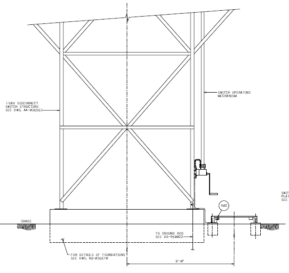
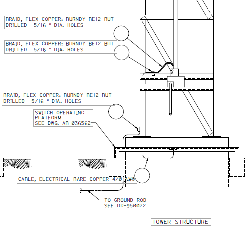
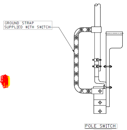
- Manually operated switches for overhead power lines shall have operating platforms and be grounded as shown on a standard following drawings.


- Underground ground conductors shall be insulated when within 3 meters of buried metal pipeline or metal piping.
- Underground ground conductors electrically connected to buried pipelines, buried metal vessels, or metal tanks sitting on grade shall be insulated. The associated ground earth rod shall be galvanized steel if the area is subject to cathodic protection.
- Grounding conductors extending through concrete or asphalt shall be run in PVC conduit (preferred) or PVC coated rigid steel conduit. Grounding conductors in steel conduit shall be bonded.
- s. Grounding conductors which do not accompany associated power conductors in the same conduit shall not be installed in metallic conduit except where PVC conduit is not suitable and it is necessary to protect the conductor from mechanical damage.

To understand “what is earth” see the topic above.
Fence Grounding
- a) Electrical substation fence shall be grounded as follows:
- Substation fences shall not be PVC coated and shall be grounded in a minimum of two locations to the local ground grid or loop.
- All fences for substations containing equipment fed from solidly earthing system operating at above 1 OOOV line to line shall be bonded to a grounding conductor buried approximately 1 m outside the fence and parallel to the fence.
- A second conductor shall be buried 1 m inside fence if the substation ground grid does not extend into this area.
- The grounding conductor(s) shall be connected to the substation ground grid at a minimum at four locations spaced equally around the loop.
- The fence shall be shall be connected to the grounding conductors at interval not exceeding 15m.
- Corner posts and gate posts shall be connected to the grounding conductors. Gates shall be bonded to the gateposts with connectors.
To understand “what is earth” see the topic above.
Termination and Torqueing
1 Grounding conductors shall be soft drawn copper.
2 Buried grounding conductor shall be annealed bare tinned copper.
3 All compression connector shall be tinned copper.
4 Compression (crimped) type connectors shall be used for splicing and terminating stranded conductors.
5 Compression terminal connectors for 4/0 and larger conductors shall have two holes NEMA design.
6 All fasteners (i.e., nuts, bolts, washers, etc.) used to connect and assemble the grounding connection system shall be 316 SS.
7 In severe corrosive environments, 316 SS fastener shall be used.
8 Neutral (grounded) conductors shall be identified by colour white or grey, and insulated grounding conductors by colour green or green with yellow stripes.
9 Torqueing shall be done for grounding connection.
10 Graduated Torque Wrench shall have valid Calibration Certificates.
11 Torque values should be in accordance with Test Report Attachment 1-NETA 1999 Table 10.12.
To understand “what is earth” see the topic above.
INSTALLATION OF EARTHING AND LIGHTNING SYSTEM