The following article is about earthing system, earth electrode, earth rod and the most asked question what is earth or grounding. Here in this article will be describe about also Underground Grounding Installation, Above Grounding Installation, equipment grounding, Grounding Bus Bar Installation and how to do substation grounding.
Required Tools and Equipment for grounding
– Hydraulic Crimping Tool
– Thermite Weld & Accessories
– Cable Cutter
– Forklift
– Bobcat
– Skid Loader
– Stakebed Truck
– Bore hole drilling machine
– Ladders & Scaffolds
– Cable Stripper
– Splicing Knife
– Electrical Pliers
– Ground Tester
– Cadweld Powder (Weld Metal)
– Exothermic Mold
– Mold Holder
– File diff. size
– Cable Cleaning Wire Brush
– Mould Cleaner
– Flint Gun
– Ground Earth rod Clamp
– Grounding Pit
– Ground Earth rod Coupling & Driving Stud
– U-Bolt Ground Clamp
– Other Relevant Tools
What is Earth or Grounding
In electrical, electronics and instrumentation engineering, earth is use for reference point to measure the voltages and it is also return path of current. It is directly or physically connected with the earth. Its main use for safety and other reason also.
Grounding / Earth
- Install earthing system cables, earth rods and accessories as depicted on IFC drawings. Install products in accordance with manufacturer’s instruction, approved drawings and Job Specifications, including Saudi Aramco Electrical Installation drawings.
- Excavation and backfill shall be carried out in accordance with international standard.
- Verify that final backfill and compaction has been completed before driving any earth rod earth electrodes into the ground.
- Install grounding / earth earth electrodes at locations indicated on IFC drawings and job specifications. Ground wells shall be installed and equipped with removable covers for maintenance access to the ground rods and their mechanical connections.
- All surfaces for grounding connections shall be thoroughly cleaned before the connections are made.
- Grounding termination/ connection shall be providing shrinkable sleeve.
- On the steel plate grounding provision an anti-corrosion paint shall be applied after the terminal lugs connection.
- For the grounding loop interconnection with the other package beyond the battery limit, shall have a clear agreement whose will be the in-charged on the connection.
- Following completion of installation, submit “Request for Inspection” (RFI) to site QC Section, indicating scheduled time / date for inspection.
To understand “what is earth” see the topic above.
Underground Grounding Installation
- Check and confirm the actual underground grounding routing for installation against approved construction drawings.
- Layout the grounding grid cable trench by marking using white pulverized powder the areas to be excavated.
- Excavation work shall be in accordance with international standard.
- Excavation shall be performed as required by the design drawings, to the dimensions, grades, and elevation as noted and required.
- All buried grounding conductor shall be installed at a minimum of 460 mm below grade.
- Underground grounding cable connection shall be performed using exothermic connection.
- Ground cables crossing access way shall be run in duct banks or PVC conduits.
- Buried grounding cables shall have clearance of 300 mm (minimum) from any underground obstruction.
- Where there are earth connections between feeders & branches are located in the cable trench, ensure that joints have been connected and tapped before back filling.
To understand “what is earth” see the topic above.
Above Grounding Installation
- Check and confirm the aboveground grounding routing for installation against approved construction drawings.
- All Earthing system points to be checked as per the drawing.
- Earth wire leaving the ground (stub-up) shall be protected by PVC conduits or RGS conduit.
- Sealing for stub-up PVC conduit or RGS conduit.
- The end(s) of ducts and conduit terminating below or in open air shall be sealed with duct sealing putty or an equivalent compound.
- All above ground cable connections shall be compression type.
- All cable Trays are to be bonded together and to the main ground grid with a 70 mm2 green PVC insulated copper ground conductor at interval not exceeding 25 meters apart.
- Frames of Medium Voltage motors shall have at least two (2) ground connections.
- Ensure a complete As-Built record of grounding installation is maintained for above and below ground (Red line/ Mark-Up).
To understand “what is earth” see the topic above.
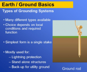
Grounding Earth rod Installation
- Ground Earth rod shall have the following characteristic:
- Bare copper or copper jacketed steel or galvanized steel.
- Have a minimum length of 2.4 meters. Jointed rods are permitted but each joint must be at least 2.4-meter long.
- For copper or copper jacketed steel rods be minimum of 16 mm in diameter and for galvanized steel rods be a minimum of 19 mm diameter.
- Install the grounding earth rod and accessories as depicted on the IFC drawing.
- Excavation and backfill shall be carried out in accordance with international standard.
- Verify the final backfill and compaction has been completed before driving the ground rod.
- Having confirm the soil final backfill and compaction, install the ground earth rod by driving using a light hammer, or mechanical, pneumatic or gasoline powered ground earth rod drivers.
- Continue driving until the desired depth is obtained.
- Below ground connection to the grounding grid or ground earth rod or between conductors and or grounding rods shall be made using one of the following methods:
- By thermite welding or brazing
- By approved compression grounding connectors.
- For connection at ground test station only where it is necessary to disconnect ground conductors for tests, approved mechanical connectors may be used.
- When using Thermite weld/ Cadweld, the following step shall be performed:
- Prior to making a connection, the detailed instruction and safety precautions provided by the manufacturer should be read properly.
- Sub-contractor will conduct training for skilled manpower to do thermite weld and cadweld.
- Clean the upper tip of ground earth rod and the conductor with approved cleaning solvent.
- Place the grounding earth rod and cable mould and close handle to lock mould.
- Drop metal disk and weld metal into the mould.
- Sprinkle starting material over weld metal and on lip mould.
- Close cover and ignite.
- Open cover after weld metal solidifies.
- Inspect weld per manufacturer’s recommendation. Coat weld with bituminous paint and adhesive PVC insulation tape.
- Prior to priming exposed area, clean substrate to bright metal.
- Thermite weld connection is not recommended in areas where a hazardous fire atmosphere may exist during the attachment process.
To understand “what is earth” see the topic above.
Grounding Bus Bar Installation
- Install grounding bus bar and accessories as depicted on IFC drawings.
- Install products in accordance with manufacturer’s instruction, approved drawings ad specifications.
- Ground Buses in Switchgear, Switchboard, and MCC shall have two connections to main grounding / earth earth electrode / grid.
- Grounding plate / bus bar fixed on concrete shall be installed using a pre arrange anchor screw on masonry concrete wall at elevation as per drawing and standard.
- Grounding plate / bus bar fixed on metallic structures shall be installed using head bolts welded on flat surface of metallic structure at elevation as per drawing and standard.