This article is about All transformer testing at site and at factory. Transformer testing basic concepts & Winding Insulation Resistance, Dielectric test discussed here. The object of factory acceptance tests carried out on transformers is to enable determination of their electrical characteristics and reliability of the manufactured quantity.
Transformer Testing Methods | FAT Tests | All Transformer Tests
In accordance with the requirements of IEC 60076 or ANSI C57.12.00, all STC Transformers are subjected to the following routine test in order to make sure that they meet the guaranteed performance.
- Measurement of Winding Resistance
- Measurement of Voltage Ratio and check of Phase displacement
- Measurement of Short Circuit Impedance and Load Loss
- Measurement of No-Load Loss and Current
- Dielectric Routine Test
- Induced Voltage dielectric Test
In the test certificate the characteristics of the Transformers, guaranteed values and the measured values are mentioned. The standard of construction and qualification are likewise indicated.
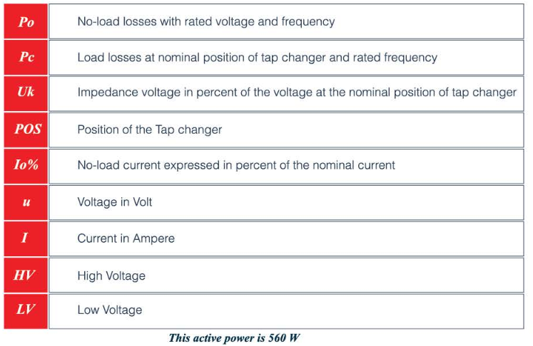
NO LOAD LOSSED AND CURRENT
Definition:
The no-load losses (iron losses) are equal to the power the Transformer takes when fed by a voltage equal to the rated no-load voltage at the rated frequency provided that the Transformer is not loaded. These losses consist of:
- Eddy current losses
- Hysteresis losses
- Joule losses (negligible)
- Dielectric losses (negligible)
Measurements:
Fig. No.1 Shows the schematic circuit for measuring the No load losses & and no load current.

No-load losses:

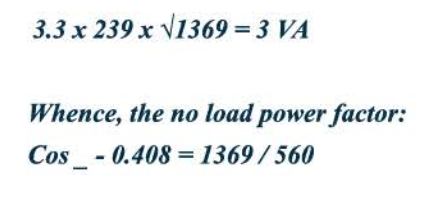
The above table shows the values indicated by Power Analyzer. The current measured 0.3015 and 0.2523 Amps in the phase U & Wand only 0.2055 Amps in phase V. This difference is due to the asymmetry of the magnetic core. We may accept the no-load losses remain constant at all temperatures.
The power factor at no-load can be calculated from the above mentioned measurements. The apparent power is equal to:
LOAD LOSSES AND IMPEDANCE VOLTAGE
Definition:
The load losses equal the power that has to be supplied and taken on the primary side when the secondary windings are short circuited and ‘the primary side is connected to an alternating voltage of such a value that the rated current flows through the secondary windings. One admits that, when the rated current flows through the primary windings it also does through the secondary windings.
Measurements:
Fig. No. 2 shows the schematic circuit for measuring the load losses and impedance voltage.

Load Losses at 29 °C

Three phase values of impedance voltages are recorded as 447 V. The current in each of the phases of the HV windings also recorded. The average of the three values is taken into account for the calculation. The algebraic sum of the readings gives us the value of the load losses.
The losses are generally guaranteed at a reference temperature of °85C. To convert these losses to this reference temperature of 85 °C, it is necessary to know the joule losses and the extra losses. Therefore, the ohmic resistance of the windings must be determined.
Remarks:
The load losses can be measured at a current Im ≠ In. The impedance voltage at rated current In will then be:

Index ‘m’indicates the measured values. Index ‘n’indicates the rated values.
TRANSFORMER WINDING RESISTANCE TEST
For measuring the ohmic resistances, the Volt-Ampere meters method is used. Fig.No.3 shows the schematic arrangement.
Fig.No.3 Measurement of Winding Resistance

The voltmeter is connected directly to the terminals of the Transformer. A 24V battery supplies the circuit with a direct current (DC) while a variable resistance R is used for limiting the current.

Th e values are always measured between lines, no matter what system of connection is used. Column Res . gives the value of the resistance between phases (3 each time) . In the last column the average value of the preceding division is given.
CALCULATION AT 85 °C
In general, the characteristics of a Transformer are guaranteed at a winding temperature of 85°C. Therefore, it is necessary that the load losses, the impedance voltage which are measured at ambient temperature of 29 °C, be converted to 85 °C. One can assume that the no-load losses remain constant at temperature of between- 20 oc and + 120 °C.
We know that the certain load losses (Joule losses) are proportional to the ohmic resistance of the windings Wcu- P2R.
For pure metals, the relation between resistance and temperature is the following

Where, the value T depends on the metal used. For copper T = 234.5. Using the above formula, we can obtain the resistance at 85 C.
![]()
In addition to the Joule losses, still other losses occur in the copper: the losses due to the skin effect and the losses due to the stray currents or losses by hysteresis. These extra losses (CONN) equal W cu- I 2R.
It is admitted that with a variation in the temperature, the extra losses (CONN) vary in an inverse proportion to the variation in the resistance
TRANSFORMER VOLTAGE REGULATION
The general formula for calculating the voltage regulation in % of the line voltage for a given power factor is:

Now, we know all the values for the windings at 85C

TRANSFORMER DIELECTRIC TESTS
Two tests are conducted under this caption. The purpose of these two tests is to determine the insulating properties between the windings and the earth
A) Separate source Voltage withstand Test
Between the primary winding and the secondary winding, an alternating voltage is applied the value of which depends on the insulation level of the Transformer. Thus, for 11.0 kV Transformers, a voltage of 28kV is applied for 1 minute on the primary winding while the secondary winding and the tank are earthed. In the LV Side, a 3 kV is applied between the secondary windings and the earthed tank. Fig. No.4 shows the circuit diagram for Separate Source Voltage withstand test.
Fig. No. 4. Separate Source Voltage Withstand Test (for HV Winding)

B) Induced over Voltage withstand Test
The induced over voltage test is a test of the insulation of the windings. The Transformer is fed twice the nominal voltage at a frequency minimum double the rated frequency and to allow 7,200 cycles to pass through the Transformers as per IEEE C00-12-57 .So the Transformer is fed with twice the nominal low voltage at a frequency 150Hz instead of 60Hz for a period of 48 seconds. The higher frequency is necessary to limit the no load current. During this test, the voltage between adjacent turns has a value twice as high as under the normal working conditions. Fig. No. 5 shows the circuit diagram for Induced Over Voltage withstand test.
Fig. No. 5 Induced over Voltage withstand Test

TRANSFORMER INSULATION RESISTANCE
The resistance of the insulation between HV & LV and the tank is measured by Megger of a minimum of 1000 V and is expressed in Mega Ohms. Fig. No. 6 shows the circuit diagram for Measurement of Insulation Resistance.
Fig. No. 6 Measurement of Insulation Resistance (Between HV to Earth)

TRANSFORMER VOLTAGE RATIO AND VOLTAGE VECTOR
Definition:
The transformation ratio, taking into account the tapping used, is the ratio between the voltages of HV windings and LV windings. When the transformer is not loaded, the voltage ratio is generally equal to the turns ratio provided the voltage drop due to no load current neglected.
Measurements:
To enable measuring the ratio with great accuracy, there now exists a measuring bridge. The bridge enables us to measure the ratio between two voltages which are in phase and have the same sense vectorially.
The table below gives the results of the turns ratio measurements, taking into account the various positions of the charger.
The HV / LV column contains the theoretical values, and the other column produces the real measured values. Fig. No. 7 shows the circuit diagram for Measurement of Turns Ratio.
Fig. No. 7 Measurement of Turn Ratio

VOLTAGE RATIO / VECTOR GROUP
