VESSEL, DRUM, TOWER ASSEMBLEY PROCEDURE
1. Preliminary
The purpose of this procedure is to describe the installation of FRP-made internals into the Washing Drum. Internals assembly shall be performed under Axens (or Aubert) representative supervision.
1.3 Vessel status
General status of the vessel’s FRP Lining has been checked and released at vessel vendor’s shop by Authorized Inspector (refer to Inspection Release Note).
Once on site, the vessel shall not be opened without getting the preliminary agreement given by Axens (or Aubert) representative in charge of the installation supervision.
Vessel shall be in vertical position.
1.2 Internals status
Final inspection of the internal parts has been carried out at AUBERT shop by Axens Representative (refer to Inspection Release Note).
Once on site, the crates shall be stored inside a warehouse, and if not possible properly protected with dedicated plastic covers.
All pieces of internals shall be carefully handled and stored to prevent inclusion of foreign materials and/or exposure to temperatures below 10°C or exceeding 30°C.
1.3 Equipment and personnel
- Drum being internally coated, special care shall be taken all along the assembly phases so as to avoid any detrimental damage on the applied liner:
Manhole and Nozzles Flange faces must be protected against impact by rubber sheet (thickness 3 mm mini). These sheets could be hold by adhesive tape. - No FRP made equipment shall be laid at ground without ensuring protection has been provided. Handling and lifting of internal parts shall be performed with care all along the different phases.
- No metallic wire shall be used. Lifting of the two beams (steel made with FRP coating), and other parts as well, shall be performed one by one by using dedicated ropes.
- Ladders which have to be introduced into the vessel shall preferably be made with wooden parts (same request for scaffolding if needed). If no wooden made ladders are available, metallic bearing parts shall be protected with protective neoprene sheets (thickness JO mm mini). This must be respected to avoid damage on liner.
- No metallic grinding is authorized into the vessel.
- Special care must be taken when using metallic tools. Down falling of metallic tools (even if only few are needed for the purpose) may induce detrimental damage on the FRP coating. In the aim at reducing the risk as far as possible, bottom part of the vessel will be fully protected by neoprene sheet (or equivalent) to prevent such a problem.
- No Safety shoes shall be allowed inside the vessel. Workers will wear dedicated shoes paper made protection
or rubber soled shoes to avoid foreign particles entrance during assembly operations.
2. Schedule
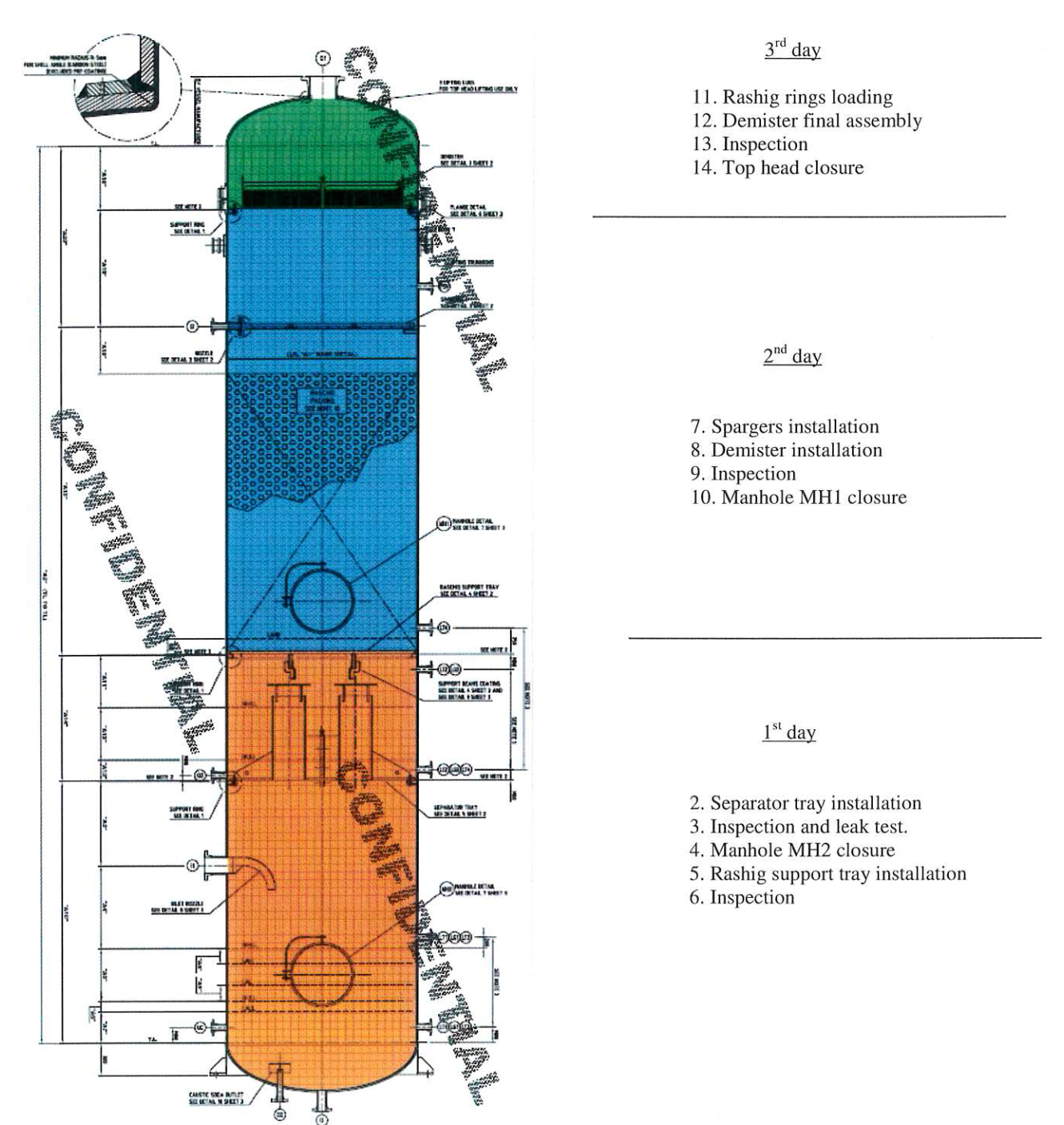
Here after is a typical assembly schedule showing required inspections and manhole closures. Installation can be completed within 3 days:
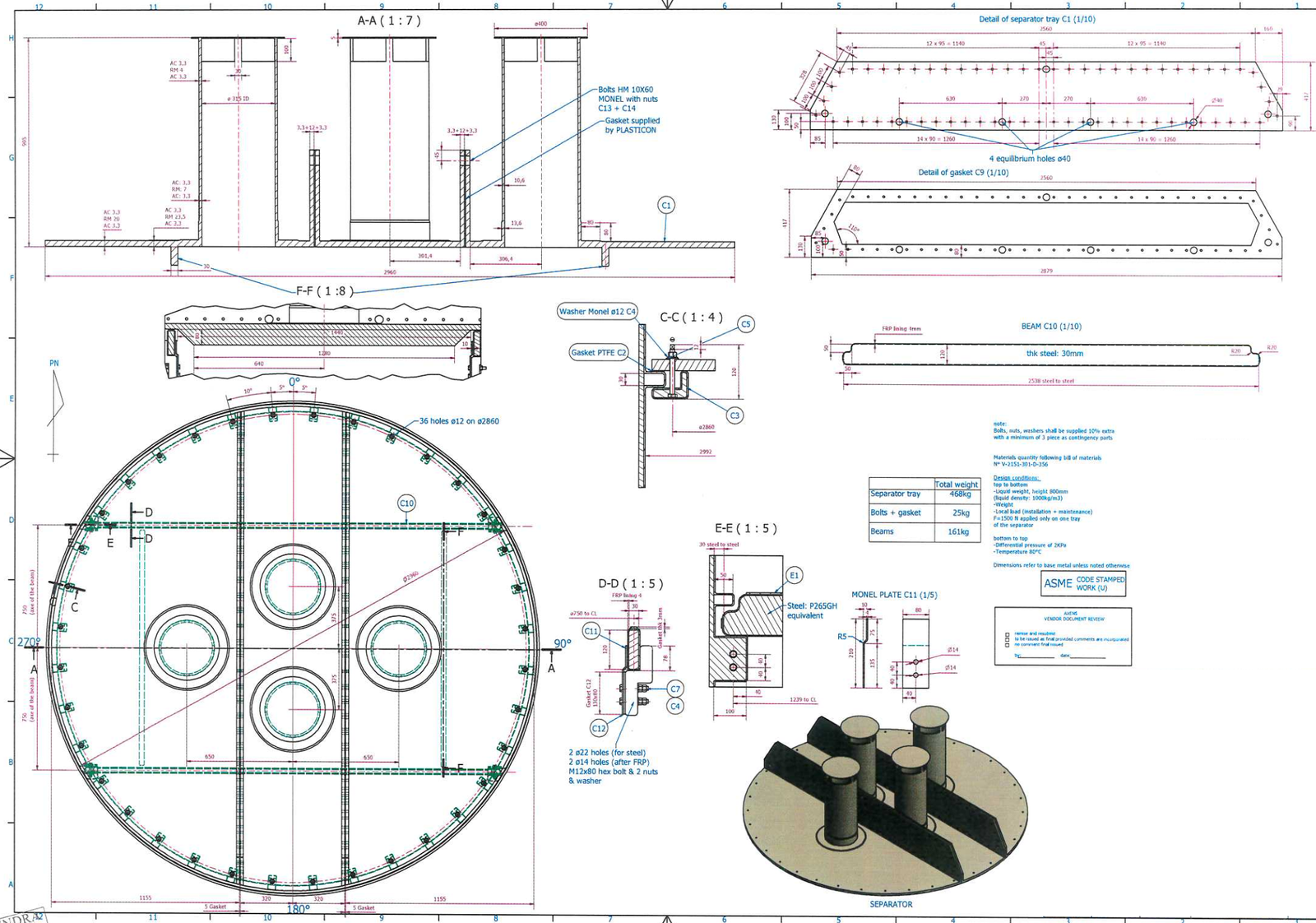
3. Separator Tray Installation
- Provide access to the support ring (refer to 1.3).
- Introduce the first part of the separator tray using dedicated lifting lugs (refer to 1.3)
- Once entered into the vessel, re-put the tray panel in horizontal position (during tray panel handling, installation and positioning, special care shall be taken to avoid any interference with the lining of the vessel).
- Lay the tray panel on its support ring.
- Put inside the last part of separator tray in same way.
- Once all parts of separator tray are laying on the support ring, install the dedicated gasket. Perform the final bolting of the tray (a worker will reach the Separator Tray top face), Specified tightening torque: 20 N.m (Max 30 N.m)
- Lift the separator tray of about 50mm.
- Install expanded PTFE gasket on the support ring. Use silicon on gasket lower surface in order to stick it on the support ring. Do not stick the gasket to the tray.
- Put the separator tray back in place in its final position.
- Install and tighten the clamps.
- Specified tightening torque: 5 N.m (Max 10 N.m)
- Remove every foreign material from the bottom part of the vessel.
- Inspection of separator tray assembly.
- Perform separator tray leak test:
- introduce water up to the stiffening beam
- make sure there is no free flow trough the tray (30 /h maximum)
- Inspection of bottom coating. In case of impact found during final inspection, Aubert repairing procedure shall be followed (procedure “QREP SVR/ACJER”).
- Close bottom manhole MH2.
4. Rashig Ring Support Tray Installation
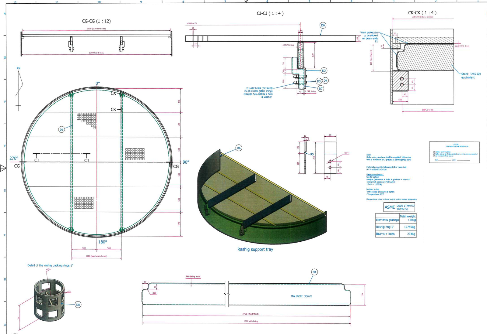
- Introduce support beams into the drum though the top MH in vertical position (refer to 1.3),
- Beams assembly and clamping onto the beams support (refer to drawing 3/5). Specified tightening torque: 15 N.m
- Inspection of rashig ring support tray beams and coating. In case of impact found during final inspection, Aubert repairing procedure shall be followed (procedure “QREP SVR/ACIER”). Rashig ring support tray panels
installation shall be performed under Axens supervision. - Introduce the first panel through the top MH and put it on the support ring and the two beams (refer to 1.3).
- Install the last panel. The tray shall be centred on the support ring (distance between tray and vessel wall should be kept at 16mm all around the circumference).
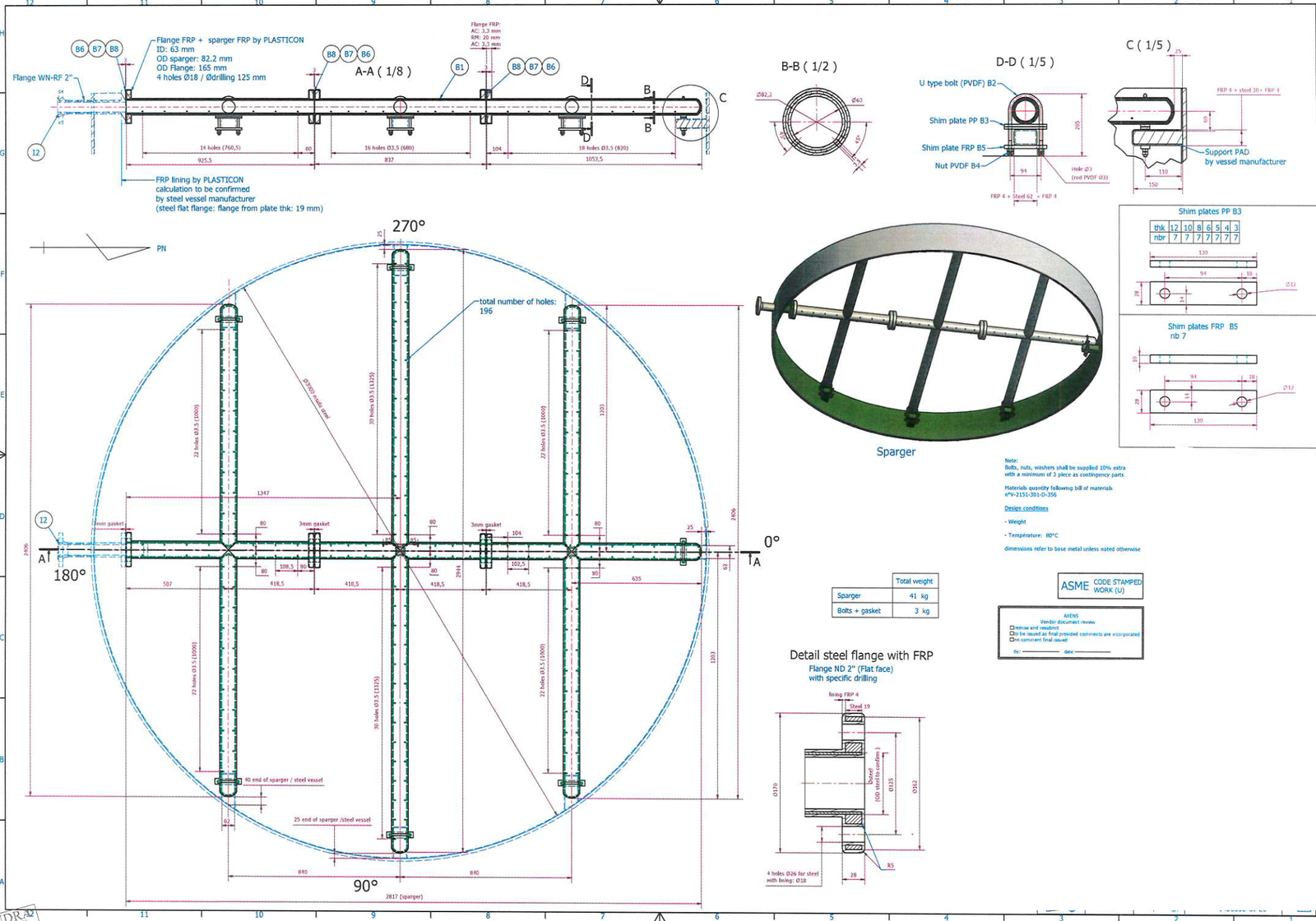
5. Spargers installation
- Raschig ring support tray shall be protected with a temporary wooden plate (thickness 15 mm).
- Provide access to the connecting flange of sparger (refer to 1.3).
- Introduce sparger parts into the drum though the top MH (refer to 1.3).
- Assembly of the 3 connecting flanges (refer to drawing 2/5) Specified tightening torque: 5 N.m (Max 10 N.m).
- Adjust the remaining clearance (if any) between the pipe ends and their supports by use of PPH shim plates (refer to drawing 2/5). Bearing contacts must be recovered for all tube ends.
- Install “U” type Bolts (refer to drawing 2/5) Specified tightening torque: 5 N.m.
6. Demister installation
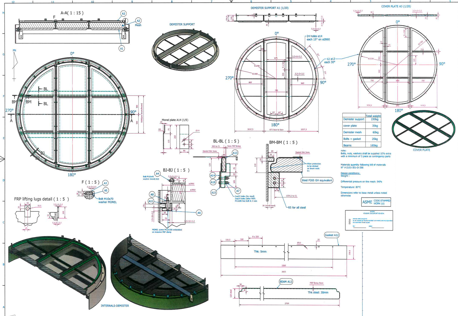
- Introduce the first part of the demister using dedicated lifting lugs (refer to 1,3).
- Install the last parts of demister on support beams and support ring. The jointing face of demister support parts must be perpendicular to the beams (refer to drawing 2/5). Specified tightening torque: 5 N.m (Max I0 N.m)
- Install and tighten the clamps. Specified tightening torque: 5 N.m (Max 10 N.m)
- Inspection of spargers and demister bottom.
- Remove the ladder or scaffolding and all other foreign materials which could remain between Raschig ring support tray and demister support.
- Visual checking of the coating between rashig ring support tray and the demister. In case of impact found during final inspection, Aubert repairing procedure shall be followed (procedure “QREP SVR/ACIER”),
- Close side manhole MH1.
Rashig rings loading
- Install a wooden floor (for one person) on one side part of the demister.
- Remove the other side part of the demister mesh in order to create proper access for raschig rings loading.
- Load the raschig rings through the opening.
- Put the demister back in place and finalize the tightening (demister and clamps). Inspection of top part coating and demister top. In case of impact found during final inspection, Aubert repairing procedure shall be followed (procedure “QREP SVRACIER”),
- Remove the temporary wooden floor.
- Close top manhole.
Vessel shall not be opened without getting agreement given by Axens (or Aubert) representative.
Details of Separator Tray
Details of Sparger
Drawing of Demister Tray
Details of raschig Support Tray
