1.0 PURPOSE.
2.0 SCOPE.
3.0 APPLICABLE DOCUMENTS.
4.0 RESPONSIBILITY.
5.0 MANPOWER.
6.0 TOOLS & EQUIPMENT.
7.0 METHODS/PROCEDURES.
8.0 QUALITY CONTROL.
9.0 SAFETY PRECAUTION.
10.0 ATTACHMENTS.
1.0 PURPOSE:
1.1 This method statement shall provide minimum Guidelines for installation of Vessel, Tower and Drum Internals for plants and refineries in accordance with Project Drawings and Project Specifications.
1.2 Internals assembly shall be performed under AXENS (or Aubert) representative supervision.
2.0 SCOPE:
2.1 This specification covers the minimum requirements for installation of Vessel, Tower and Drum internals to be applied at plants and refineries.
3.0 APPLICABLE DOCUMENTS:
3.1 ARAMCO Project Specifications and Standard.
3.1.1 SAEP-302 Instruction for obtaining a waiver of a mandatory Saudi ARAMCO Engineering requirement.
3.1.2 SAES-H-101V Approved Saudi Aramco Data Sheets-Paint and Coatings.
3.1.3 SAES-L-350 Construction of Plant piping.
3.1.4 Related Vendors Installation and maintenance manuals/procedure and /or specifications.
3.2 Inspection and Testing Plan
3.2.1 SATIP-D-001-01 Typical Inspection Plan Pressure Vessel Installation.
3.2.2 SAIC-D-2001 Review of Vessel Safety Instruction Sheet & Procedure for Vessel Internal Component Installation.
3.2.3 SAIC-D-2003 Receiving Inspection of Pressure Vessels- Internal.
3.2.4 SATR-D-2003 Vessel Closure Inspection Certificate.
3.2.5 SATR-D-2004 Tray Test Report.
3.2.6 SAIC-D-2009 Installation & Inspection of Trays & Packing in Vessels (Special Construction Process Procedure).
3.2.7 S-000-3151-003 Specifications for Tray Work.
3.3 Latest Revision of the following Documents shall be used.
3.3.1 Vendor Drawings
3.3.2 Equipment Details
3.4 Saudi ARAMCO Safety, Health and Environmental Standard:
3.4.1 Construction safety manual — compliance with schedule D.
3.4.2 General Instructions (G.l’s) at the work site.
4.0 RESPONSIBILITY:
4.1 Construction Manager is responsible for implementing HSE, study, analyze and
schedule all construction activities with his department to
include manpower and
equipment line up as well as other possible resources required for the successful
implementation of the construction work activities. Study all aspects of work
procedure as per DEC/JGC technical Scope of Work and Saudi Aramco Standard.
4.2 Mechanical Supervisor shall study and review all necessary documents for the
application activity in his area to include, technical scope of work, specification, bill of
quantities, planned milestone dates and construction procedure in support to his
Mechanical Foreman. He shall monitor the availability of materials in accordance
with the schedules and construction analysis. He shall be directly reporting to the
Construction Manager. He shall coordinate with other discipline to visualize
possible conflicts in the drawings as well as in the schedules to provide other options
in preventing unnecessary delays and obstructions.
4.3 Mechanical Foreman shall be responsible for the direct work supervision at site and
ensure that the work is performed in accordance with DEC/JGC Technical Scope of
Work, Saudi Aramco Standard and latest approved for construction drawings. He
shall monitor the availability of materials in line with his required schedule.
4.4 QC Inspector shall be responsible in monitoring and
inspection of the work and
ensured that the work is performed and properly documented
in accordance with Technical Scope of Work and Saudi Aramco Standard.
4.5 Safety Officer/Supervisor shall be responsible
in monitoring safety aspects and
ensuring that the work
is done
in accordance with Safety Standard
Procedure and Saudi Aramco Construction Safety Manual. He shall discuss to the
workers the characteristics of related materials and Status of work area giving
reminders as an additional point to work safely.
5.0 MANPOWER
5.1 The Mechanical Supervisor shall control the overall activity on installation of internal. The basic manpower under him shall consist but not limited to the following:
5.1.1 Foreman mechanical
5.1.2 Mechanical Fitters/ Internal installer
5.1.3 Laminator (if required)
5.1.4 Helper
5.1.5 Scaffolder (by others)
5.2 Safety Engineer
5.3 QC Inspector
6.0 TOOLS AND EQUIPMENT;
6.1 Tools and equipment needed should be in good condition and must be checked by
Mechanical Supervisor/Safety Officer prior to use in the construction area. These
Includes but not limited to:
6.1.1 Wooden Ladder/ Aluminum ladder with rubber sheet
6.1.2 Chain blocks
6.1.3 Lightings
6.1.4 Chalk or Paint stick
6.1.5 Spirit Level
6.1.6 Portable air analyzer with alarm device
6.1. 7 Portable moisture and temperature analyzer
6.1.8 Bravo/ Radio for communication
6.1.9 Flashlight
6.1.10 Vacuum cleaner
6.1.11 Dust mask
6.1.12 Air Mask
6.1.13 Paper shoes/ rubber soled shoes
7.0 METHODS/ PROCEDURES INSTALLATION OF VESSEL, TOWER AND DRUMS INTERNALS :
7.1 Jobsite Receiving and Inspection:
7.1.1 Upon withdrawal and receipt of materials from warehouse, receiving inspection shall be conducted immediately.
7.1.2 Record of inspection shall be documented as per applicable SAIC (Material Receiving Inspection); findings and deviations shall be documented in Quality control Inspection Report (QCIR) and Non Conformance Report (NCR).
7.1.3 Once on site, the crates shall be stored inside a warehouse, and if not possible properly protected with dedicated plastic covers.
7.1.4 Internals shall remain in their crates up to the beginning of the assembly. Opening will be officially authorized by Plasticon Aubert or Axens representative.
7.2 Preparatory Works
7.2.1 Secure all the valid documents such as confined space permit prior to work commence.
7.2.2 Tools and equipment shall be made operational and available for use. Ensure tools are color-coded accordingly
7.2.3 Mobilize all manpower, tools and equipment needed for the job.
7.2.4 Manpower who will do the job should secure training on confine space and necessary training to do the job at Daewoo.
7.2.5 Install barricades to confine the area for authorized personnel only.
7.2.6 Internal site assembly shall be performed under Axens or Plasticon Aubert Representative Supervision as requested into Axens specification.
7.2.7 Special care shall be taken all along the assembly phases so as to avoid any detrimental damage on the applied liner. No unauthorized entry without prior approval delivered by responsible person (Vendor/JGC).
7.2.8 Special care must be taken when using metallic tools. Down falling of metallic tools (even
if only few are needed for the purpose) may induce detrimental damage on the FRP coating. In the aim at reducing the risk as far as possible, bottom part of the vessel will be fully protected by neoprene sheet (or
equivalent) to prevent such a problem.
7.2.9 In case of ladder use, ladder shall be protected with rubber sheet as the place of contact with FRP Lining.
7.2.10 Ladders which have to be introduced into the vessel shall preferably be made with wooden parts (same request for scaffolding if needed).
If no wooden made ladders are available, metallic bearing parts shall be protected with
protective neoprene sheets (thickness 10mm min.) This must be respected to
avoid damage on liner.
7.2.11 No metallic grinding is authorized into the vessel.
7.2.12 No safety shoes shall be allowed
inside the vessel. Workers will wear
dedicated shoes paper made protection or rubber soled shoes to avoid
foreign particles entrance during assembly operations.
7.3 Vessel Preparation
7.3.1 Opening of two manholes to create proper accesses for internal assembly.
7.3.1.1 No FRP made equipment shall be laid at ground without ensuring protection has been provided.
7.3.1.2 Manhole and nozzle face flange must be protected against impact by rubber sheet (3mm thick minimum). These sheets could be hold by adhesive tape.
7.3.1.3 Handling and lifting of internal parts shall be performed with care all along the different phases.
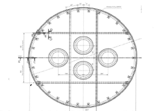
7.3.2 Installation of separator tray (V-2151-301-D-354)
7.3.2.1 Provide access to the ring support level (ladders or scaffolding
protected with rubber sheets.
7.3.2.2 Support beams shall be introduced into the drum through the top of
manhole in vertical position.
7.3.2.3 All parts as well, shall be performed one by one by using web sling with rigging tackles covered by soft materials such as clean cotton rugs or wrapped by rubber material. Refer to attachment C for weight of each material for lifting. Beams assembly and clamping into the beams support.
7.3.2.4 Separator tray lifting

7.3.2.5 Once entered into the vessel, the tray panel will have to re-put in
horizontal position. During tray panel handling,
installation and
positioning, special care shall be taken to avoid any interference with
the lining of the vessel.
7.3.2.6 Tray panel shall be laid on its support ring
7.3.2.7 Once in place, the tray panel shall be so as that the stiffening beam is
perpendicular with the support beams axis. Bolting of the two tray
parts will beam carried out through these stiffening beams.
7.3.2.8 Put inside the second part of separator tray in same way.
7.3.2.9 Once the tray installation on support ring complete, a worker will reach the separator tray top face so as to perform the final bolting of the tray.
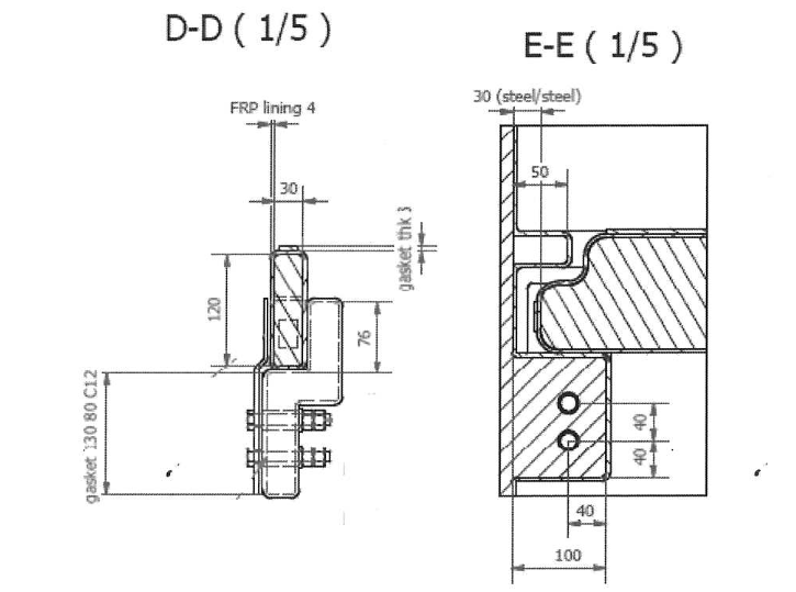
7.3.2.1 O A dedicated gasket shall be installed prior to perform the bolting.
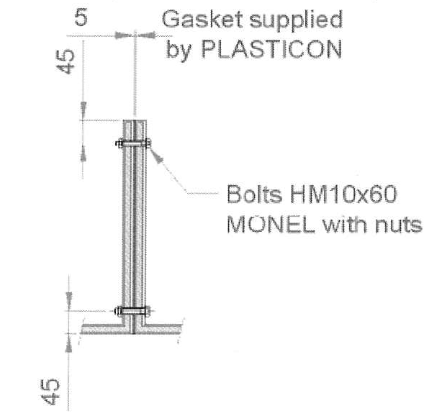
7.3.3 PTFE gasket installation
7.3.3.1 Once the bolting informed, the separator tray shall be lift: uplift of about 50mm
7.3.3.2 Expanded PTFE gasket to be installed on support ring. Use silicon on gasket lower surface in order to stick it on the support ring. Do not stick the gasket to the tray.
7.3.3.3 Put the separator tray back in place in its final position.
7.3.3.4 Install and tighten the clamps

7.3.3.5 The separator tray is in its final position.
7.3.3.6 Every foreign materials, if any, shall be remove from the bottom part of the vessel (through the bottom manhole)
7.3.3.7 Inspection of separator tray assembly.
7.3.3.8 Introduce water up to the stiffening beam; make sure no free flow
through tray (30 I/h maximum).
7.3.3.9 During final
inspection, coating will be checked to insure that no
impact has been performed on internal lining.
7.3.3.10 In case of impact found during final inspection, refer to Aubert repair procedure (procedure “QREP SVRIACIER”).
7.3.3.11 Close bottom manhole (MH2)
7.3.4 Installation of raschig support tray (V-2151-301-D-355)
7.3.4.1 Support beams shall be introduced into the drum through the top of manhole in vertical position.
7.3.4.2 No metallic wire shall be used unless wrapped by rubber or cotton. All parts as well, shall be performed one by one by using dedicated web sling.
7.3.4.3 Beams assembly and clamping into the beams support,
7.3.4.4 Inspection of raschig support tray beams and coating. In case of impact found during final inspection, Aubert repair procedure (procedure “QREP SVRIACIER”) shall be followed. Raschig ring support tray panels installation shall be performed under AXENS supervision.

7.3.4.5 Introduce the first panel through the top manhole and put it on the support ring and the two beams.
7.3.4.6 Before the installation of the last panel it is necessary to check the coating between the separator tray and the raschig support tray. The tray shall be centered on support ring (distance between tray and vessel wall should be kept. At 16mm all around the circumference.
7.3.5 Installation of sparger
7.3.5.1 Raschig ring support tray shall be protected with a temporary wooden plate (thickness 15mm). Once protective sheet in place, provide access to the connecting flange of sparger.
7.3.5.2 Introduce sparger parts into the drum through the top MH
7.3.5.3 Assembly of the 3 connecting flanges.

7.3.5.4 Adjust the remaining clearance (if any) between the pipe ends and their supports by use of PPH shim plates. Bearing contact must be recovered for all tube ends.

7.3.5.5 Install “U” type bolts.

7.3.6 Installation of the demister & raschig rings

7.3.6.1 Introduce the first part of the demister using dedicated lifting lugs

Install the last parts of demister on support beams and support ring. The jointing face of demister support parts must be perpendicular to the beams.
7.3.6.3 Inspection of spargers and demister bottom. Remove the ladder or scaffolding and all other foreign materials which could remain between raschig ring support tray and demister support.
7.3.6.4 Visual checking of the coating between raschig ring support tray and the demister. In case of impact found during final inspection, Aubert repair procedure (procedure “QREP SVR/ACIER”) shall be followed.
7.3.6.5 Close side manhole MH1.
7.3.7 Raschig ring loading
7.3.7.1 Install a wooden floor (for one person) on one side part of the demister.
7.3.7.2 Remove the other side part of the demister mesh in order to create proper access for raschig rings loading.
7.3.7.3 Load the raschig rings through the opening.
7.3.7.4 Push the demister back in place and finalize the tightening (demister and clamps).

Raschig ring loading
7.3.7.5 Inspection of top part coating and demister top/ In case of impact found during final inspection, Aubert repairing procedure shall be followed (procedure “QREP SVR/ACIER”)
7.3.7.6 Remove temporary wooden floor.
7.3.7.7 Close top manhole.
7.3.7.8 Vessel shall not be opened without prior approval from responsible person.
7.3.8 Repair procedure for FRP coating in the washing drum shall be done as per Aubert repairing procedure (procedure “QREP SVR/ACIER”).
7.4 Damages and Nonconformity
7.4.1 Any damages and defects and nonconformity found at site shall be reported immediately.
7.4.2 ARCC QC Inspector will be responsible for all required documentation.
8.0 QUALITY CONTROL
8.1 QC Personnel shall be assigned to ensure the quality control requirement of the project.
8.2 QC Personnel well coordinate with Client inspector to conduct inspection as required.
8.3 QC Inspector shall be responsible to conduct all required inspection/documentation and to ensure that all applicable requirements, codes, and standards are complied with SAIC/SATIP.
8.4 Contractor has to utilize the applicable SAIC for every activity.
9.0 SAFETY PRECAUTION
9.1 Obtain the approval of the work permit from the concerned Representative before starting any work.
9.2 Safe work execution shall be carried out in accordance with method statement. And in compliance with project specification.
9.3 Continuous monitoring and inspection shall be implemented to detect and correct unsafe practices while performing the work activities.
9.4 Person involve on this job shall have trainings especially in confine space and working at heights.
9.5 Provide warning sign and sufficient barricade on working area and only assigned personnel will be allowed in the area.
9.6 Worker shall wear PPE’s needed for the work.
9.7 Safety Supervisor/Officer shall monitor the work activities to help and to protect all assigned workers against exposure to safety hazards. He shall ensure that Personal Protective Equipment (PPE’s) are supplied and used and comply with applicable standards.
9.8 Housekeeping shall be maintained and working area shall be kept in a clean and tidy manner.
9.9 Job Hazard and Risk Assessment (JHRA) of this method statement shall be disseminated and explained to workers for safety awareness.
10.0 ATTACHMENT:
10.1 Attachment A Job Hazard and Risk Assessment (JHRA).
10.2 Attachment B Washing drum assembly procedure.