Elevator Commissioning and Testing Procedure | Method Statement
| 1. | General moving parts | Test, Visual Inspection | Correct lubrication of base enclosure and level doors |
| 2. | Base tower section | Visual Inspection | Welding line correct, formation of cracks |
| 3. | Tower sections | Visual Inspection | Welding line correct, formation of cracks |
| 4. | Mast connection screws | Test | Strength, tightening torque (350 Nm steel) |
| 5. | Mast ties | Test | Check all bolts at mast are tied like described in manual |
| 6. | Elevator car floor | Visual Inspection | no cracks, correct fastening |
| 7. | Drive leak proof | Visual Inspection | Gearbox leak proof (dry) |
| 8. | Gearbox oil | Test | Lifetime-lubricated |
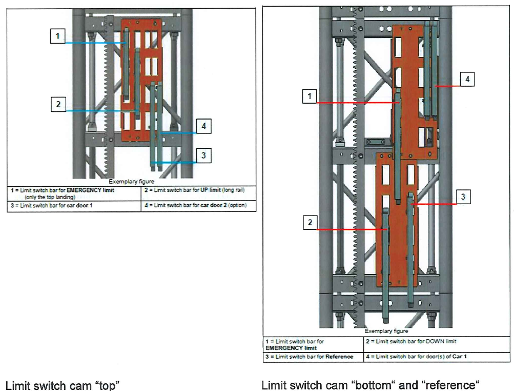
| 9. | Start-up cams for limit switches | Visual Inspection | Availability, no damages, see setting values |
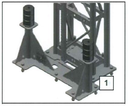
| 10. | Buffer, buffer receptacle | Visual Inspection | Check that there is no damage |
| 11. | Pinion, racks | Visual Inspection | Damage, wearing |
| 12. | Lubrication of pinion, | Visual Inspection | Check that grease comes out of pipe of the grease supply |
| 13. | Guide rollers | Visual Inspection | Wearing, tolerance, condition of bearing, locking ring |
| 14. | Roof hatch | Visual Inspection | Function of locking device, grease the hinges |
| 15. | Car door | Test | Visual inspection, function of interlocking device, lubricate guides and interlocking device |
| 16. | Base enclosure | Visual Inspection | Clearance according GA-drawing, stability |
| 17. | Cable guides | Check | Location |
3 Electrical system
| 3.1. | Insulation of the cables | Visual Inspection | Check all cables that are installed on site | Support list for commissioning procedure |
| 3.2. | Insulation | Measurement | >0.5 MΩ for protection class 1, to be done by customer | Support List for Commissioning Procedure |
| 3.3. | Earth conductor resistance | Measurement | <0.3 Ω for protection class 1, to be done by customer | Support List for Commissioning |
| 3.4. | Cable routing | Visual Inspection | Cables get routed in cable channel of customer. Routing rules by customer | |
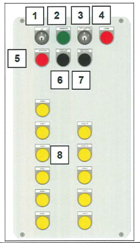
| 3.5. | Operating elements, buttons, switches | Visual Inspection, Test | Correct operation | Operation Manual: Section 12.3 and 12.4 (Operating and control elements) |
| 3.6. | Indicating elements, lamps | Visual Inspection, Test | Correct indication | Operation Manual: Section 12.3 and 12.4 (Operating and control elements |
| Fuses | Visual Inspection | Correct values of the fuses | Fuses are checked in manufacture factory. For information see the electrical diagram | |
| 3.8 | Return control | Function Check | Correct operation of return control | Operation Manual: Section 12.3.2 (Return control) |
| 3.9 | Lighting | Function Check | Correct operation of lighting | Operation Manual: Section 15.8 (Lighting) |
| 3.10 | Emergency telephone | Function Check | Correct operation of telephone | Support list for commissioning procedure |
4. Function
| 4.1. | Motor brake | Test Run | Stop at level 10mm higher or lower Brake test | Support list for commissioning procedure |
| 4.2. | Safety Gear | Test | Braking distance approximately 1 meter. Full stop criteria. | Support list for commissioning procedure |
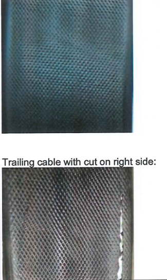
| 4.3. | Trailing cable | Visual Inspection | No cuts on trailing cable | Support list for commissioning procedure |
| 4.4. | Overload protection | Test | Switching off at 110% of max. payload | Support list for commissioning procedure |
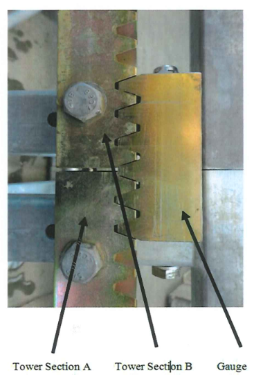
| 4.5. | Tower Sections | Test Run | Transitions | Support list for commissioning procedure |
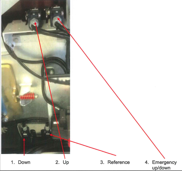
| 4.6. | Limit switches | Test | Correct function of limit switches | Support list for commissioning |
| 4.7. | Proximity switch | Test | Correct function of switch | Support list for commissioning |
| 4.8. | Landing doors | Test | Function of interlocking device, lubricate the hinges, Function of emergency unlocking device | Support list for commissioning |
| 4.9 | Car door | Test | Visual inspection, Function of interlocking device, lubricate guides and interlocking device | Support list for commissioning procedure |
5 Miscellaneous |
||||
| 5.1. Pit | Visual Inspection | Drainage of pit | ||
| 5.2. Access to elevator | Visual Inspection | Illumination of any access |
2. Mechanical
| 2.2 Base tower section |
Check the section for cracks and destructions. See pictures below. 1. No bended cross bars. 2. No cracks at connection positions. 3. No incorrect welding seam.
|
| 2.3 Tower sections | Same criteria like at 2.1 Base tower section. |
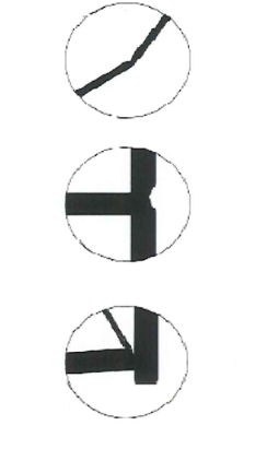
| 2.9 Start-up cams for limit switches. | Check the position of the cams.
|
| 2.10 Buffer, buffer receptacle.. | Check that the buffers are free of damages.
|
3. Electrical System
| 3.1 Insulation of the cables. | Check the cable for cuts and / or damages: Check all cables that were mounted during the assembly on site. Check the cables for optical cuts and / or damages. (You can also find the overview in the wiring diagram). |
| 3.2 Insulation. | Measurement of the insulation resistance of different circuits for this measurement the electronic components are to be disconnected. >0.5 MΩ for protection class 1. |
| 3.3 Earth conductor resistance. | Verification of the connection between the earth terminal of the machine room and the different parts to be made live accidentally. <0.3 Ω for protection class 1. |
| 3.10 -Emergency telephone. | Precondition for this check: telephone signal cable has to be connected to working telephone system |
| 4.1 Motor brake. | Test Run: Drive in automatic mode to any landing or to base enclosure. The car has to stop maximum 10mm higher or lower than level. |
| 4.2 Safety gear | Dynamic drop test of safety gear: 1. Put weights into the cabin. First drop test will be executed with 125% of maximum payload. 2. Execute the drop test (please refer Maintenance Manual section 9.6.1 ). 3. Reset the safety gear (please refer Maintenance Manual section 9.6.2). 4. The drop test must be carried out all 6 months. (please refer Maintenance Manual section 9.2). 5. The safety gear must be replaced all 3 years. (please refer Maintenance Manual section 9.2). |
| 4.3 Trailing cable. | Trailing cable (flat cable) have to be checked for cuts: Trailing cable without cut:
|
| 4.4 Overload protection. | Overload switching at 110% of payload. Put weight into the cabin. The overload alarm has to get activated at more than 110% of payload. Take a look at the red lamp at the control unit ( 4 ). Overload is activated if red lamp is on.
|
| 4.5 Tower Sections | Check the transition of the tower sections by using the rack gauge.
|
| 4.6 Limit switches (roof). |
Information: If the hoist is working in automatic mode (normal operation) then the hoist starts from the reference limit switch and the levels get reached by using the encoder. |
| 4.7 Proximity switches. | The inductive switches release the safety relay for the door locking. Proximity switch test. Drive to the base enclosure or any level. The sensors are working if the door gets released.
|
| 4.8 Landing door. |
Check landing door not to be opened during elevator operation. |
| 4.9 Car door. |
Check car door not to be opened during elevator operation. |
CHECKLIST FOR ELEVATOR FUNCTION TEST AND LOAD TEST