Keywords for this article are Vibration Probe accessory hardware installation. Internal Probe Mounting System. Probe Housing Assembly. Axial Position. Radial Vibration.
Vibration Probe accessory hardware installation
Radial Vibration
Two (2) more commonly use relative probe mounting systems are illustrated in Figures 11a and 11b.


Internal Probe Mounting System
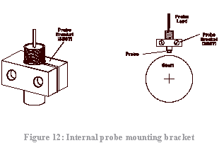
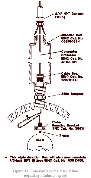
Probe Mounting Bracket, BNC Part Number 3567
The probe bracket is used for mounting the probes inside a machine case (see Figure 12). A threaded hole is provided to hold the probe and to allow adjustment of the probe tip in relation to observed surface. The other two 5.5 mm (0.218 inch) diameter holes are for attachment of the bracket inside the machine case utilizing metal bolts of the appropriate size. When the bolts are tightened, the slot allows the threaded hole to compress, locking the probe in its preset position.
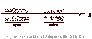
Case Mount Adaptor, BNC Part Number 4190-XX, and Cable Seal, BNC Part Number 10776-XX
The 4190-XX adaptor can be used for the attachment of junction boxes with 3/4 inch NPT threaded hubs. A particular version of this adaptor (4190-36) will allow the use of the 1/4 inch NPT 10076-XX cable seal (Figure 13 and Figure 11a).
High Pressure Feedthroughs, BNC Parts Numbers 20XXX and 2100X
High pressure feedthroughs consist of Bently Nevada 50 ohm or 95 ohm coaxial extension cable(s) enclosed at one point by a special fitting containing an epoxy seal. A dual coaxial cable system is shown in Figure 14.

Both single and dual cable high pressure feedthroughs are available (see data sheets L5019 and L5059 for ordering information).
High pressure feedthroughs provide passage of probe-to-Proximitior® extension cables through a machine case in situa-tions where a substantial pressure differential exists (up to 1000 psi).
When installing high pressure feedthroughs into a machine case, there are certain considerations to keep in mind, (An illustration of a typical split case machine showing proper gland seal location can be found in Figure 8).
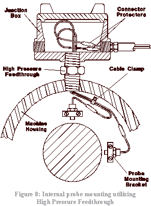
1. With the machine disassembled, try to select a location for the high pressure feedthrough on the portion of the case secured to the foundation. It might otherwise be difficult to install the high pressure feedthrough in the removed portion of the case and make an easy connection of probe lead(s) to extension cable(s). There would also be less likelihood of damage to the extension cables themselves during any subsequent disassembly.
2. A high pressure feed through should exit the machine case at a point above the residual oil level.
3. Certain environments both inside and outside the machine case may contain elements possible damaging to some types of “O-ring” seals. It is important to be aware of such elements. When ordering high pressure feed through, make sure the environment element(s) are specified.
Junction Box, BNC Part Number 03818016
The 03818016 junction box is primarily used to provide a location and protection for the probe-to-extension cable connection. Any one of five 3/4 inch NPT hubs could be used for attachment to a machine case via the 4190 adaptor; but to allow enough room for probe adjustment, the centrally located hub was selected (see previous “Internal Probe Mounting System” diagram, Figure 11a). Three (3) of the remaining hubs contain 3/4 inch NPT plugs and one (1) hub for extension cable exit through conduit.
The complete 03818016 junction box layout (Figure 15) depicts each individual component and respective part number.
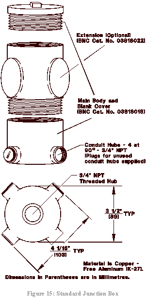
This junction box also provides protection for the external portion of an adjustable case mounted, long body probe. 4190 adaptors with the appropriate internal thread size will accommodate 0.190 inch, 0.300 inch, 5 mm and 8 mm probes with English thread size (see data sheet L5001 for the proper ordering information, Note: Metric thread available upon request). The optional extension (BNC Catalog Number 03818022) provides additional height to the junction box so that the long body probes and their leads can be properly protected and easily adjusted.
Bently Nevada also offers the 03818065 and 03818066 junction boxes as an alternative for those installations requiring minimum space. A system installation similar to that given earlier (“Internal Probe Mounting System”) is show in Figure 16. These junction boxes can also be used with the adjustable, case mounted type probe.
Note: When properly installed with explosion-proof fittings, the junction boxes 03818065, 03818066 and 03818016 are certified by CSA for use in the following classified hazardous areas; CLASS I, Group C, D; CLASS II, Groups E, F, G; CLASS III.
Relative Probe Housing Assembly
The 21000 Series relative probe housing assembly (Figure 17) provides a convenient means for through-the-case probe mounting. It consists of a proximity probe contained within an integral threaded adaptor/junction box housing. Also included are a jam nut, lock washer and “O-rings”.

Installation of 21000 Assembly
(Refer to Figure 17 for the following installation information).
1. Unscrew dome cover from housing, loosen sleeve jam nut, and unscrew the sleeve with locking washer and jam nut.
2. Do not remove probe from sleeve unless the probe is to be replaced. See “Probe Replacement” section for correct procedures.
3. Apply nonmetallic anti-seize thread compound to all 3/4 inch NPT threads.
4. Install housing (or housing with adaptor) into machine case.
5. Install conduit (or optional explosion-proof fittings and then conduit) to 3/4 inch 14 conduit connections in housing. (Install conduit hole plugs in any unused conduit hole). Install extension cable through conduit, but do not connect to probe cable at this time.
6. Carefully hand turn the sleeve (with probe, locking washer and jam nut) into the housing (see Figure 17). Allow the probe cable to turn with the sleeve to prevent cable damage. Do not allow probe tip to accumulate any thread compound or foreign conductive material during installation because signal error may result. Adjust gap in accordance with the preceding probe installation section.
7. Secure the sleeve in correct probe gap position with jam nut. Bend tabs of locking washer to secure nut.
8. Connect the probe cable to extension cable. Install a connector protector or the connectors can be wrapped with Teflon® tape, covered with shrinkable tubing or encapsulated the RTV or similar sealant that does not have an acetic acid base.
9. Install the dome cover to housing.
Axial Position or Thrust Position
Each machine configuration will usually dictate that one particular thrust probe installation system is more desirable than the other possible systems (i.e., internal mounting vs. External mounting; see typical illustrations as depicted in Figures 19a and 19b.
 Position")
 Position")
Regardless of the system choice, the installation hardware should allow proper probe location. As stated earlier in this note, the thrust probe(s) should be located within 300 mm (12 inches) or the thrust collar. However, there are equally important considerations related to the proper installation of thrust probes and related hardware:
1. The probe(s) must observe a surface that is perpendicular to the rotor axis and has a width equal to or greater than 2X the probe tip diameter. This is of particular importance if a thrust probe observes a step in the rotor rather than the end of the rotor or the thrust collar directly.
2. When setting the probe, the gap must be such that the available linear range of the transducer corresponds to the available position change (float zone) of the rotor plus some possible “wear range” on either surface of the thrust bearing (Figure 20). Ideally, the float zone should correspond exactly to the center of the transducer linear range, so that some thrust wear in either side of the bearing will still provide a probe gap within the linear range.

Note: The float zone width, measured mechanically when the machine is stopped (and cold), may not be the same width when the machine is running (and is hot).
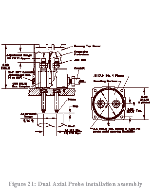
3. If two (2) probes in a dual voting arrangement are used for automatic trip service (voting between redundant transducers), at least one (1) probe must observe a surface integral to the rotor. The other probe may or may not be observing the same surface (API 670 requirement). A convenient means of providing redundant probes is the Bently Nevada 21022 dual axial probe installation assembly, It allows flexibility for side-by-side probe mounting at the end of the machine when it is feasible to do so (Figure 21).
Keyphasor ®
Keyphasor® installations closely resemble shaft relative radial vibration probe installations. In regard to specific considerations for Keyphasor® probe placement (see Figure 22.)

Eccentricity Position and Slowroll Bow Measurement
Internal or external probe mounting methods, as prescribed previously for shaft relative radial vibration measurement, can be implemented for either form of eccentricity measurement.
Required Tools for Installation
1. Wire Cutter.
2. Thermal wire stripper with temperature limit adjustment: The purpose of this tool is to allow removal of the Teflon outer jacket and inner conductor insulation without mechanical damage to either the coaxial cable braid or the inner conductor wires. While highly desirable, and utilized in Bently Nevada factory-installed connectors, it is not absolutely necessary to remove the Teflon with a thermal wire stripper. A normal wire stripping tool may be used as long as extreme care is taken to avoid damage to the braided outer shield and/or the stranded inner conductor.
3. Crimping tool: The crimping tool is a absolute necessity to proper installation of connectors. The appropriate ordering part number can be obtained from the Transducer Accessory data sheet, L5021.
4. Sharp knife.
5. Reasonably high quality wire stripper: Available from almost any electrical products supplier.
6. Dow-Corning 3140 RTV Sealant: This is used for environmental protection of the connector holes after the crimping operation is performed and for further environmental protection after two connectors are joined and wrapped with Teflon tape.
7. Flaring tools for 50 and 95 ohm cable: These are utilized for flaring the braided shield back from the inner conductor at approximately a 45 angle without damage to the braid. This is to allow the braid to be installed on the outside of the ferrule. While highly desirable, this item is not an absolute necessity as long as reasonable care is exercised in flaring the shield. The flaring operation should be performed very carefully with a pointed, but not overly sharp tool without separating the braid of the connector. If the braided configuration of the coaxial cable shield is destroyed by an improper flaring operation, it will alter the precise diameter required for proper mechanical connector/cable strength after the crimping operation is performed.