Voltage Drop Calculations – Electrical System Design
Voltage Ranges
The actual voltage present in any part of a power distribution system will deviate from
nominal due to voltage drop on the system. ANSI standard C84 specifies the allowable
tolerance for various nominal voltage levels. For low voltage system (<1,000V), the actual
service voltage must lie within ±5% of nominal for continuous operation. On medium voltage
system up to 35kV, the service voltage must lie within -2.5% and +5% for nominal for
continuous operation. Any voltage deviation beyond these tolerances must be corrected. On
high voltage transmission systems, the voltage range is generally the same as for medium
voltage systems.
Voltage Drop Defined


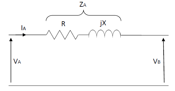
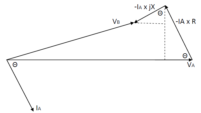
From the above figures, the voltage drop can be expressed as follows:
V drop = IA x (R cosΘ – X sinΘ)
For three system multiply the above equation by √3, and for single phase system, multiply the above equation by 2.
Three Phase Transformer Impedance
Transformer impedances are generally specified in percent based on the nameplate apparent power and voltage rating of the transformer.
RTR = [(%R) x (Secondary line Voltage)² / Transformer VA rating] /100
XTR = [(%X) x (Secondary line Voltage)² / Transformer VA rating] /100
If the transformer percent impedance %ZTR, and X/R ratio are given, transformer resistance and inductance can be determined as follows:
Θ = tan-1 (X/R),
% RTR = %ZTR x cosΘ, % XTR = %ZTR x sinΘ
Transformer Taps
The presence of taps on a transformer winding essentially means that the transformer turns ration is adjustable to the amount specified by the tap rating. As such, the output voltage of the transformer is adjustable by changing the tap setting. The transformer turns ratio can be defined as: a = VP/VS, for transformers with tapped windings, the rated high side or low side windings will vary depending on the tap setting. The actual voltage on the low voltage side under no load conditions is:
VS = Applied primary voltage x Rated secondary voltage/ Primary tap voltage
Voltage Drop Due to Motor Starting
Special consideration must be given to the voltage drop or flicker that occurs on a power system due to large motor starting. The locked rotor kVA of a motor during starting is several times the normal full load kVA. This large inrush current will cause a momentary dip in voltage as the motor comes up to speed.
Example: A 50hp, 460V, code letter G induction motor is to be started with full voltage applied from a 480Y/277V system whose equivalent impedance is 0.01 + j0.02 ohms/phase.
Assume a locked rotor power factor of 35% lagging. Calculate the percent voltage drop during starting using (a) the constant impedance and (b) the constant current representations.
Solution: (a) The locked rotor kVA/hp is between 5.6 and 6.3. For worst case voltage drop, a value of 6.3 will be used. The locked rotor kVA during starting is:
kVALR = 6.3kVA/hp x 50hp = 315kVA
The locked rotor current is: ILR = 315,000/ √3 x 460V = 395.4A
The active and reactive power during starting are:
P = 315kVA x 0.35 = 110.25kW
Q = 315kVA x (1-0.35) = 295.1kvar
The locked rotor resistance and reactance are determined as:
R = (1/3) x(110.25kW/ 395.4²) = 0.2351 ohm
X = (1/3) x(295.00kvar/ 395.4²) = 0.6292 ohm
The voltage drop at the motor terminals is determined by applying the voltage divider rule:
VM = 277 ˪0° x ((0.2352+j0.6292)/ (0.2352+j0.6292+0.01+j0.02))
VM = 268.1˪-0.2° V
%VDrop = ((277-268.1)/ 277) x 100% = 3.213%
(b) the constant current representation of the motor is determined by selecting the A phase line to neutral voltage as a reference. Therefore,
IM = 395.4˪-69.7° A
Using the approximate method, the voltage drop is:
VDrop = 395.4A (0.01 x cos(-69.7) – 0.02 x sin(-69.7)) = 8.8V
%VDrop = (8.8/ 277) x 100% = 3.173%
Voltage Drop Studies
The following general procedure represents the requirements for voltage drop study for single and three phase systems as designated.
Step 1. Determine all system impedance in ohms.
Step 2. Determine the load supplied at the end of each segment or portion of the system.
Step 3. Determine the load current magnitude and phase angle using the load data from step 2.
Step 4. Calculate the percent voltage drop along each segment of the circuit, starting at the source.
Step 5. Add the percent voltage drops along each segment, starting at the source, to the point of interest.
Single Phase System

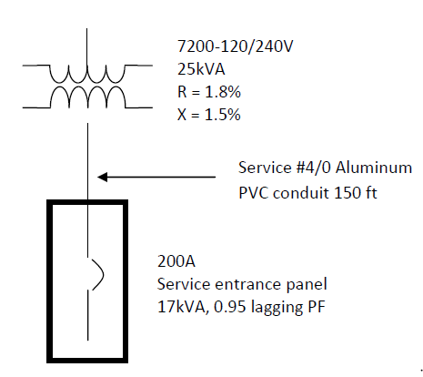
Determine the percent voltage drop at the service panel for the system shown in figure 4.3.
The total load is 17kVA at 0.95 lagging power factor.
Step 1. Determine all system impedance in ohms.
Transformer R = (1/100)*((1.8%)*(240V)2/ 25,000VA) = 0.041472 ohm
Transformer X = (1/100)*((1.5%)*(240V)2/ 25,000VA) = 0.03456 ohm
Cable R = 2 * ((0.1 ohm/1000 ft)/1000)*150 ft = 0.03 ohm
Cable X = 2 * ((0.041 ohm/1000 ft)/1000)*150 ft = 0.0123 ohm
Step 2. Determine load supplied at the end of each segment or portion of the system.
The loading is given as 17kVA at 0.95 lagging power factor.
Step 3. Determine the load current magnitude and phase angle using the load data from step 2.
I = 17,000VA/ 240V = 70.83A
Θ = cos-1(0.95) = -18.2°
Step 4. Calculate the percent voltage drop along each segment of the circuit, starting at the source.
The approximate method is used.
Transformer:
Vdrop = 70.83A x (0.041472 ohm x cos (-18.2) – 0.03456 ohm x sin (-18.2)) = 3.56V
%Vdrop = (3.56V/240V0 x 100% = 1.48%
Cable:
Vdrop = 70.83A x (0.03 ohm x cos (-18.2) – 0.0123 ohm x sin (-18.2)) = 2.29V
%Vdrop = (2.29V/240V0 x 100% = 0.95%
Note that the percent voltage drop were calculated based on the line to line voltage of 240V.
Step 5. Add the percent voltage drops along each segment, starting at the source to the point of interest.
Transformer 1.48%
Cable 0.95%
_____
Total 2.43%
Three Phase System
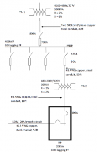
Determine the percent voltage drop at MDP, panel RP, and at the end of the single phase branch circuit for the system shown in figure 4.4. The load on the single phase branch circuit is 12A at 0.85 lagging power factor. The total load on panel RP has been determined to be 20kVA at 0.85 lagging power factor. The loading on the MDP is 400kVA at 0.9 lagging power factor.
Step 1. Determine all system impedance in ohms.
Transformer TR1: R = ((2%)(480V)2/500,000VA)(1/100) = 0.009216 ohm
X = ((6%)(480V)2/500,000VA)(1/100) = 0.027648 ohm
Note that transformer TR1 impedance are referred to the 480V side of the transformer.
Parelle 500kcmil cable: R = (0.029ohm/1,000ft/1,000)(30ft) = 0.00087 ohm
X = (0.048ohm/1,000ft/1,000)(30ft) = 0.00144 ohm
Note that the cable impedance is for one conductor of the parallel group.
#8 AWG cable: R = (0.78ohm/1,000ft/1,000)(50ft) = 0.039 ohm
X = (0.065ohm/1,000ft/1,000)(50ft) = 0.00325 ohm
Transformer TR2: R = ((2%)(208V)2/30,000VA)(1/100) = 0.02884 ohm
X = ((2%)(208V)2/30,000VA)(1/100) = 0.02884 ohm
Note that transformer TR2 impedances are referred to the 208V side of the transformer.
#3 AWG cable: R = (0.25ohm/1,000ft/1,000)(10ft) = 0.0025 ohm
X = (0.059ohm/1,000ft/1,000)(10ft) = 0.00059 ohm
#12 AWG cable: R = (2.0ohm/1,000ft/1,000)(50ft) = 0.2 ohm
X = (0.068ohm/1,000ft/1,000)(50ft) = 0.0068 ohm

Step 2. Determine load supplied at the end of each segment or portion of the system.
he loading on transformer TR1, the parallel 500kcmil service cable, and the MDP is 400kVA at 0.9 lagging power factor. The loading on the 50ft #8 AWG feeder to transformer TR2, transformer TR2, and the 10ft #3 AWG feeder to panel RP is 20kVA at 0.85 lagging power factor. Last, the loading on the 50ft #12 AWG branch circuit is 12A at 0.85 lagging power factor.
Step 3. Determine the load current magnitude and phase angle using the load data from step 2.
To determine the corresponding line current magnitude, the voltage at which the circuit operates must be determined. Since the impedance of transformer TR1 were determined on the 480V side, the load current will be calculated at 480V. Likewise, the parallel 500kcmil service conductors and the 50ft #8 AWG feeder to transformer TR2 operate at 480V. The magnitude and phase angel of the load current through transformer TR1 is:
I = (400,000VA/√3 480V) = 481.1A
Θ = – cos-1(0.9) = -25.84°
The current in one conductor of the parallel 500kcmil service conductors is the total current of 481.1A divided by the number of conductors in parallel per phase. Thus, for two parallel conductors per phase, 240.6A per conductor will flow.
The current through the 50ft #8 AWG feeder to transformer TR2 is based on 20kVA at 480V, 0.85 lagging power factor:
I = (20,000VA/√3 480V) = 24.1A
Θ = – cos-1(0.85) = -31.8°
Since the impedance of transformer TR2 were determined on the 208V side, the load current will be calculated at 208V. Likewise, the 10ft #3 AWG feeder from transformer TR2 to panel RP operates at 208V. The magnitude and phase angle of load current through transformer TR2 is:
I = (20,000VA/√3 208V) = 55.5A
Θ = – cos-1(0.85) = -31.8°
The current through the single phase branch circuit was given in the problem statement as 12A. The phase angle of this current is -31.8°, corresponding to 0.85 lagging power factor.
The load currents are summarized as Transformer
TR1: I = 481.1 ˪ -25.84° A
500kcmil Service: I = 240.6 ˪ -25.84° A per phase
#8 AWG Feeder; I = 24.1 ˪ -31.8° A
Transformer TR2: I = 55.5 ˪ -31.8° A
#3 AWG Feeder: I = 55.5 ˪ -31.8° A
#12 AWG Feeder: I = 12 ˪ -31.8° A
Step 4. Calculate the percent voltage drop along each segment of the circuit, starting at the source.
The approximate method is used.
Transformer TR1:
Vdrop = 481.1A x ((0.009216Ω x cos -25.84) – (0.027648Ω x sin -25.84)) = 9.79V
% Vdrop = 9.79V x 100% / 277V = 3.53%
500 kcmil service cable:
Vdrop = 240.6A x ((0.00087Ω x cos -25.84) – (0.00144Ω x sin -25.84)) = 0.34V
% Vdrop = 0.34V x 100% / 277V = 0.12%
#8 AWG feeder:
Vdrop = 24.1A x ((0.039Ω x cos -31.8) – (0.00325Ω x sin -31.8)) = 0.84V
% Vdrop = 0.84V x 100% / 277V = 0.3%
Transformer TR2:
Vdrop = 55.5A x ((0.02884Ω x cos -31.8) – (0.02884Ω x sin -31.8)) = 2.2V
% Vdrop = 2.2V x 100% / 277V = 1.84%
Note that the percent voltage drop is now calculated with respect to 120V line to neutral rather than 277V.
#3 AWG feeder:
Vdrop = 55.5A x ((0.0025Ω x cos -31.8) – (0.00059Ω x sin -31.8)) = 0.14V
% Vdrop = 0.14V x 100% / 120V = 0.11%
#12 AWG BRANCH:
Vdrop = 12.0A x ((0.2Ω x cos -31.8) – (0.0068Ω x sin -31.8)) = 2.1V
% Vdrop = 2.1V x 100% / 120V = 1.74%
Step 5. Add the percent voltage drops along each segment, starting at the source, to the point of interest.
The total voltage drop at the MDP is:
TR1: 3.53%
500 kcmil: 0.12%
_____________
Total: 3.65%
The voltage drop at panel RP is:
Drop at MDP: 3.65%
#8 AWG feeder: 0.30%
TR2: 1.84%
#3 AWG feeder: 0.11%
_____________
Total: 5.90%
The voltage drop at the end of the #12 AWG branch circuit is:
Drop at RP: 5.90%
#12 AWG branch: 1.74%
_____________
Total: 7.64%