- SCOPE
- REFERENCES
- GENERAL
- APPLICATION OF WELDED JOINTS AND SYMBOLS
- DEFINITIONS OF TERMS AND SYMBOLS
FIGURES
- Examples of Vessel Welds
- Examples of Joints in Sheet Metal – 10 to 18 Gauge
- Examples of Pipe and Pipe Connection Welds
- Examples of Welded Bosses
- Examples of Welds for Mechanical Equipment
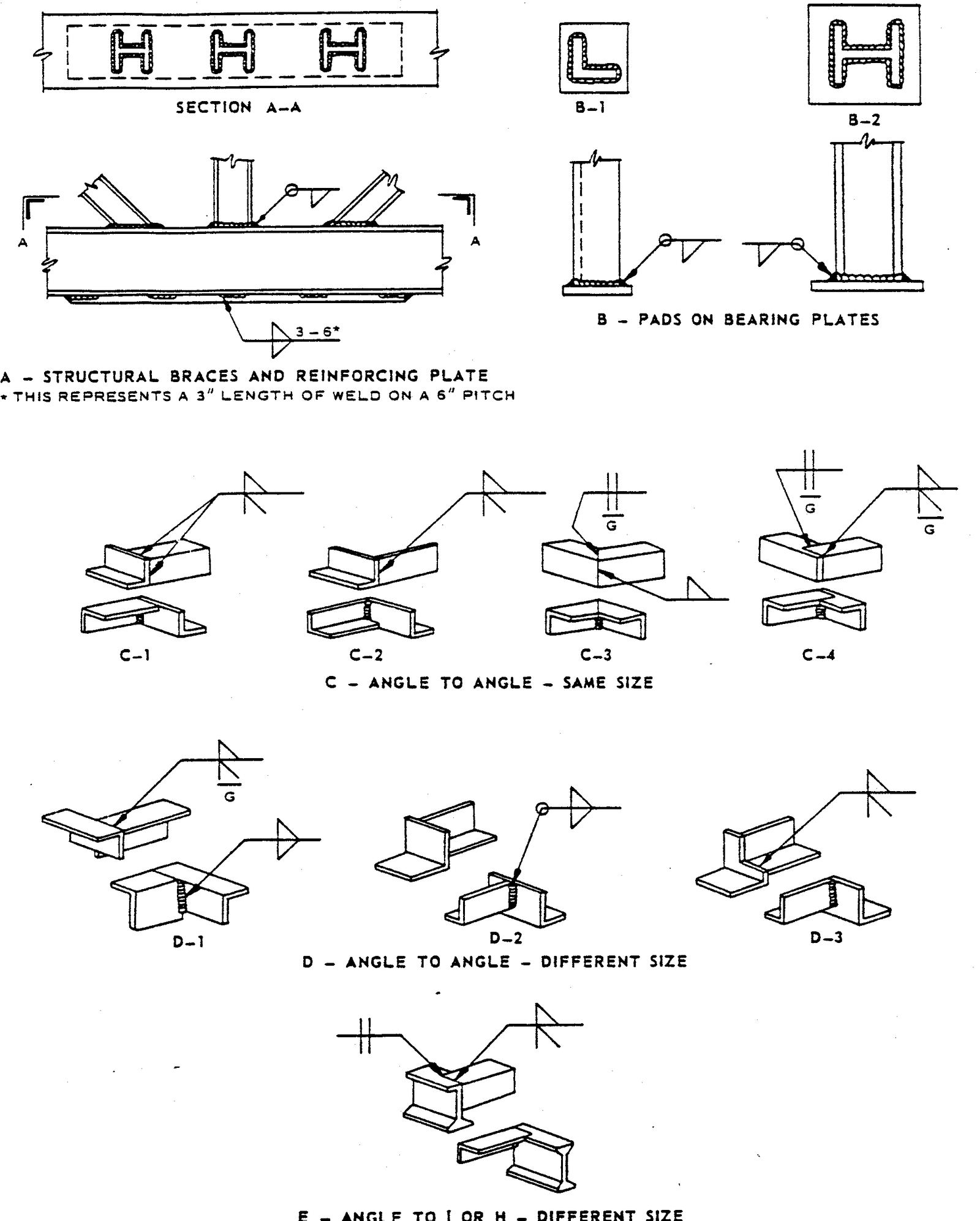
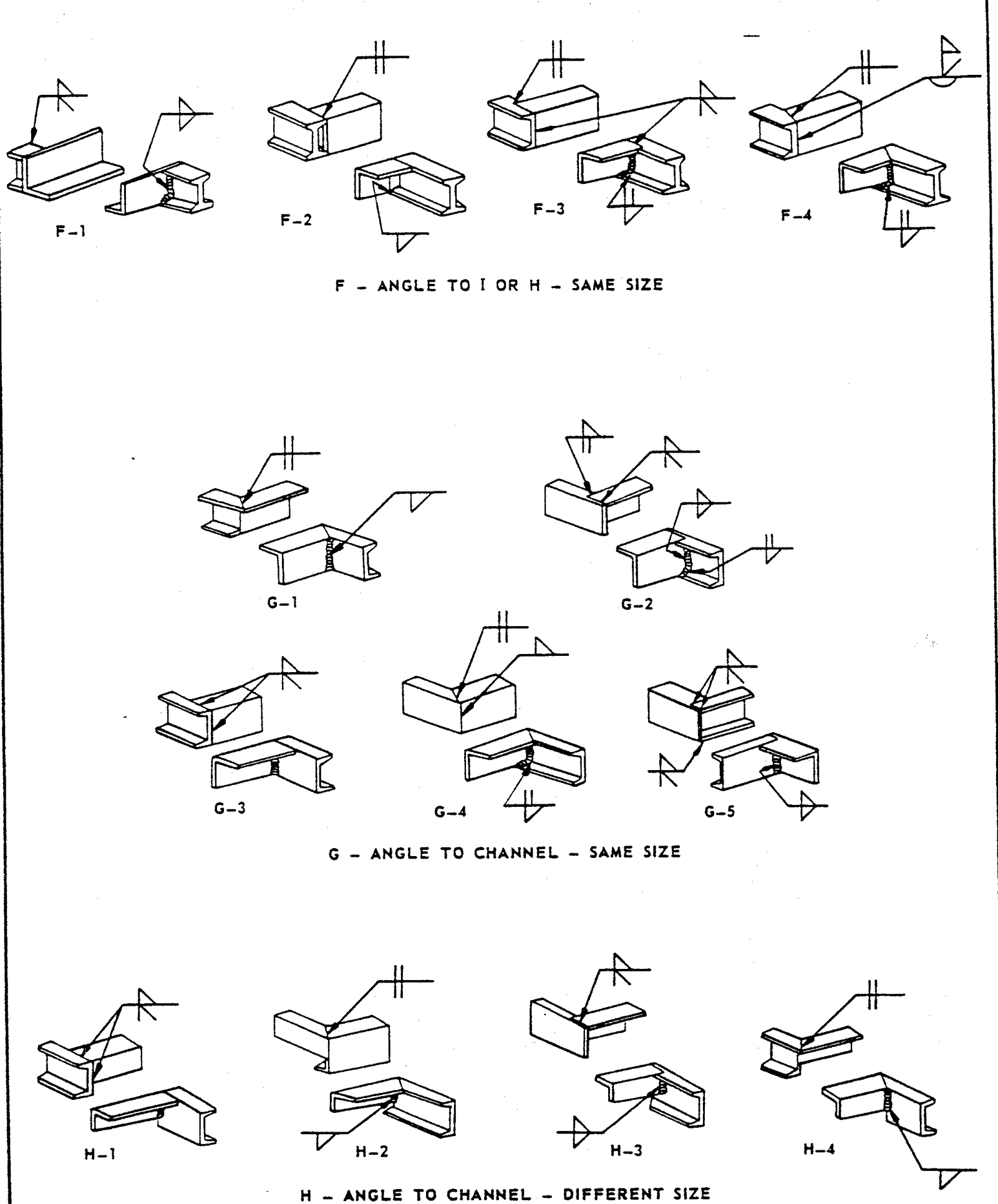
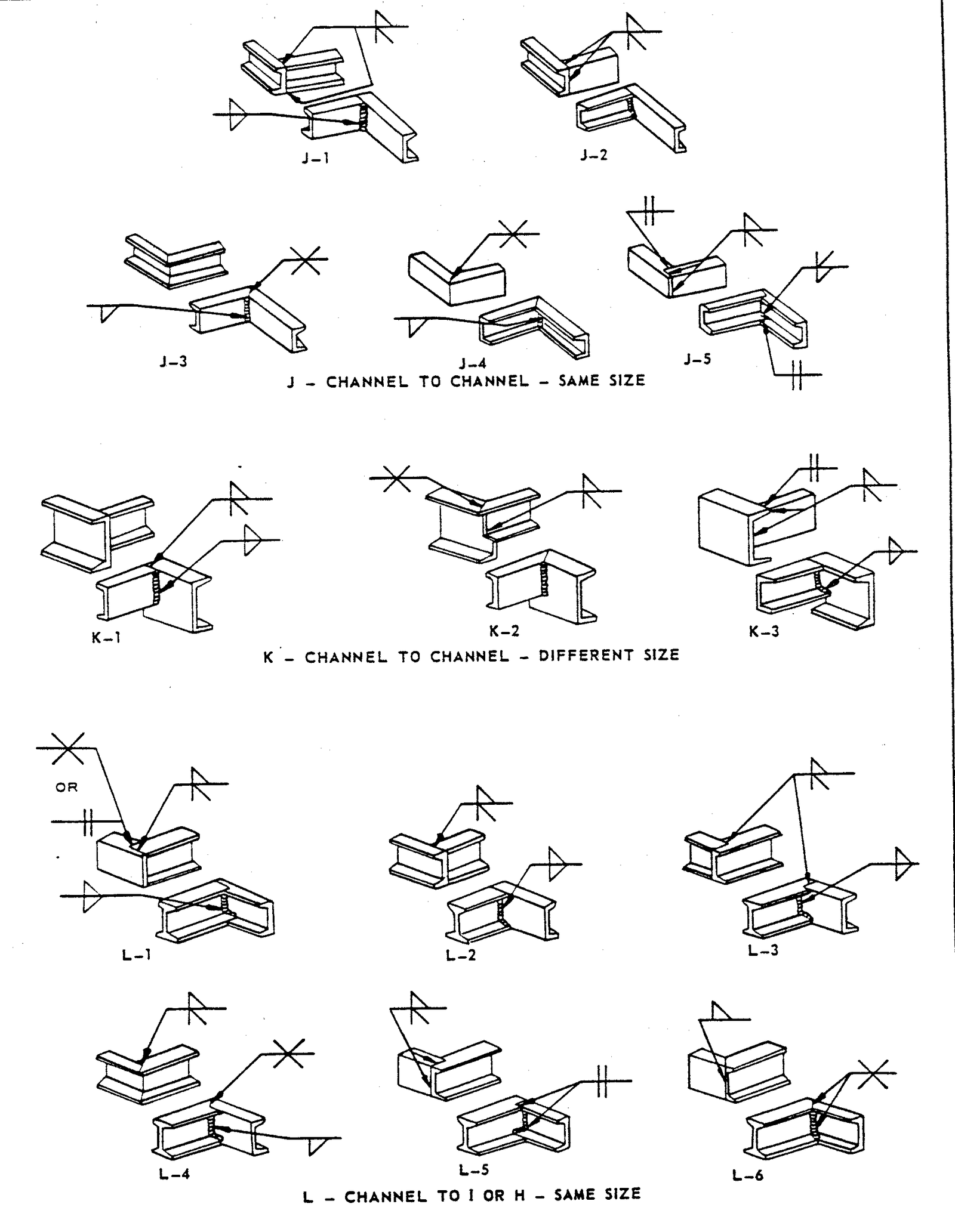
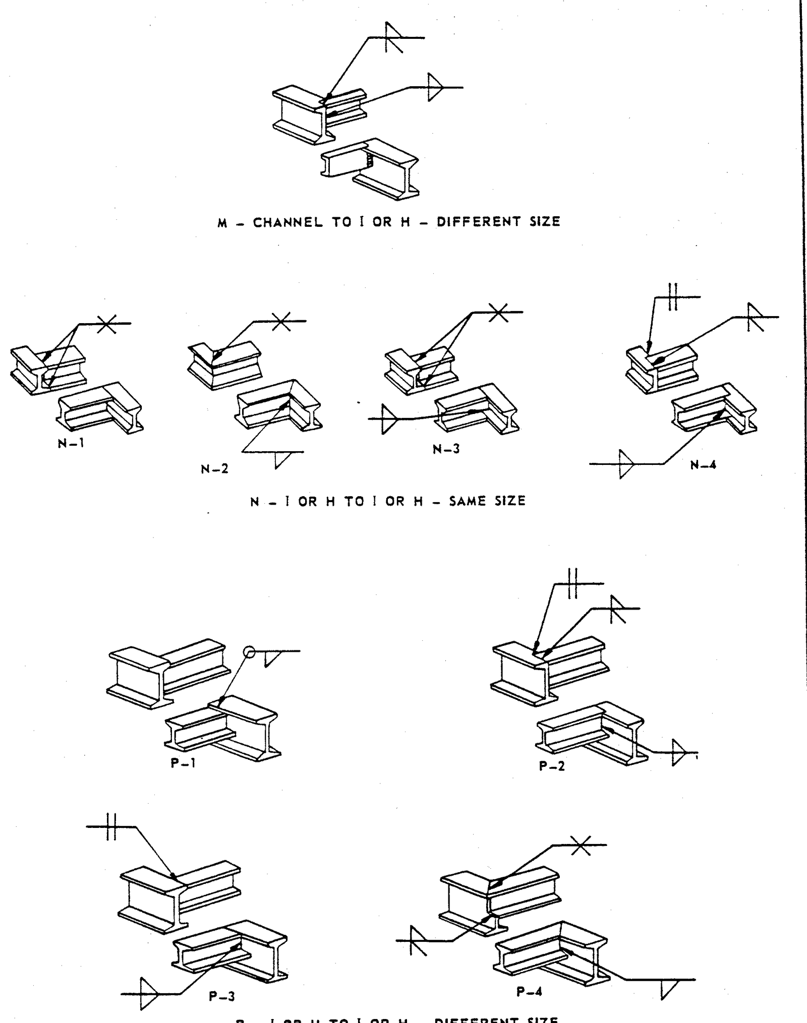
- Examples of Structural Welds
TABLE I Referenced Weld Types
Welded Joints and Applied Symbols
1. Scope
This Article describes the acceptable types of welded joints for both pressure and non pressure parts, and illustrates the symbols to be used to identify the welds.
2. References
3. General
3.1 This standard does not limit the types of joints illustrated herein, nor to the circumstances for their use. Examples in Figures 1 – 6 are to be used as a design guide and as a reference for welded fabrication.
3.2 Welding symbols shall be in accordance with ANSI/AWS A2.4. Fabricator’s drawings shall show the appropriate welding symbol for the particular joint, and the size of weld and the filler metal that is to be used.
3.3 Any deviation from the methods shown shall be approved by SABIC prior to the start of fabrication.
4. Application of Welded Joints and Symbols
4.1 For welds applicable to branch connections, refer to ASME B31.3.
5. Definitions of Terms and Symbols
5.1 To clearly define a weld, it is necessary to indicate the basic type of weld (square, bevel, fillet, plug, or slot), the plate preparation, and size into which the weld is to be deposited.
5.2 It is necessary to provide supplementary information as to whether the weld is to be ground or ground flush or convex and, when required, to give the finish.
TABLE I – Referenced Weld Types
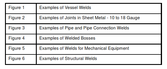
FIGURE 1 – Examples of Vessel Welds
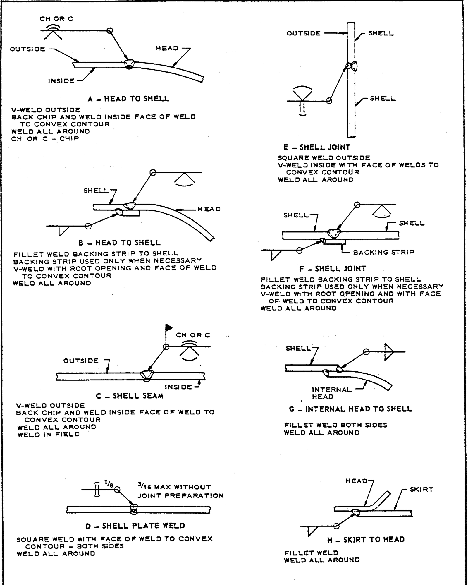
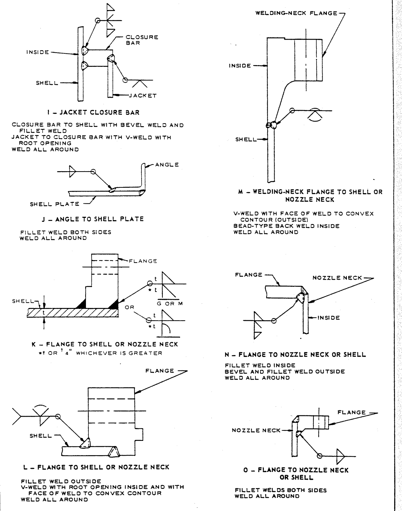
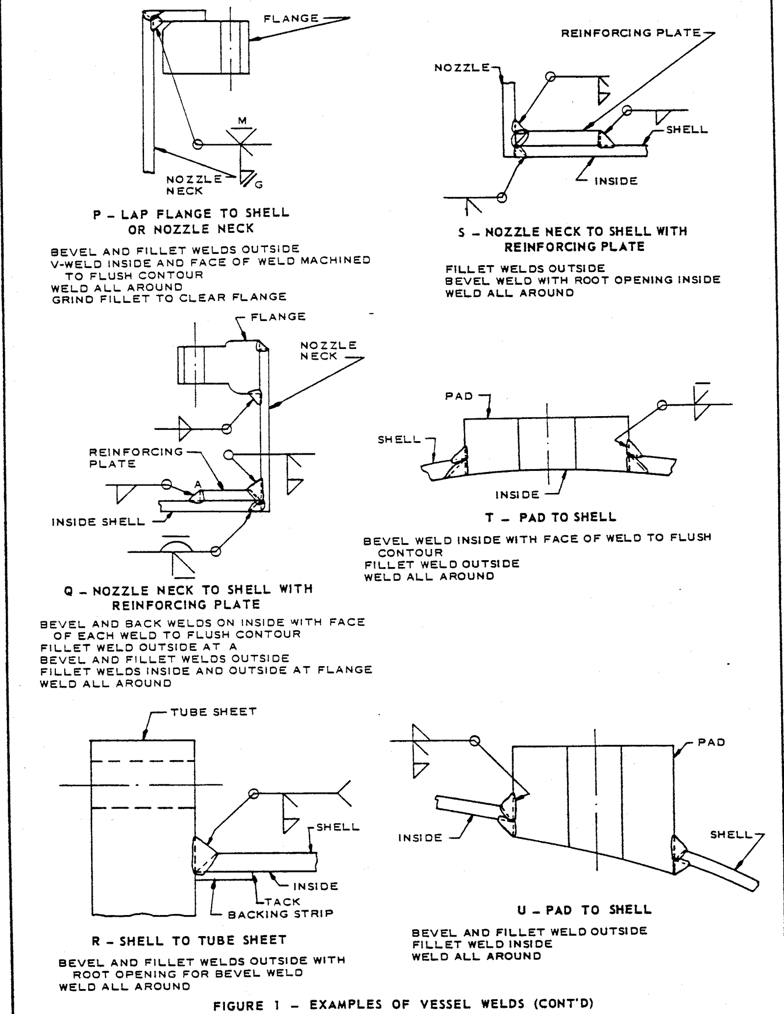
FIGURE 2 – Examples of Joints in Sheet Metal – 10 to 18 Gauge
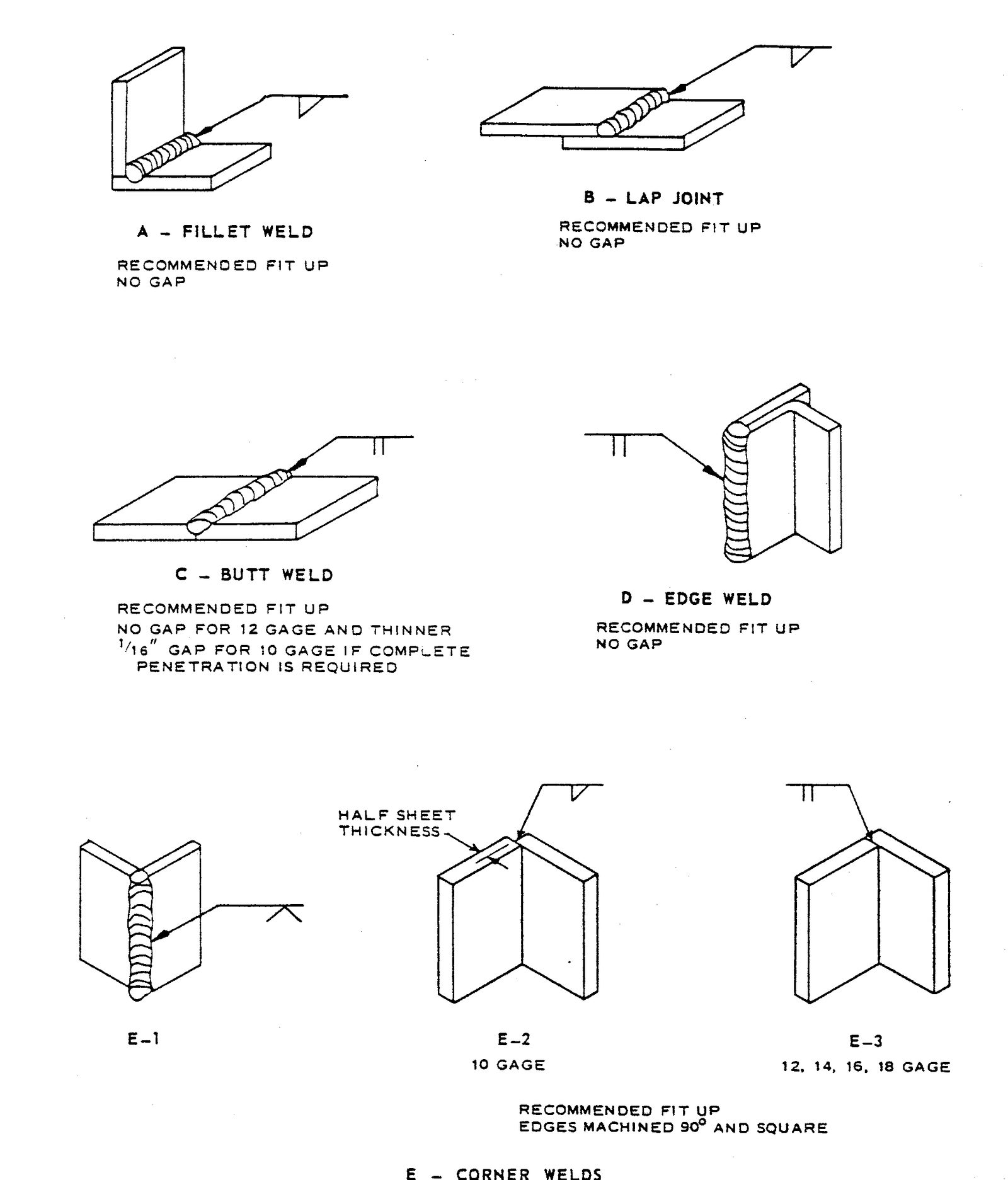
FIGURE 3 – Examples of Pipe and Pipe Connection Welds
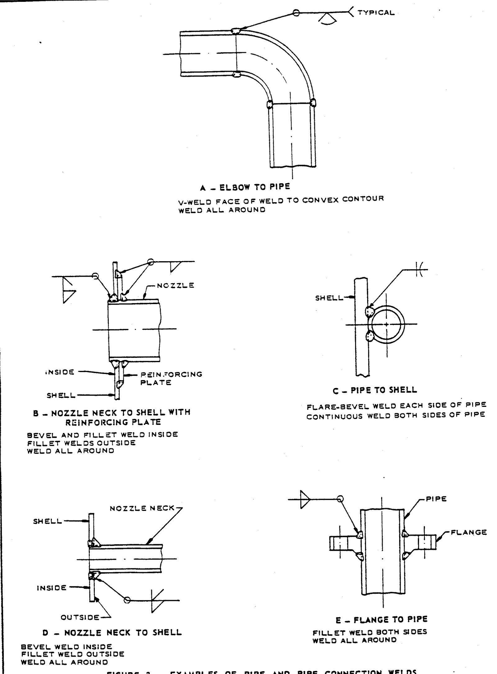
FIGURE 4 – Examples of Welded Bosses
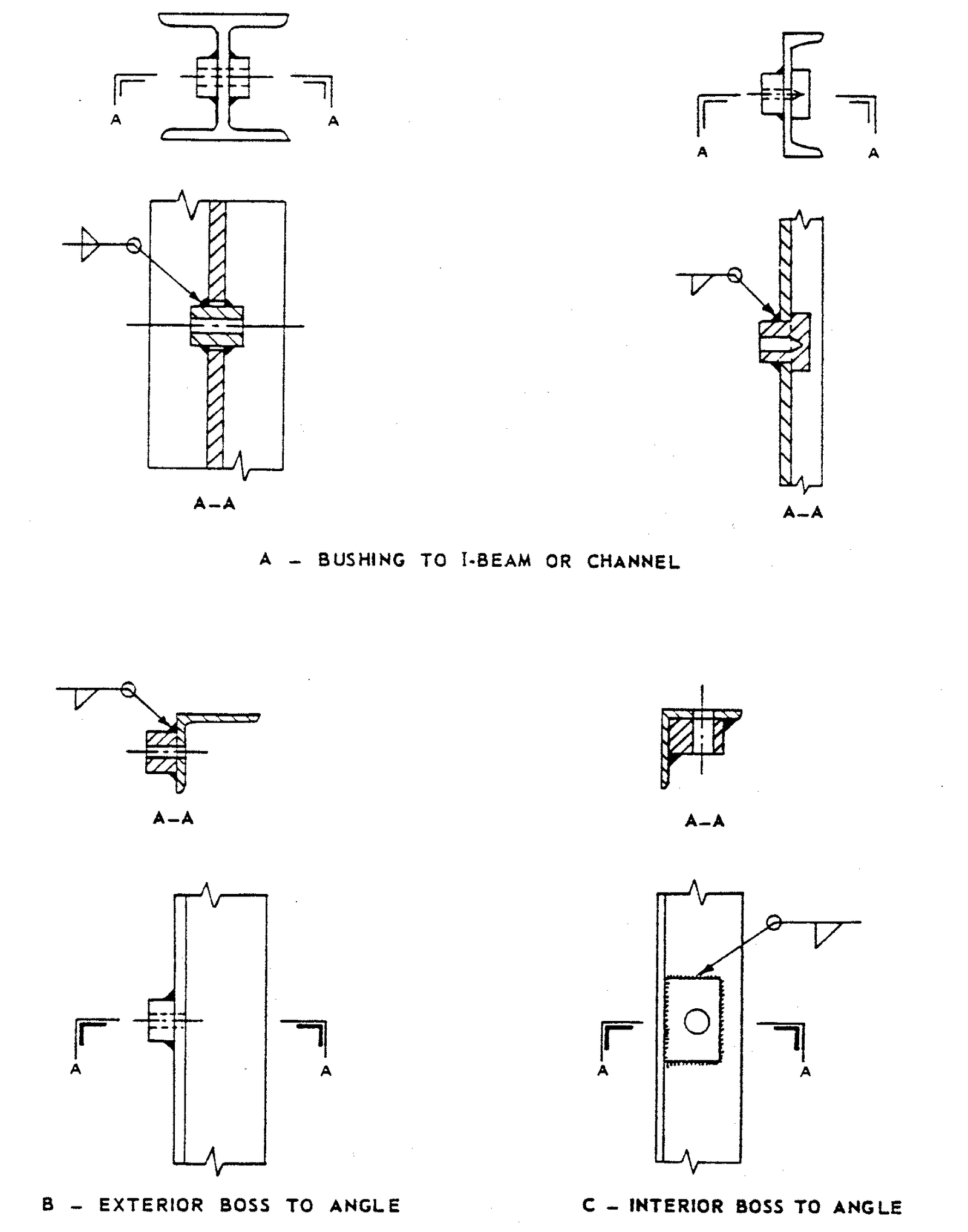
FIGURE 5 – Examples of Welds for Mechanical Equipment
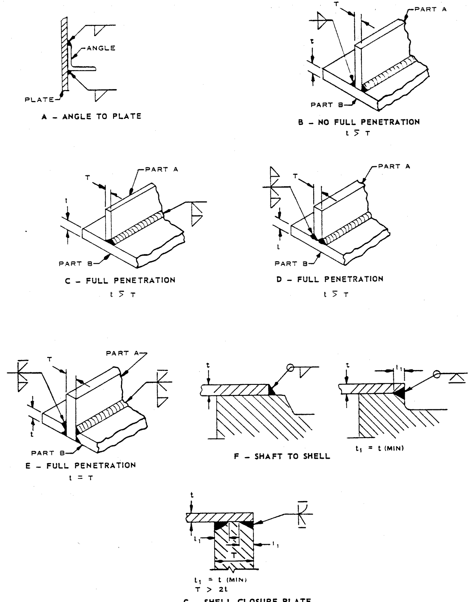
FIGURE 6 – Examples of Structural Welds
