- SCOPE
- REFERENCES
- GENERAL
- SAFETY
- WORKMANSHIP
- Welding
- Assembly Methods
- INSPECTION AND TESTING
FIGURE
- Core Pipe to Flange Arrangements
- Jacket to Flange Arrangements
- Flange Dissimilar to Core and Faces
- Jacket Termination Before Flange(Similar Materials)
- Jacket Termination Before Flange (Dissimilar Materials)
- Alternate Jacket Terminations
- Jacket Branch Connection
- Branch Connection to Core Pipe
- Block or Rod Spacers
- Reducers for Polymer Piping
Welding of Jacket Piping
1. Scope
This article is about information on design, selection, and assembly arrangements for the welding of jacketed piping.
2. References
Reference is made in this standard to the following documents.
3. General
3.1 This standard does not limit construction to that shown or suggested herein, recognizing that special design and construction are often necessary to suit specific problems. This standard addresses common cases of design and construction, and any deviation shall have the approval of appropriate authority.
3.2 The fabrication requirements of jacketed piping and materials of construction shall be specified either on the drawing or in the purchase order.
3.3 Requirements vary considerably for jacketed piping due to differences in application. For this reason, many alternate details are provided. It is the responsibility of the designer calling for the use of this standard to designate the specific weld joints required.
4. Safety
Safe practices prescribed in SES W02-F01 shall be followed on plant sites.
5. Workmanship
5.1 Welding
5.1.1 All welders shall be qualified in accordance with SES W11-F01 to weld on the materials of construction specified.
5.1.2 For the type and method of welding the specified materials of construction, refer to the appropriate specification.
5.1.3 Welded joints in core pipes and at flanges shall be kept to an absolute minimum. Smooth bores are often required for polymer piping because cracks, pits, ridges, and valleys can harbor polymer that degrades and wipes streaks into the finished product. Specify the limit of such imperfections at the bore on the drawing.
5.1.3.1 Bend piping in polymer systems to eliminate welds whenever possible; however, some fabrications require fittings. When fittings are used, match the bore diameters within tolerances specified on the drawings, Reducers shall be of the continuous taper type as shown on Figure 10A, unless otherwise specified. Any interruption in the core pipe shall be of the concentric nature.
5.1.3.2 When welds are accessible only from the outside of the core pipe, take some means to prevent excessive protrusion of weld material into the core pipe. Determine the amount of protrusion allowable from process experience and design drawing. The methods that can be used to limit the protrusion are: (a) machine a 1.6 mm (1/16 in) land on the butt ends of the pipe and use a GTAW process on the first pass without the addition of any filler material. Succeeding passes may be made with either the GMAW, GTAW or the SMAW process, with filler material. (b) gas backup technique on stainless steel core as per SW30W.
5.1.4 In order to minimize the possibility of leaks and for maximum economy, keep welds in the jacket pipe to a minimum. Where jackets require welding from the outside, or shall split for installation over core, welds shall be of the full-penetration type. The root pass of full-penetration type welds shall be GTAW to avoid spattering or burning the core pipe.
5.1.5 Information on welding symbols and their use is in SES W01-F03 and W01-F04.
5.2 Assembly Methods
5.2.1 Core Pipe to Flange
5.2.1.1 Flanges shall be welded to the core pipe as shown on Figure 1A or 1B when slip-on flanges are used.
5.2.1.2 Where socket-type flanges are required, attachment shall be made in accordance with Figure 1D (not recommended for polymer systems because of voids).
5.2.1.3 Figures 3A, 3B, and 3C illustrate attachment of flange to core when similar metals are used. Figure 3D illustrates attachment of flange to core when dissimilar metals are used, for example, carbon steel backup flange with stainless steel core pipe.
5.2.1.4 Where slip-on flanges are to be welded to the core pipe for polymer systems, the flange shall be face welded first and back welded, then the face milled or machined back to a 90-degree face, and the bore refinished as shown on Figure 1E.
5.2.2 Spacers
5.2.2.1. The prime function of spacers is to support the core piping and only enough spacers shall be installed to accomplish this requirement. Allow the core piping to move as freely as possible. These spacers shall be either of the block or rod type, depending upon the space between core and jacket.
Block-type spacers shall be no closer than 152.4 mm (6 in) to the tangent line of the area to be bent. Grind all edges and sharp corners to a radius. Weld spacers to the core pipe of the same basic material as the core pipe and located approximately 120 apart around the pipe circumference. See Figure 9. Never use galvanized or zinc bearing (red pencil lead) materials when stainless steel core or jacket is involved.
5.2.2.2 The recommended clearance between spacers and jacket, under normal conditions, is 1.6 mm (1/16 in) after fabrication. When excess expansion or pipe movement is involved, additional clearance or a change in spacer location may be necessary. Refer to Figure 9.
5.2.3 Jacket to Flange
5.2.3.1 Figure 2 indicates jacket-to-flange connections. Each connection of this kind shall be thoroughly investigated to determine the flange type and if machining is necessary on the flange. The flange type shall be as recommended in the specification. No machining shall be performed on a flange until it has been established that the resultant configuration does not reduce the pressure rating of the flange below the design pressure of the system. Standard unbored, high-hub blind flanges are excellent for this application.
5.2.3.2 The configuration shown on Figure 2A shall be used for core pipe internal pressures up to 2069 kPa (300 psi). Figure 2B is suitable for core pipe internal pressures over 2069 kPa (300 psi). Figures 2A and 2B arrangements are suitable for core and jacket of different materials provided the flange is the same basic material as the core.
5.2.3.3 Slide the bulk of the jacket pipe over the core pipe and spacers, before the flanges are welded to the core pipe. In this manner, only a short piece of jacket pipe will have to be split longitudinally to make the final closure of the jacket.
5.2.4 Jacket to Core Pipe
5.2.4.1 Where process requirements permit (where temperature of the core pipe is not critical and it is not necessary to jacket the core pipe up the flange), a more economical jacket closure can be made as shown on Figures 4, 5, and 6. For Figures 4 and 5, swaging of carbon steel by a suitable machine is limited to ERW pipe.
5.2.4.2 The arrangements on Figures 5 and 6 cost more than Figure 4, and are used when core and jacket are dissimilar. Figure 4 can be used when the core pipe is stainless steel or nickel alloy and has a wall at least 4.8 mm (3/16 in) thick, or 3.2 mm (1/8 in) thick if the alloy is used for product cleanliness rather than corrosion resistance.
5.2.5 Core Pipe Branch Connections
5.2.5.1 Keep branch connections in the core pipe to a minimum because of their initial high cost and possibility of concealed leaks. Figure 8A shows a branch connection for use with a core and jacket with dissimilar materials, where parts have large differences in wall thickness, where the branch needs to be heated, or where differential expansion between jacket and core pipe is excessive. Large variations in expansion of core pipe and jacket pipe may be the result of temperature difference or materials of dissimilar coefficients of expansion.
5.2.5.2 Use designs similar to Figures 8B, 8C, and 8D where differential expansion between core pipe and jacket is negligible and the materials are compatible or no jacket is required on the branch.
a. Figure 8B illustrates the condition wherein a pipe connection is welded to the core pipe before the jacket is installed. In this case, the jacket is split to allow for installation over the core pipe and around the branch connecti
b. Figures 8C and 8D illustrate the condition wherein the jacket is installed over the core pipe before the branch connection is welded to the core. In both of these cases, holes large enough to permit installation and welding of branch connection to core pipe are made in the jacket. Following the attachment of the branch connection to the core, the hole in the jacket is sealed, either as shown on Figure 8C with a new piece (same material as jacket) cut from compatible material or as shown on Figure 8D using the piece originally removed from jacket when cutting the jacket openi
c. Tie-ins to the core pipe (pressure taps, thermocouple, drains or sample taps) shall be made as close to a flange as possible to aid in the prevention of fatiguing the branch pi
5.2.6 Jacket Branch Connection. The recommended application of branch connections on the jacket is shown on Figure 7.
6. Inspection and Testing
6.1 The amount and type of inspection required depends upon the service conditions and hazards to personnel and property. It is the responsibility of the originator to define the inspection requirements. Inspection shall be in accordance with applicable code(s).
6.2 Core piping shall be tested before completion of the jacket.
FIGURE 1 – Core Pipe to Flange Arrangements

FIGURE 2 – Jacket to Flange Arrangements
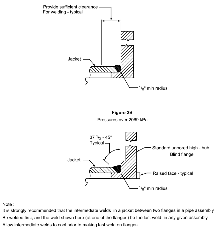
FIGURE 3 – Flange Dissimilar to Core and Faces
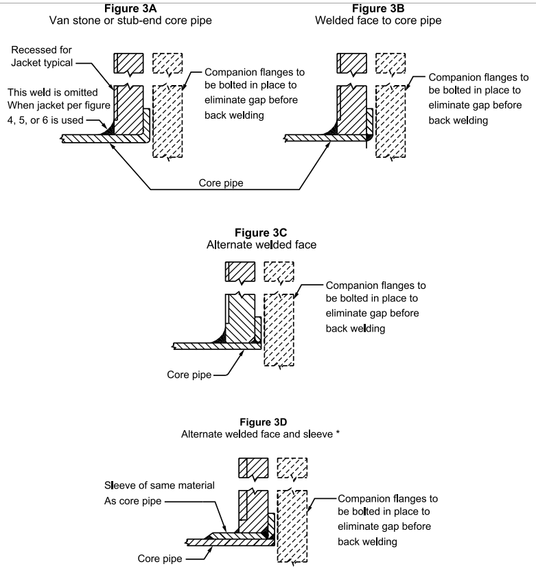
FIGURE 4 – Jacket Termination Before Flange*
Similar Materials

FIGURE 6 – Alternate Jacket Terminations

FIGURE 7 – Jacket Branch Connection

FIGURE 8 – Branch Connection to Core Pipe

FIGURE 9 – Block or Rod Spacers
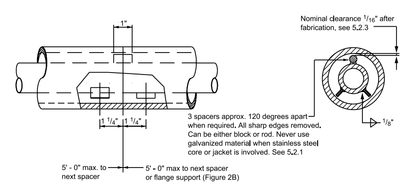
FIGURE 10 – Reducers for Polymer Piping
