- SCOPE
- REFERENCES
- SAFETY
- MATERIALS
- CLEANING AND STORAGE
- WELDING TECHNIQUE
- INSPECTION AND TESTING
- REPAIR AND FIELD WELDING
- QUALIFICATION PROCEDURE
FIGURES
- Permissible Joint Tolerances
- 1A. Square Butt Gap
- 1B. Flanged Butt Gap
- 1C. Square Butt Mismatch
- 1D. Flanged Butt Mismatch
- 1E. Heat Sink, Square Butt
- 1F. Heat Sink, Flanged Butt
- Flange Heights for Edge Flange Welds
- Tolerance for Edge Joints in Foil and Sheet
- 3A. Gap
- 3B. Mismatch
- Butt Welding Technique for Tantalum Tubing
- 4A. Tubing Fit-Up
- 4B. Starting Weld
- 4C. Completing Weld
- Flange Facing Welding Procedure for Tantalum Lined Pipe
- 5A. Flange Facing Prefabrication
- 5B. Starting Weld on Liner-Facing Assembly
- 5C. Weld in Progress
- Suggested Bend Test for Tantalum Welder Qualification Testing
- Gas Shield and Jig for Small Tubing
TABLE
- Tolerances for Butt Joints in Thin Materials
- Flange Heights for Edge Flange Welds
APPENDIX
- Flare V Groove Square. QW-482 Format for Welding Procedure Specification (WPS)
- Flare V Groove Square. 9-T-1. QW-483 Format for Procedure Qualification Record (PQR)
- Flare V Groove Square. 9-T-2. QW-483 Format for Procedure Qualification Record (PQR)
Welding Tantalum Materials by GTAW Process
1. Scope
This article is about requirements for joining tantalum materials of 0.5 to 6.4 mm (0.020 to 1/4 in) thickness in all positions by the gas tungsten arc welding (GTAW) process.
2. References
Reference is made in this standard to the following documents.
American Society for Testing and Materials (ASTM)
B364 Specification for Tantalum and Tantalum Alloy Ingots
B365 Specification for Tantalum and Tantalum Alloy Rods and Wire
B521 Specification for Tantalum and Tantalum Alloy Seamless and Welded Tube
American Welding Society (AWS)
A5.12 Specification for Tungsten and Tungsten Alloy Electrodes for Arc Welding and Cutting
3. Safety
Safe practices prescribed in SES W02-F01 shall be followed on plant sites.
4. Materials
4.1 Sheet metal shall be pure unalloyed tantalum in compliance with ASTM B364. The purchase order shall specify if material supplied is produced by double melting technique.
4.2 Filler metal shall be pure unalloyed tantalum in compliance with ASTM B365, produced by a double melting technique.
4.3 Tubing shall be tantalum or tantalum alloy in compliance with ASTM B521, available as seamless or welded, and produced by a double-melting technique.
4.4 Shielding gas shall be 99.995 percent pure argon.
4.5 Electrode shall be in compliance with AWS A5.12, Classification EW Th-1, or Th-2.
5. Cleaning and Storage
5.1 Absolute cleanliness is essential for good tantalum welding. Cleanliness prevents porosity, microfissuring, and cracking of the joint or heat-affected zone or both.
5.2 The degree and method of cleaning depends upon the amount and location of contaminants. Heat generated in the welding process is conducted a considerable distance from the point of welding. Should organic compounds be present, these materials will vaporize and cause contamination. Tantalum is reactive at temperatures exceeding 316 C (600 F). Consequently, clean tubing and pipe internally as well as externally.
5.3 Do not use caustic cleaning materials.
5.4 Solvent Cleaning. Regardless of the cleaning technique selected below, the first step shall be a thorough rinse in a volatile environmentally friendly solvent. Remove all traces of oil film and handling stains. Use rubber, lint-free cotton, or nylon gloves when handling the part from the rinse. Lint-free cloths may be used for wiping.
5.5 Mechanical Abrasion. Abrade all surfaces, including edges that will be subject to welding heat, with clean aluminum oxide to remove the naturally occurring oxide film. Water cooling may be necessary when power abrading. Use nylon or lint-free cotton gloves during this cleaning operation. Inspect gloves frequently for cleanliness. (Note: A powered abrasive flapper is a suitable abrasive tool.) Subsequent to this cleaning operation, make a second solvent rinse; immediately place the part in the welding chamber, and start an argon purge.
5.6 Chemical Cleaning. Under certain conditions, acid cleaning (pickling) may be required. Where the tantalum surfaces are contaminated to the point that the abrasive cleaning device itself becomes contaminated and would simply decontaminate the abraded surface, chemical cleaning is the only acceptable solution. Also, on involved piping systems, a chemical flush may be the only means for decontaminating the system. The type of service that the part is to operate in will dictate whether the added expense and improved results of chemical cleaning are warranted.
5.6.1 The recommended solution strength by volume is 33 percent or one part Turco Nitradd (4104), 33 percent or one part 65 percent HNO3 (42 degrees Baumé), and 34 percent or one part water.
5.6.2 Pickle for approximately 30 seconds, or until the weld area and surrounding 12.7 mm (1/2 in) of material surface is clean, and free of all smeared metal or contamination. Do not over-etch.
5.6.3 Rinse with distilled water and wipe with lint-free cloths.
5.6.4 Tantalum parts contaminated with iron, through grit blasting or through service in a steel vessel, can be adequately cleaned by immersing in hot hydrochloric acid. The acid can be as hot and strong as desired; it will not attack tantalum. Rinse with distilled water and wipe with lint-free cloths.
5.7 Storage. After all cleaning, solvent rinse the parts and equipment before wrapping and sealing in polyethylene bags or charging directly into a welding chamber. In either case, it is important that the container is purged of air with argon. If the container cannot be adequately sealed, maintain a protective argon flow.
6. Welding Technique
6.1 Use of standard GTAW power supply with DCSP (Direct Current Straight Polarity) and torch provides strong, ductile welded joints. Use high frequency for arc starting. A remote foot control switch for amperage control and power on/off control is required for consistent satisfactory weldments.
6.2 There are several outstanding characteristics of tantalum that the welder shall be aware of before striking an arc.
6.2.1 This material has an extremely high melting point 2996 C (5425 F), good electrical conductivity, and a thermal conductivity about twice that of steel. These all combine to require much higher amperage levels when compared to other materials of the same thickness.
6.2.1.1 When lining steel with tantalum, it is often necessary to make a tantalum joint at the edge or corner of the steel component. Due to the properties described above, it is necessary to chamfer or undercut the steel (or other material) back from the tantalum weld area. Otherwise, the base material may boil and vaporize from excessive heat.
6.2.2 Tantalum welding requires precision fit-up (see Figures 2 and 3) as tantalum does not flow (wet out) readily due to its high surface tension. Instead, it tends to form a ball or cylinder of molten material. Therefore, welding cannot correct fit-up errors or, for that matter, poor fit.
6.2.3 Fusion Joint versus Filler Metal Addition. Design joints made in thin-walled tubing or sheet so that addition of filler metal is not required. See Figures 4 and 5. If filler metal additions are required then: (a) clean the wire to the same degree as the base metal if possible, and (b) an exceptionally skilled welder is needed to counteract the poor wetting characteristics through filler manipulation, and to maintain a proper puddle on the thin sections of tantalum usually joined, in order to achieve a satisfactory weld and bead contour.
6.3 Welding Locations and Work Area. Exercise care in the selection of shop location for welding tantalum. In general, the following points shall be adequate to ensure that consistent, routine work is performed as economically as possible.
6.3.1 The area shall be free of air drafts.
6.3.2 Employ conditioned air for personnel to remove dust and dirt for maintaining a clean area and to provide low relative humidity. Maintain temperature low enough so that perspiration by working mechanics is kept as close to nil as possible.
6.3.3 Maintain a lighting level of 150 footcandles to assist in obtaining proper joint fit-up.
6.3.4 Do not use tools from this area for any other work. Keep all tools extremely clean and oil free.
6.3.5 Make all work surfaces from stainless steel and keep them constantly clean.
6.3.6 Carryout field welding in compliance with the above factors.
6.4 Inert Gas (Argon) Shielding. Any surface heated above 316 C (600 F) from the welding operation will become embrittled if not properly shielded with inert gas. Shielding devices can be considered as either of two chamber types: hard or soft. In both of these cases, welding is performed from the outside using natural rubber gloves inserted through the sides of the chamber. Only Tygon tubing is adequate for argon purge lines.
6.4.1 Soft chambers. These purged bag chambers are used when the work is too large to fit in an available chamber and for weld repair in the field (operating building). These devices have two disadvantages:
a. Being fabricated from a pliable material, a welder’s view of the weld area is distorte
b. Being built new for each job, they tend to be a very time-consuming part of the weldin
6.4.1.1 This type of enclosure is constructed of optical quality polyethylene sheet and masking tape, or the seams may be heat-sealed. Do not use Polyvinyl chloride (PVC) film since it has a tendency to ‘out gas’ when exposed to heat and will contaminate the weld. The plastic film is taped around the part to be welded. The weld torch body is inserted through a slit cut in the ‘chamber’ or bag wall, and sealed with tape. Another slit is cut for the argon purge hose, and it also shall be sealed. Tape a 12.7 mm (1/2 in) diameter ball of copper or stainless steel wool over the end of the purge hose to diffuse the flowing argon. A third slit is cut and a short length of hose is placed in this cut, and sealed. Locate this hose at the highest area of the ‘bag’ to displace the air by argon. Place the free end of the hose in a bottle or cylinder and add light oil to cover the end of the hose. The purpose of the oil is to ensure that a slight positive pressure is developed and that movement within the bag by the welder manipulating the torch plus the heating and cooling of the inert gas atmosphere does not allow air to enter through the exhaust hose.
6.4.1.2 Operation of the simple gas-purged chamber merely involves (after loading parts in the chamber) providing a continuous purge of argon until a satisfactory atmosphere is obtained, and maintaining a slight positive pressure within the chamber before and during welding. Refer to 6.5 for further assistance in purging.
6.4.2 Hard Chambers. These are also known as dry boxes and vacuum purge chambers. This type of chamber provides the best inert gas atmosphere and the greatest arc time. The major limitation of this chamber type is that it restricts the size of the work that can be adequately handled.
6.4.2.1 Operation of a vacuum purge chamber involves loading parts into the unit, sealing and pulling a vacuum (to approximately 50 microns), then backfilling with high purity argon to a slight positive pressure. The faster purge cycle of this unit shall be balanced against the initial and maintenance costs of a hard chamber.
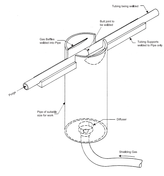
6.4.3 Welding Outside of a Chamber. Conventional GTA welding of tantalum is possible; however, only attempt the most simple operations; for example tacking. Observe the most stringent precautions. A gas shield and jig for small tubing is shown in Figure 7.
6.4.3.1 Tantalum will readily react with contaminants when exposed to them at temperatures as low as 316 C (600 F). Contamination is a time-temperature relationship. Thus, it is possible to tack weld the flanges of a flange joint without incurring damage. When attempting this type operation, break the arc by a remote control foot switch and maintain a post-flow gas shield through the torch until the tack has cooled sufficiently. By limiting tack welds to 0.8-1.6 mm (1/32 -1/16 in) diameter maximum, the area heated by conduction to 316 C (600 F) can be protected by the inert shield of the torch.
6.5 Shielding Gas Monitoring Procedure. There are two general methods that can be used to determine if the purity of the shielding or purge gas in a chamber is satisfactory for welding to commence. A welding atmosphere of 10 ppm maximum contamination is adequate. A purge of 20 volumes produced with a gas flow of 740 L/min (30 cfm) is usually sufficient.
6.5.1 Continuous monitoring of the oxygen content (contamination index) in the shielding gas can be made by means of commercial instrumentation. This equipment obtains a sample, analyzes it, immediately reports the results in ppm, and can send out an alarm. This eliminates the uncertainties and delays discussed in 6.5.2 below.
6.5.2 A backup method involves laying a weld bead on a piece of scrap titanium. If the resultant weld does not show any shade of blue (by observed blue discoloration in any degree) or hardness increase shown by a scratch test, welding may begin. There are several disadvantages to this practice. Changes in the purity of the inert atmosphere while welding will not be detected in time to avoid weld contamination. Pockets of air in a chamber may also go undetected. In addition, it is not possible to observe the effect of purging procedural changes in order to select the procedure which will result in the shortest purge time. Use a follow-up check weld on a piece of titanium scrap to verify that the titanium welding atmosphere was adequate.
6.6 Joint Preparation for Welding. The basic requirement in welding thin sections is to make sure, by whatever means possible, that both joint edges are in continuous contact and that both edges melt simultaneously to form a single weld pool. Separation between the joint edges before or during welding will cause the edges to melt back and remain separate.
6.6.1 Obtain increased latitude in butt joint fixturing tolerances by flanging the edges as shown on Figures 4 and 5 to the tolerances defined in Tables I and II. The turned-up edges act as preplaced filler metal to fill the gap and assure fusion across the joint. They also stiffen the joint edges to minimize warpage from heat buildup during welding.
6.6.1.1 Figure 3 shows the fit-up tolerances for edge joints. The permissible tolerances are much greater than those for butt joints. Because of this wide tolerance, an edge joint is the easiest and most reliable joint for welding foil thicknesses. Successful welding of foil thickness assemblies is greatly assured by using edge or flange joints wherever possible.
6.6.1.2 In metal thickness of 0.051-1.524 mm (0.002-0.060 in), edge flange welds can be made by the melt-in technique. Typical flange heights are shown in Table II and on Figure 2.
6.6.1.3 Table I and Figure 1 show the tolerances for butt joint gap mismatch, and fixture dimensions for heat sink clamps. The tolerances are listed in relation to the metal thickness. Thus, for a square-groove weld in a butt joint, a maximum joint gap of 0.2t is permitted. This is a very small gap. Tool the fixturing for such weldments with precision. Hence, the advantage of a flanged type joint becomes apparent.
6.7 Technique for Flanged Butt Welds (Edge Welds). The flanged surfaces are clamped and approximately four or five small tack welds made around the flange. The flange surface is successively fused and reduced in diameter by a series of passes around the pipe. When complete, the flange has melted down to form a weld deposit that is the same as the tube OD. See Figures 4 and 5.
7. Inspection and Testing
7.1 The quality of a tantalum weld is almost wholly a function of the adequacy of the preweld cleaning operation and the purity of the inert gas shielding.
7.2 About 99 percent of the defects found in tantalum welds are cracks caused by contamination. The most meaningful test is a visual inspection of production joints, coupled with bend tests performed periodically; see 7.6 and Figure 6.
7.3 A characteristic of tantalum welds is pronounced grain boundaries that look very much like cracks or fissures; a dye check will often give a very faint intermittent indication. Ignore this type of indication. Cracking, if present, will be easily discerned by visual inspection alone. Use a hand magnifier as an aid.
7.4 A contaminant-free weld will have a very bright, shiny, silver appearance, similar to highly polished hard chrome plate. As contamination levels increase, the appearance progresses to a dull, then cloudy, finish and cracking may be found prior to the onset of the final frosty surface appearance.
7.5 Precede any contemplated welding work by an extensive program of welding training and testing. Until the welder can produce a surface finish defined in 7.4, there is no need of making bend tests.
7.6 A very simple but effective bend test can be performed by hammering a weld sample to an angle of 180 degrees around a rod. The width of the sample shall be 10 to 20 times the thickness of the sample with a length five times the width. The rod shall be about six times the thickness of the sample. A 12.7 mm (1/2 in) diameter rod is satisfactory for thickness up to 2.4 mm (3/32 in). See Figure 6.
7.7 Tantalum becomes hard and brittle when infused with a contaminant. A crude scratch test can provide a first indication of contamination. This hardness can be tested more accurately by using a proper tester which operates on an electro-mechanical principle. This instrument, which employs a diamond-tipped rod vibrating at ultrasonic frequencies, contacts the surface and the influence of the surface hardness changes the frequency of the rod vibration which is converted electronically for a read-out on a meter. The instrument can be calibrated for tantalum in the hardness range specified (50 Rockwell C) using specimens prepared to indicate a fairly wide range of contamination, thus allowing a ‘go/no-go’ inspection. If the hardness is above the specified limit, occasionally the hardened area can be removed by sanding (water cooled) 0.051 or 0.076 mm (0.002 or 0.003 inch). If the hardness is not removed, remove and replace the welded area completely.
7.8 The amount and type of inspection required depends upon the service conditions and hazards to personnel and property. It is the responsibility of the originator to define the inspection requirements. Inspection shall be in accordance with applicable code(s).
8. Repair and Field Welding
8.1 Repair work requires the same degree of cleanliness and gas coverage purity described previously.
8.2 For welds which shall be repaired due to cracking, completely remove the crack and any adjacent base metal whose ductibility has been impaired.
8.3 Both field and repair welding require extensive study and evaluation prior to striking an arc. If contamination, burn-through, or simple lack of fusion is encountered, the resultant repair cost can be disastrous.
9. Qualification Procedure
A sample of qualification procedure is provided in Appendix A. The information contained in this sample may be useful in qualifying your own welding procedure.
TABLE I – Tolerances for Butt Joints in Thin Materials

FIGURE 1 – Permissible Joint Tolerances
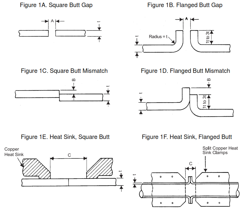
TABLE II – Flange Heights for Edge Flange Welds
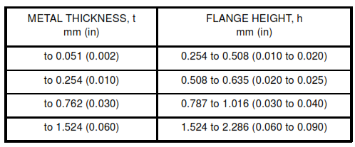
FIGURE 2 – Flange Heights for Edge Flange Welds
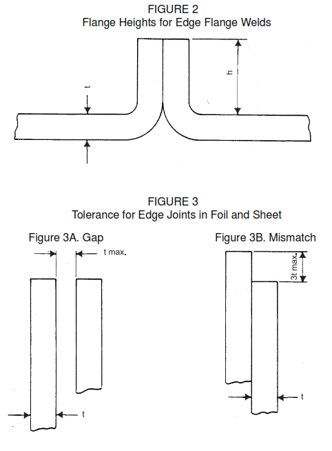
FIGURE 4 – Butt Welding Technique for Tantalum Tubing (For heat sinks see Figure 1F)
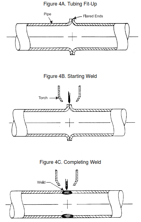
FIGURE 5 – Flange Facing Welding Procedure for Tantalum Lined Pipe
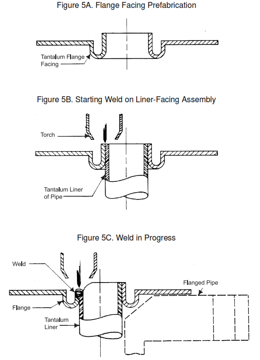
FIGURE 6 – Suggested Bend Test for Tantalum Welder Qualification Testing
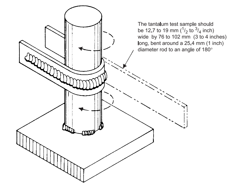
FIGURE 7 – Gas Shield and Jig for Small Tubing
Check all appendices in this document.
Format for Welding Procedure Specification