CORESET (Control Resource Set) is a new concept introduced in 5G NR for downlink control signaling, addressing some limitations present in LTE and enhancing flexibility in control channel design.
CORESET vs. LTE Control Region.
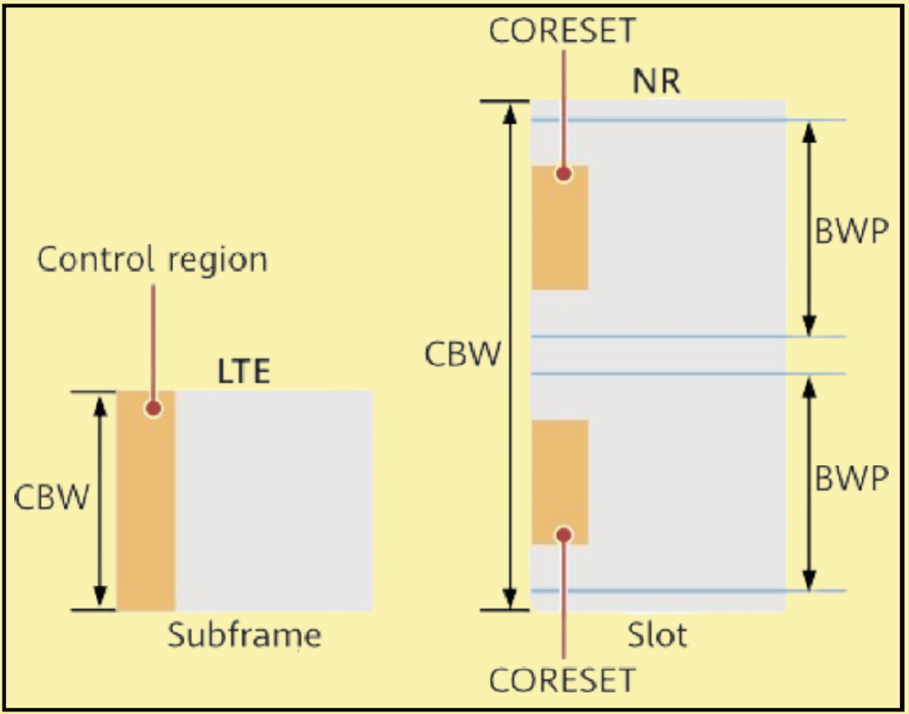
- LTE PDCCH: In LTE, the Physical Downlink Control Channel (PDCCH) occupies the entire carrier bandwidth in the frequency domain and one to three OFDM symbols in the time domain. This area is known as the control region. This design is feasible because LTE UEs support a maximum carrier bandwidth of 20 MHz. However, this broad allocation can lead to interference management challenges between neighboring cells.
- NR CORESET: NR introduces the concept of CORESET to manage control signaling more efficiently:
- Scalable Bandwidth: 5G NR supports system bandwidths up to 400 MHz. Allocating the PDCCH across this entire bandwidth would be inefficient and overly complex, especially for UEs unable to process signals across such a wide range.
- Frequency-Domain Flexibility: CORESET allows the PDCCH to occupy a specific, configurable part of the bandwidth, which helps in managing interference and optimizing resource usage.
- Time-Domain Flexibility: The start position of the PDCCH in the time domain is also configurable, adding another layer of flexibility.
- Encapsulation: Information about the frequency range and the number of OFDM symbols occupied by the PDCCH is encapsulated into CORESET.
CORESET and Search Spaces.
In 5G NR, control signaling uses two main concepts:
- CORESET: Defines the frequency and time resources used by the PDCCH. It specifies the OFDM symbols and the frequency resources that the PDCCH will occupy.
- Search Space: Specifies the monitoring occasions for the PDCCH within a CORESET. It includes information about the starting OFDM symbol and the periodicity of the PDCCH.
Each search space is linked to a CORESET, and the combination of these determines the PDCCH configuration, allowing UEs to decode the PDCCH successfully by knowing both the frequency and time positions.
Figure 1 – Difference in control channel resource allocation between LTE and NR.

CORESET in Time and Frequency Domains.
Time Domain.
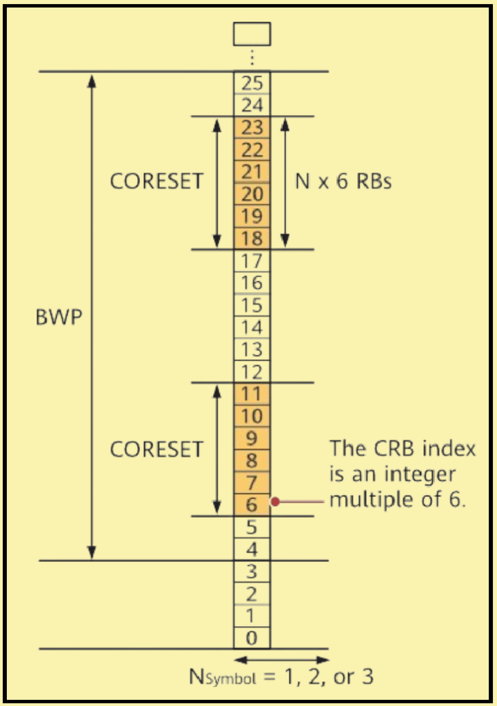
- Symbol Occupation: A CORESET in 5G NR occupies one, two, or three OFDM symbols.
- Start Symbol Flexibility: The starting symbol of a CORESET can be any symbol within a slot, though it is often placed at the start of a slot to facilitate data reception, similar to the control channel in LTE.
- Mid-Slot CORESET Placement: For services requiring extremely low latency, CORESET can be placed in the middle of a slot. This allows data to be sent immediately without waiting for the next slot.
Frequency Domain.
- RB Occupation: A CORESET occupies an integer multiple of 6 resource blocks (RBs).
- BWP Constraints: The CORESET must be within the frequency range of the Bandwidth Part (BWP).
- CRB Positioning: The starting position of a CORESET must align with a common resource block (CRB) index that is an integer multiple of 6. For example, if the BWP starts at CRB index 4, the CORESET must start at a CRB index that is at least 6.
Example Scenario.
- BWP Start Position: Assume the BWP starts at CRB index 4.
- CORESET Start Position: The CORESET must be configured at a CRB index of at least 6, ensuring proper alignment and resource allocation within the BWP.

CORESET Types and Configuration.
Multiple CORESETs for System Flexibility.
- Multiple CORESETs: NR supports multiple CORESETs to enhance system flexibility.
- Maximum in a Single BWP: Up to three CORESETs (including CORESET 0 if configured) and up to 10 search spaces (including search space 0 if configured) can be configured in a single BWP.
- Cell Configuration Limits: With up to four BWPs per cell, a cell can have up to 12 CORESETs (CORESETID 0-11) and up to 40 search spaces (SearchSpaceID 0-39).
CORESET Classification.
CORESETs are classified based on their usage scenarios into CORESET 0 and common CORESETs.
CORESET 0
- Initial Access Role: CORESET 0 is part of the initial BWP configuration and is provided to UEs via the master information block (MIB).
- Function: UEs use CORESET 0 to obtain scheduling information for SIB1 to complete initial access.
Common CORESETs
- Post-RRC Connection: After an RRC connection is established for a UE, one or more common CORESETs are configured for the UE through an RRC configuration message.
- Usage: These common CORESETs are used for various control signaling needs once the UE is connected to the network.
Details on Configuration.
- CORESETID and SearchSpaceID: CORESETs and search spaces are identified by unique IDs within their respective ranges.
- Standards Reference: Detailed configuration information can be found in section 6.3.2 “Radio resource control information elements” in 3GPP TS 38.331 V15.5.1.
Example.
To better understand the distinction and configuration of CORESETs:
- Initial Access: A UE receives the MIB containing CORESET 0 configuration to initiate access.
- Post-Access: Upon establishing an RRC connection, the network configures additional common CORESETs via RRC signaling for ongoing communication needs.