Frequency converters paired with asynchronous motors primarily find application in adjusting and controlling operational speeds. In lower power ranges, typically up to a few kilowatts, they serve as viable alternatives to soft starters for motor startups due to cost-effectiveness and enhanced functionality.
Commonly employed in pump and fan drives, frequency converters optimize acceleration, deceleration, and operational speed control to achieve energy efficiency. They facilitate precise adjustments to the speed characteristic, often using linear ramps, unlike soft starters where speed regulation relies on motor voltage and load characteristics.
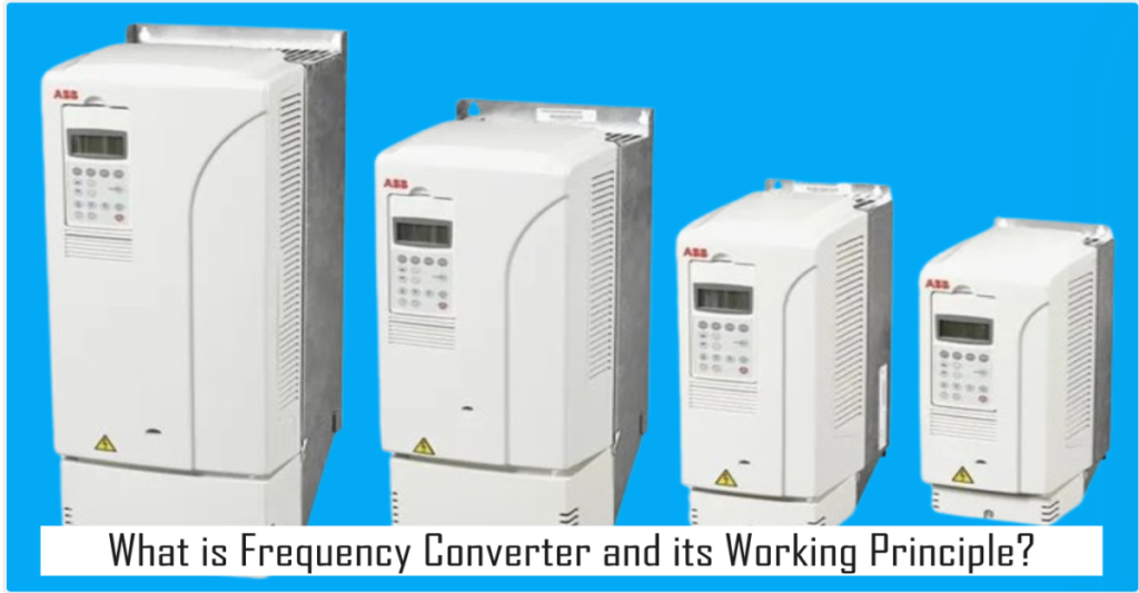
An advantage of frequency converters for motor startups is the availability of full motor torque within the speed range up to synchronous speed. Unlike soft starters, where speed regulation is limited by motor voltage and load characteristics, frequency converters provide flexibility in setting and specifying speed characteristics.
Frequency Converter Working Principle.
The fundamental operation and working principle of frequency converters involves several key steps. Initially, the converter transforms the incoming constant voltage and frequency from the power supply into a direct voltage. Using this direct voltage, the converter then produces a new three-phase power supply for the connected three-phase motor, with both variable voltage and frequency.
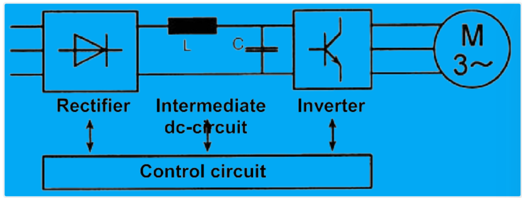
When equipped with an uncontrolled rectifier, the frequency converter draws largely active power (with a power factor close to 1) from the power supply. Meanwhile, the reactive power needed for motor operation is provided by the direct voltage intermediate circuit. As a result, in most scenarios, there is no necessity for a power factor compensation device on the supply side.
Particularly regarding advanced features such as frequency converters with vector control and slip compensation, or inverters with magnetic flux control can also be considered.
1. Rectifier.
The rectifier serves as the link between the external power supply and the system, converting alternating current (AC) into direct current (DC). With an uncontrolled rectifier, the output voltage is characterized by ripple, and its amplitude typically equals the peak value of the connected supply voltage (Ue · √2).
In applications with low power ratings, typically up to around 2.2 kW, single-phase bridge rectifiers are commonly used due to cost considerations. For higher power ratings, three-phase rectifiers are preferred to ensure efficient and reliable operation. These rectifiers play a crucial role in providing a stable DC voltage supply, essential for powering various components within the system.
2. Intermediate circuit.
The intermediate circuit of a frequency converter plays a important role in maintaining a stable supply of direct voltage. It serves as a storage reservoir for energy and works to smooth out fluctuations in the voltage output. When the motor connected to the frequency converter draws energy from the intermediate circuit, it causes a partial discharge of the capacitor within the circuit. This discharge is replenished when the supply voltage exceeds the voltage level of the intermediate circuit.
During periods when the supply voltage approaches its maximum level, the energy for recharging the intermediate circuit is derived from the power supply. This can lead to current peaks, which need to be considered when selecting upstream switchgear such as contactors or circuit breakers. It’s important to note that the ratings of these devices are typically based on sinusoidal currents.
For larger power ratings, typically above approximately 5.5 kW, intermediate circuit chokes (denoted as L) are incorporated. These chokes extend the duration of current flow on the supply side, effectively reducing current peaks. By mitigating these peaks, intermediate circuit chokes contribute to smoother operation and help ensure the reliability of the connected electrical system.
3. Inverter.
The inverter is responsible for generating a three-phase power supply with the desired frequency and voltage to drive the connected motor. To achieve this, the components of the inverter, under the control of the system’s logic, alternate between connecting positive and negative voltage pulses to the motor coil.
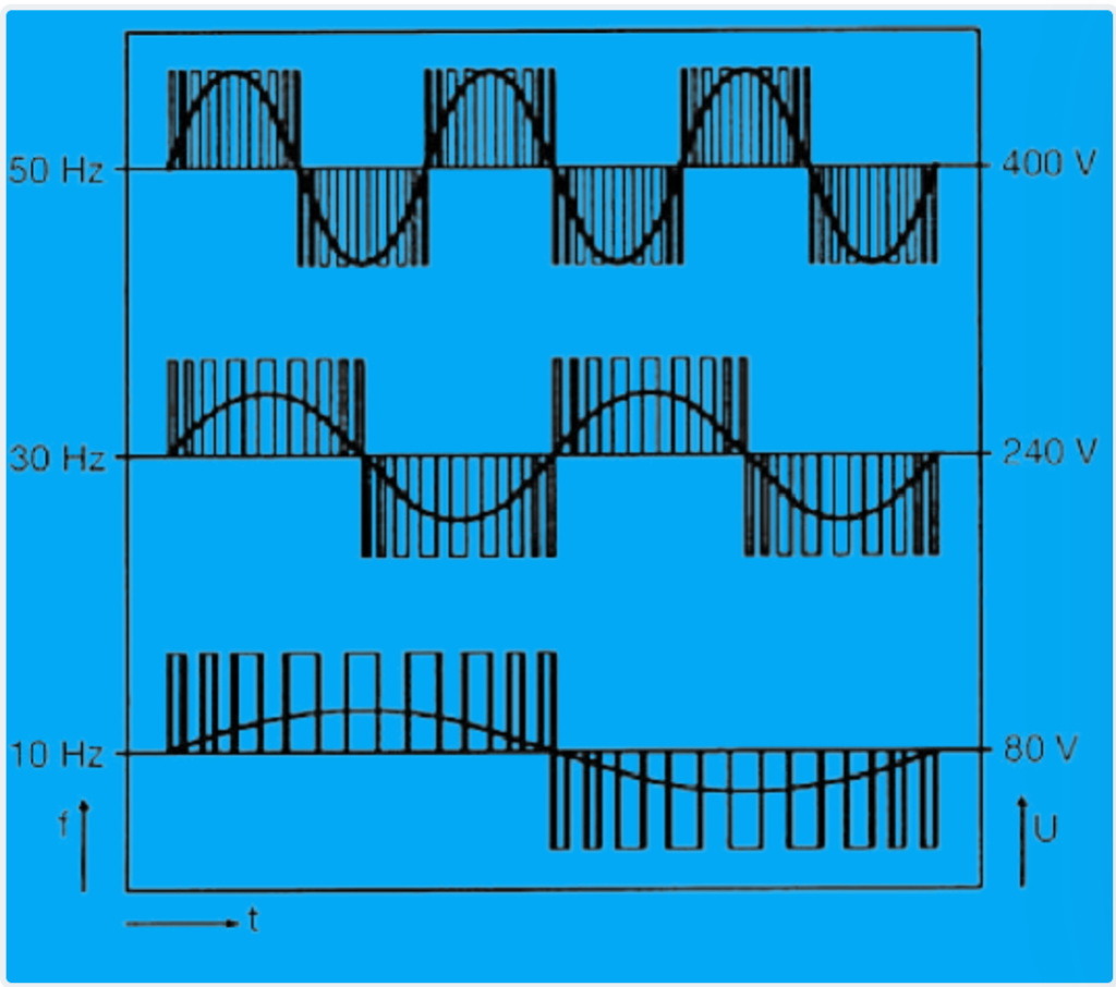
The high switching frequency used by the inverter, often exceeding the audible range, results in the creation of a largely sinusoidal motor current. This occurs through interaction with the inductances of the motor, which help smooth out the output waveform.
In most frequency converters, the control of frequency and voltage is achieved using a technique known as pulse width modulation (PWM). This method involves varying the width of the voltage pulses supplied to the motor coil while maintaining a constant amplitude. By adjusting the pulse width in proportion to the desired output frequency, the inverter can effectively regulate both the speed and voltage of the motor, ensuring precise control over its operation.
Operational performance.
The operational performance of squirrel-cage induction motors is governed by a fundamental characteristic known as the U/f characteristic curve. This curve dictates that the motor voltage should decrease proportionally to the frequency of operation. This relationship is crucial because the magnetic field within the motor is essential for generating torque, and preventing saturation of the iron core is paramount.
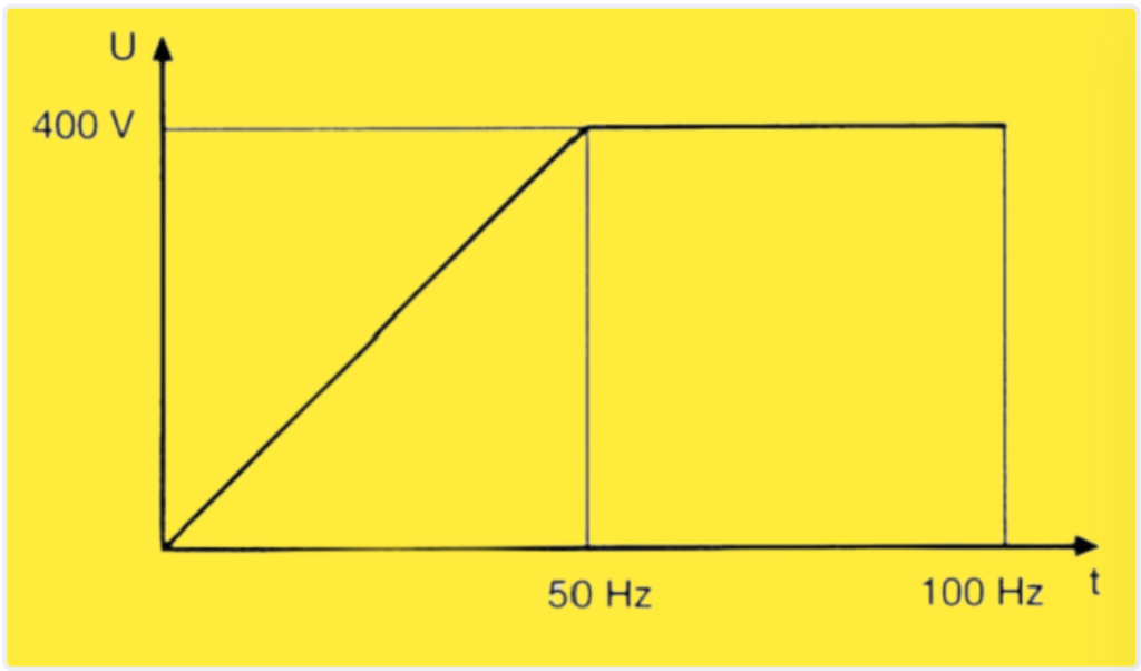
Frequency converters are typically designed to ensure that the motor voltage reaches its maximum value at synchronous speed and remains constant at higher frequencies. Beyond synchronous speed, however, the available torque decreases, allowing the drive to operate at constant power.
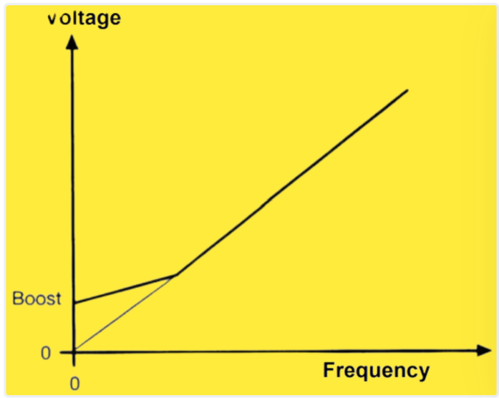
At low frequencies, typically below approximately 5 Hz, the voltage drop across the motor’s internal ohmic resistances becomes more significant relative to the voltage across the motor inductances, which are proportional to the frequency. This imbalance can lead to inadequate magnetization and a subsequent reduction in torque. To address this issue, voltage boost is applied at low speeds to compensate for the diminishing magnetization and maintain torque output.
Change of sense of rotation and braking.
Changing the direction of rotation in a frequency converter-driven motor is a straightforward process accomplished through a control command, as the rotating field is electronically generated.
When the frequency is decreased while the motor is running, the rotor tends to rotate faster than the rotating field, leading to what’s known as the over-synchronous mode. In this mode, the motor effectively acts as a generator, producing energy that is fed back to the frequency converter. This energy is then stored in the intermediate circuit of the converter. However, if this energy is not properly managed, it can result in a voltage rise, potentially leading to a protective shutdown.
To mitigate the risk of voltage rise and ensure proper handling of the generated energy, several methods can be employed:
- Electronically controlled dissipation of the energy using a resistance, effectively converting the excess energy into heat.
- Feedback of the energy into the power supply through an inverter, allowing it to be redistributed or utilized elsewhere in the system.
- Connecting the intermediate circuits of multiple frequency converters and utilizing the braking energy to power other connected motors, effectively recycling the energy within the system.
By implementing these methods, the frequency converter system can efficiently manage the energy generated during braking and ensure smooth operation without risk of voltage rise or system shutdown.
Motor protection.
Frequency converters typically come equipped with integrated electronic motor protection systems, rendering additional protection unnecessary under normal circumstances. However, for specialized applications, such as supplying multiple motors via a single inverter, additional motor protection for each motor may be required.
When employing overload protective devices with bimetal tripping mechanisms to safeguard individual motors, it’s essential to consider that the harmonic content of the output current from frequency converters may alter the characteristics of these protective devices. Additionally, these devices may experience additional thermal loading due to the presence of harmonics.
It’s important to note that self-ventilating motors are not suitable for continuous operation at low speeds. In such scenarios, external ventilation should be provided to prevent overheating. To ensure motor protection even at low speeds, temperature sensors such as thermistors (PTC) should be installed in the motor windings. These sensors can detect excessive temperatures and trigger protective measures to prevent damage to the motor.