An impulse turbine is a type of steam or hydraulic turbine where the energy transfer from the fluid to the rotor wheel occurs primarily due to the change in velocity of the fluid. In an impulse turbine, the fluid (such as steam or water) enters the turbine with high pressure and passes through a series of fixed nozzles or guide vanes. As the fluid passes through these nozzles or guide vanes, its velocity is significantly increased, while its pressure remains relatively constant.
Impulse Turbine Working Principle
The single-stage impulse turbine, also known as the de Laval turbine, is named after its inventor, Gustaf de Laval. This type of turbine consists of a single rotor to which impulse blades are attached. In the single-stage impulse turbine, steam is fed through one or several convergent-divergent nozzles. These nozzles are designed in such a way that they do not extend completely around the circumference of the rotor. As a result, only part of the turbine blades is impinged upon by the steam at any given time.
The design of the nozzles also allows for the governing of the turbine’s speed and output. By shutting off one or more of the nozzles, the flow of steam to the turbine can be controlled, thereby regulating the turbine’s operation.
A schematic representation of the single-stage impulse turbine is shown in Figure 4.4. This type of turbine is commonly used in various applications where a single stage of expansion is sufficient to achieve the desired output.

A velocity diagram for a single-stage impulse turbine is depicted in Figure 4.5. This diagram illustrates the flow of steam through the turbine blades and helps in understanding the relationship between different velocities involved in the turbine operation.
In the velocity diagram, a velocity triangle is often used to visually represent the velocities. The adjacent figure provides a breakdown of the velocity triangle, which typically includes:

Tangential force on a blade:
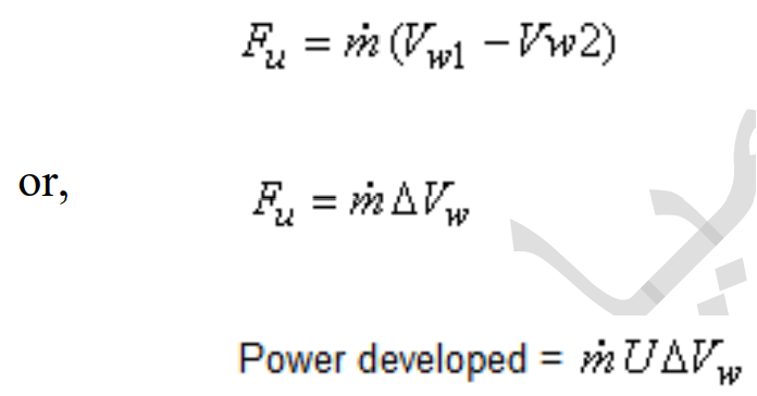
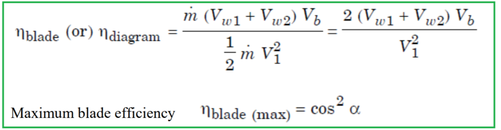
Blade efficiency
Blade efficiency is a measure of how effectively a turbine blade converts the energy of the fluid (such as steam or water) into mechanical work. It is defined as the ratio of the power developed by the turbine to the energy entering the blade per second.
Mathematically, blade efficiency can be expressed as:
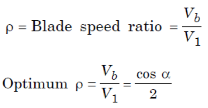
Blade speed ratio
Blade speed ratio, also known as velocity ratio or specific speed, is a dimensionless parameter used in the design and analysis of turbomachinery, including turbines and pumps.
Mathematically, blade speed ratio is expressed as:
Stage Efficiency
Stage efficiency is a measure of how effectively a stage in a turbine or compressor converts the energy of the fluid into useful work. It is defined as the ratio of the actual work done per unit time (or power) in one stage to the theoretical work that would be done if the process were isentropic (i.e., reversible adiabatic) with the same enthalpy drop.
Mathematically, stage efficiency (ηs) can be expressed as:
Mathematically, stage efficiency (ηs) can be expressed as:
ηs=Actual Work Done per Second in One Stage / Isentropic Enthalpy Drop in One Stage


If blade friction coefficient (K) is given then Vr2=KVr1
Unless otherwise stated, we can take V2=Vr1
Compounding in Impulse Turbine
Compounding in an impulse turbine is essential because allowing high-velocity steam to flow through just one row of moving blades would result in a rotor speed that’s too high for practical use, around 30,000 revolutions per minute (rpm). To make the turbine more practical and efficient, compounding techniques are employed. Compounding involves incorporating multiple sets of nozzles and rotors in a series, all connected to the same shaft. This allows the turbine to absorb the energy of the steam in stages, either by reducing the steam pressure or by controlling the velocity of the steam jet.
There are three main methods of compounding in an impulse steam turbine:
1. Velocity compounding
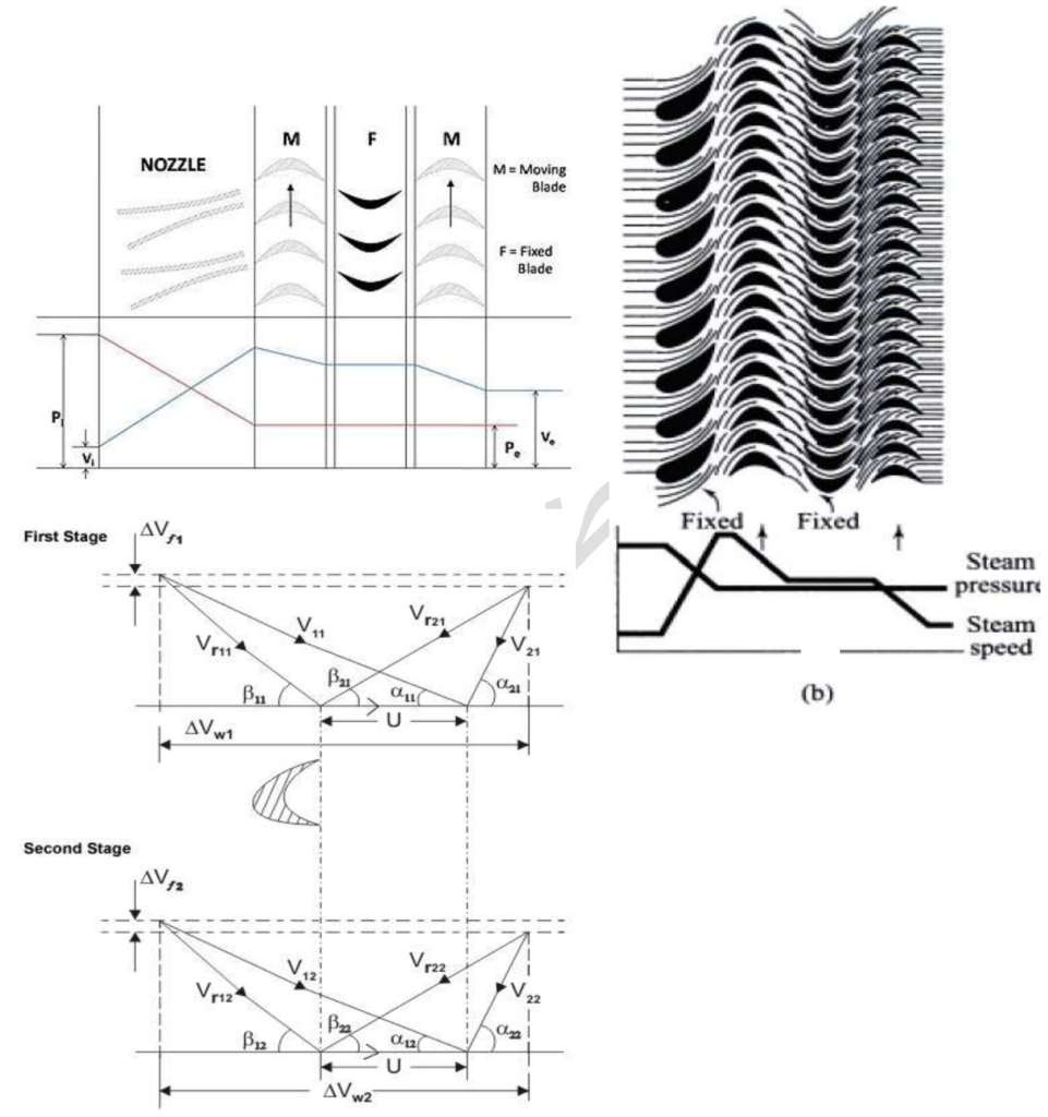
Velocity compounding in turbines involves using multiple rows of moving blades, separated by rows of fixed blades, to gradually reduce the velocity of the steam as it passes through the turbine stages. In the Curtis stage turbine, for example, there is one stage of nozzles followed by two rows of moving blades, with a row of fixed blades in between. These fixed blades redirect the steam from the first row of moving blades to the second row.
In a Curtis stage turbine, the total pressure drop occurs in the nozzles, ensuring that the pressure remains constant in all rows of blades. However, the velocity of the steam decreases as it passes through the moving blades, leading to a reduction in kinetic energy.
where,
Pi = pressure of steam at inlet
Vi = velocity of steam at inlet
Po = pressure of steam at outlet
Vo = velocity of steam at outlet
In the above turbine picture, there are two sets of moving blades arranged in rings, with a single ring of fixed blades positioned between them. As mentioned earlier, the pressure drop in the turbine stage primarily occurs within the nozzles, and there are no additional pressure losses in the subsequent stages. However, the velocity of the steam decreases as it passes through the moving blades, contributing to a drop in kinetic energy. It’s important to note that this velocity reduction occurs specifically within the moving blades, while the fixed blades serve to guide and redirect the steam flow without directly affecting its velocity.
Disadvantages of velocity compounding include:
- High friction losses due to the high steam velocity.
- Lower work produced in the low-pressure stages compared to other compounding methods.
- Difficulty in designing and fabricating components capable of withstanding such high velocities, leading to challenges in manufacturing.
Despite these drawbacks, velocity compounding can still be an effective method for increasing the efficiency and performance of impulse turbines, especially when combined with other compounding techniques.
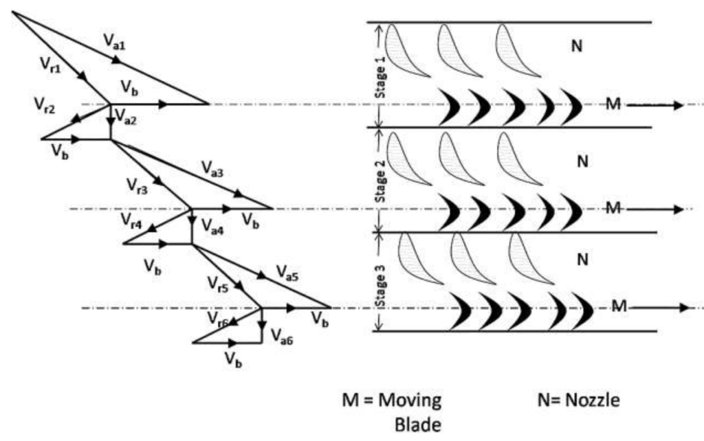
2. Pressure Compounding of Impulse Turbine
Pressure compounding in impulse turbines, also known as Rateau turbines, addresses the challenge of high blade velocity encountered in single-stage impulse turbines. In this design, alternate rings of nozzles and turbine blades are utilized, with the nozzles attached to the casing and the blades connected to the turbine shaft.
Unlike velocity compounding where the steam is expanded in a single stage (nozzle), pressure compounding involves expanding the steam across multiple stages. This expansion is achieved through the use of fixed blades acting as nozzles. Each row of fixed blades facilitates the expansion of steam, resulting in a gradual decrease in pressure and an increase in velocity.
Here’s how pressure compounding works:
- The steam from the boiler enters the first set of fixed blades, known as the nozzle ring.
- As the steam passes through the nozzle ring, it undergoes partial expansion, leading to a partial decrease in pressure.
- This decrease in pressure causes an increase in the velocity of the steam within the nozzle.
- Therefore, by the time the steam exits the nozzle, its pressure has decreased partially, while its velocity has increased.
By expanding the steam across multiple stages using fixed blades, pressure compounding allows for a more gradual reduction in pressure and a controlled increase in velocity. This approach helps to mitigate the challenges associated with high blade velocity and improves the overall efficiency and performance of the impulse turbine.

3. Pressure-Velocity compounded Impulse Turbine
The pressure-velocity compounded impulse turbine is a hybrid design that combines elements of both velocity and pressure compounding techniques. In this configuration, the total pressure drop of the steam is divided into multiple stages, each comprising rings of fixed and moving blades.
Here’s how the pressure-velocity compounded impulse turbine works:
- Each stage of the turbine consists of one ring of fixed blades and 3-4 rings of moving blades.
- The fixed blades in each stage facilitate the expansion of steam, acting as nozzles to control the pressure drop.
- As the steam passes through the fixed blades, it undergoes partial expansion, resulting in a decrease in pressure and an increase in velocity.
- The partially expanded steam then enters the rings of moving blades, where additional energy is extracted as the steam imparts rotational motion to the turbine shaft.
- The moving blades redirect the flow of steam and further increase its velocity, contributing to the overall energy conversion process.
- Each stage of the turbine operates as a velocity-compounded impulse turbine, with the moving blades effectively converting the kinetic energy of the high-velocity steam into mechanical work.
By dividing the pressure drop into multiple stages and incorporating both fixed and moving blades in each stage, the pressure-velocity compounded impulse turbine achieves a more efficient and controlled extraction of energy from the steam. This hybrid design optimizes the performance of the turbine and allows for a wider range of operating conditions and applications.
