An inverter is an electrical device or circuit that converts direct current (DC) into alternating current (AC). Inverters are essential in various applications, enabling the use of DC power sources, such as batteries or solar panels, to operate AC-powered devices and systems.
Following is the basic configuration of inverter.
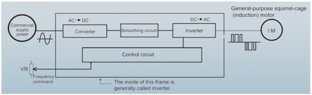
An inverter typically consists of several key components, each serving a specific function in the process of converting direct current (DC) into alternating current (AC) with variable frequency.
What is Inverter?
Inverter Components:
Here’s an overview of these components and their functions:
- Converter Circuit:
- Function: The converter circuit is responsible for transforming the incoming commercial AC power supply into DC power. This is typically achieved using diodes or transistors arranged in a rectifier circuit. The goal is to provide a stable source of DC voltage for the inverter.
- Smoothing Circuit:
- Function: DC power generated by the converter circuit often contains pulsations or ripples. The smoothing circuit’s function is to reduce these pulsations and provide a relatively stable and smooth DC voltage. This is typically achieved using capacitors that store energy and release it to maintain a more constant voltage.
- Inverter Circuit:
- Function: The inverter circuit is the heart of the inverter. It takes the smoothed DC voltage from the smoothing circuit and converts it back into AC voltage. Importantly, the inverter allows for control of the frequency and voltage of the output AC power. This is crucial because different applications require AC power with varying frequency and voltage levels.
- Control Circuit:
- Function: The control circuit is responsible for managing and regulating the entire inverter system. It monitors the output voltage and frequency, adjusts them as needed, and ensures the inverter operates efficiently and safely. It also provides protection features to prevent overloading, overheating, and other potential issues. The control circuit may use microcontrollers or specialized control chips to perform these functions.
Principle of Converter:
The operation of a converter in creating direct current (DC) from an alternating current (AC) power supply is based on rectification principles. Here’s an explanation of the key components and the method used for this conversion:
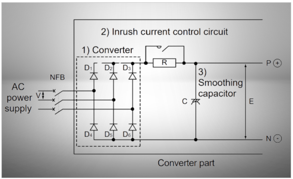
Components of the Converter Part:
- Converter: This is the primary component responsible for rectifying AC power into DC. It typically contains diodes or other semiconductor devices.
- Inrush Current Control Circuit: This circuit is designed to control the inrush current that can occur when the AC power is initially connected to the converter. It helps prevent damage to components and circuits due to excessive current flow.
- Smoothing Circuit: The smoothing circuit, often consisting of capacitors, is used to reduce voltage pulsations or ripples in the rectified DC output, providing a more stable DC voltage.
1. Method to Create DC from AC:
Let’s consider a simplified example using single-phase AC as the power source:
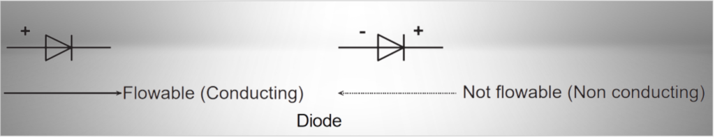
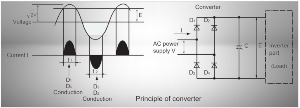
- Basic Principle of Diode Operation: Diodes are semiconductor devices that allow current to flow in one direction while blocking it in the opposite direction. In other words, diodes conduct when a positive voltage is applied to their anode (A) relative to their cathode (B), and they block current flow when the voltage polarity is reversed.
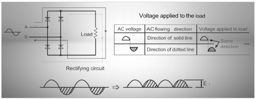
- Rectification Process: When AC voltage is applied between points A and B in the circuit, the voltage alternates in polarity as the AC waveform cycles. However, due to the nature of diodes, they only allow current to flow during the part of the AC cycle when the anode (A) is at a higher voltage than the cathode (B).
- Conversion of AC to DC: As a result, when AC voltage is applied to the circuit, the diodes only permit current flow in one direction (either the positive half-cycle or the negative half-cycle, depending on diode orientation). This effectively “rectifies” the AC voltage, turning it into DC voltage. This process is known as rectification.
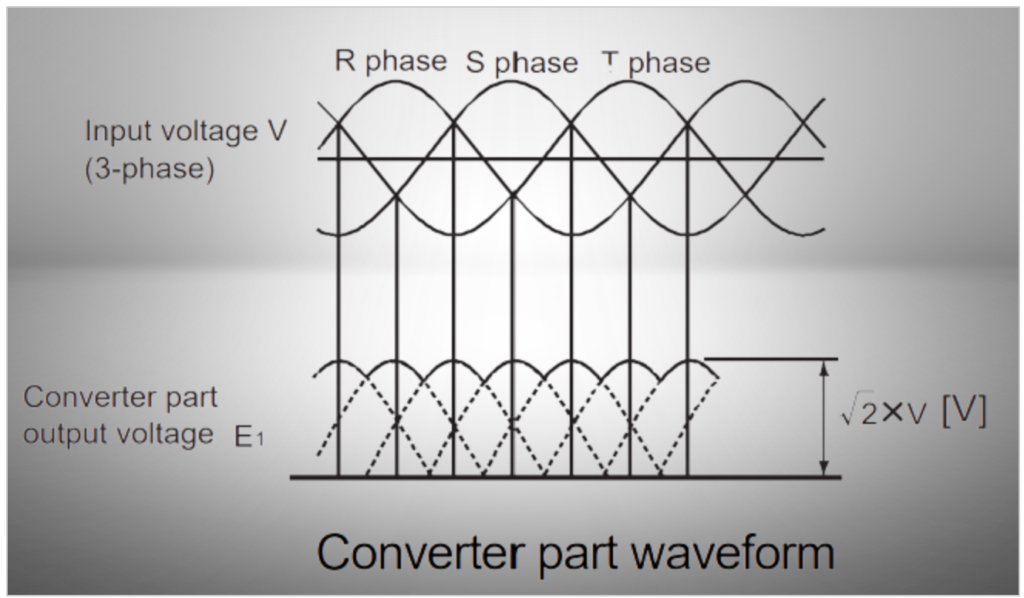
When dealing with three-phase AC input, we use a set of six diodes to rectify the alternating current into a more stable direct current. This rectification process involves converting the fluctuating AC voltage into a smoother DC voltage.
When a smoothing capacitor is used as the load in a rectifier circuit, it affects the input current waveform. While the principle of rectification is often explained using a resistor, the reality is that capacitors are frequently used to smooth out the DC voltage.
2. Inrush current control circuit
An inrush current control circuit is a crucial component in power supply systems, especially when capacitors are used as part of the load. Here’s a simple description of its purpose and operation:
Purpose: In power supply circuits, capacitors are often used to smooth out the DC voltage. When power is initially applied, capacitors have the natural tendency to draw a large surge of current to charge up quickly. This initial surge of current, known as inrush current, can be significantly higher than the steady-state current required to maintain the capacitor’s charge.
Operation: To protect rectifying diodes and other components from potential damage caused by this high inrush current, an inrush current control circuit is employed.
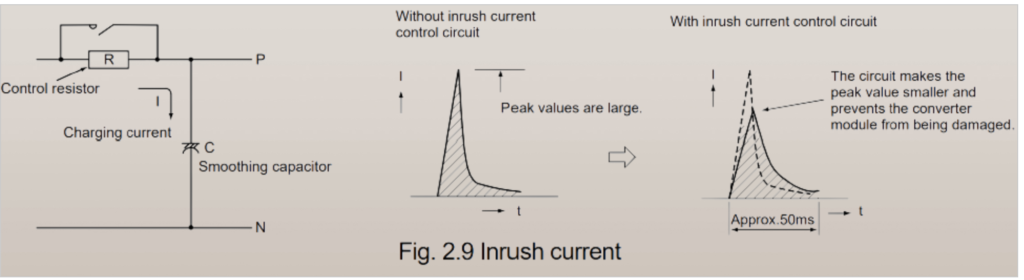
- Initial Inrush Current Limiting: When the power supply is turned on, the inrush current control circuit temporarily connects a series of resistors in line with the capacitors for approximately 0.05 seconds. This series resistance limits the amount of current that can flow into the capacitors during this critical startup period. As a result, the inrush current is controlled and kept within safe limits.
- Resistor Bypass: After the initial startup period (0.05 seconds in this example), a magnetic switch or similar mechanism is used to short-circuit or bypass the series resistors. This effectively removes the additional resistance from the circuit, allowing the capacitors to charge up more rapidly and operate at their intended performance levels.
- Protection: The inrush current control circuit acts as a protective mechanism, ensuring that the initial surge of current does not overwhelm the components, especially the rectifying diodes, which can be sensitive to high current levels. By limiting the inrush current, it prevents potential damage and extends the lifespan of the circuit.
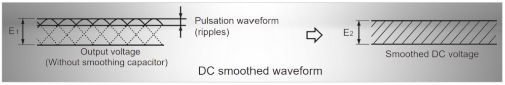
3. Smoothing circuit operation Principle
The principle of smoothing circuit operation is essential for converting a rectified DC voltage with pulsations (E1) into a more stable and continuous DC voltage (E2) using a smoothing capacitor.
Inverter Operation Principle
1. Method to create AC from DC
Creating alternating current (AC) from direct current (DC) is a fundamental process that’s widely used in various applications. This transformation is made possible by a device called an inverter, and the basic principle behind it can be explained using a simple single-phase DC source.
Imagine starting with a single-phase DC power supply, which typically provides a constant voltage in one direction. To illustrate this process, let’s consider a common household item: a lamp. The goal is to create an AC voltage that can power the lamp.
Now, we introduce four switches, labeled S1 to S4. These switches are like electronic gates that can be opened (turned on) or closed (turned off) to control the flow of current from the DC power supply to the lamp. They play a crucial role in the inverter’s operation.
To get started, we pair the switches as follows: S1 is paired with S4, and S2 is paired with S3. These pairs of switches will alternate between being turned on and off.
Here’s how it works: When we turn on switches S1 and S4, the current flows from the DC power supply through the lamp in one direction, which we’ll call direction A. This causes the lamp to illuminate, creating light. However, this is just the beginning.
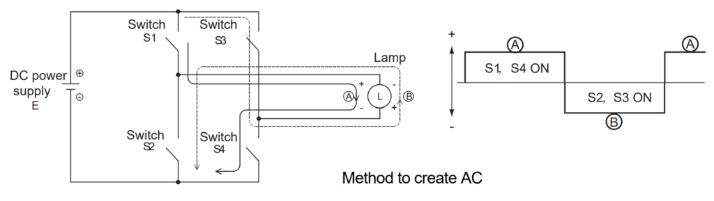
After a certain period of time, we don’t just leave switches S1 and S4 on. Instead, we simultaneously turn them off and, at the same time, turn on switches S2 and S3. This action effectively reverses the current flow through the lamp, now in the opposite direction, which we’ll call direction B. The lamp’s current direction alternates.
This alternating action is repeated continuously, with switches S1/S4 and S2/S3 taking turns being on and off. As a result, the current flowing through the lamp constantly changes direction, creating a pattern that resembles the behavior of standard AC power sources.
In practice, real inverters use electronic components such as transistors or integrated circuits to switch the DC current flow back and forth rapidly. This produces a continuous AC waveform with the desired frequency and voltage level. This AC output can then be used to power various electrical devices and systems that rely on AC power.
2. Method to change frequency
The frequency of the alternating current (AC) generated by the inverter can be adjusted by changing the period during which the switches S1 to S4 are turned on and off. In this simple example, let’s say we turn on switches S1 and S4 for 0.5 seconds and switches S2 and S3 for 0.5 seconds, and then repeat this operation.
When we use this 0.5-second ON and 0.5-second OFF cycle, the AC waveform produced has one complete alternation per second, which means it has a frequency of 1 Hertz (Hz). In electrical terms, Hertz is the unit of frequency, and it represents the number of complete cycles or alternations that occur in one second.
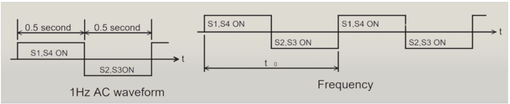
The general formula to calculate the frequency (f) of the AC waveform based on the time period (t0) for one cycle is:
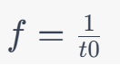
So, if switches S1/S4 and S2/S3 are turned on and off for the same period, and the total time for one complete cycle is t0 seconds, then the frequency (f) of the AC waveform is equal to f=1/t0 Hertz.
By adjusting the ON and OFF periods of the switches in the inverter circuit, we can precisely control the frequency of the generated AC power. This ability to vary the frequency is crucial in many applications, as different devices and systems may require AC power with specific frequencies to operate optimally.
3. Method to change voltage
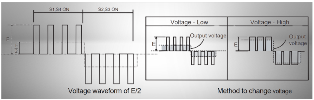
Controlling the output voltage of the inverter can be achieved by adjusting the duration for which the switches are turned on and off. In this scenario, shorter periods of switch activation result in changes in voltage. Let’s break down how this works:
- Voltage Control: To control the output voltage, consider a situation where switches S1 and S4 are turned on for only half of the total period. When this happens, the output voltage becomes E/2, which is half of the DC voltage E. Essentially, by reducing the time during which the switches are on, we obtain a lower output voltage.
- Higher Voltage: Conversely, if you want a higher output voltage, you would extend the duration for which the switches are turned on. By keeping them on for a longer period within the cycle, you can achieve an output voltage that’s closer to the full DC voltage E.
- PWM Control: This control method is commonly referred to as Pulse Width Modulation (PWM). PWM precisely controls the width (duration) of pulses of voltage in the output waveform. By adjusting the pulse width, you can effectively control the average voltage level delivered to the load.
- Carrier Frequency: In PWM control, the frequency at which the switches are turned on and off is crucial. This reference frequency is called the “carrier frequency.” The carrier frequency determines the time intervals during which the switches are active (on) or inactive (off). By varying the duty cycle, which is the ratio of the ON time to the total cycle time, you can regulate the average voltage delivered to the load.
4. Three-phase AC
Creating three-phase alternating current (AC) involves a more complex circuit compared to the single-phase example. Let’s understand the basic circuit and the method used to generate three-phase AC:
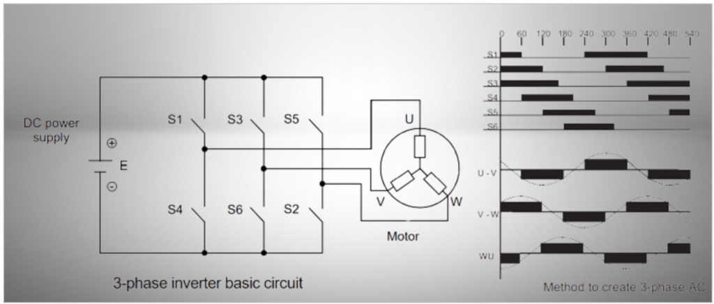
Basic Three-Phase Inverter Circuit: Fig. 2.17 illustrates the basic circuit of a three-phase inverter. It involves six switches, labeled S1 to S6. These switches control the flow of current in the circuit and are essential for creating three-phase AC.
Method for Generating Three-Phase AC: To obtain three-phase AC, you connect all six switches (S1 to S6) to the circuit simultaneously. The key to generating three-phase AC lies in the precise timing of turning these switches on and off, as shown in Fig. 2.18.
The timing and sequence of turning the switches on and off are critical. By following the correct sequence, you can ensure that the three phases of AC voltage have a specific relationship in terms of phase angle and amplitude.
Changing Phase Order and Rotation Direction: One of the advantages of this three-phase inverter circuit is its versatility. By changing the order in which you turn on and off the six switches, you can alter the phase order between the three phases, labeled U, V, and W. Additionally, changing the phase order affects the rotation direction of the generated three-phase AC.
For example, by modifying the switching sequence, you can change the phase order from U-V-W to V-W-U or any other combination. This flexibility is valuable in various applications where different phase sequences and rotation directions are needed.
5. Switch element
The switches (S1 to S6) used in the three-phase inverter circuit are typically semiconductor devices known as IGBTs (Insulated Gate Bipolar Transistors).
6. V/F pattern
The relationship between the frequency (F) and voltage (V) in an inverter, often referred to as the V/F pattern, plays a crucial role in controlling the speed and torque of electric motors. Let’s break down how this pattern works:
1. Motor Speed Control: In many applications, changing the speed of an electric motor is essential. This speed control is achieved by altering the frequency of the power supplied to the motor. When the frequency of the electrical power changes, the motor’s rotational speed changes accordingly. This principle is represented by Formula 1.2.
2. Magnetic Flux and Motor Torque: The torque produced by an electric motor is determined by two primary factors: the magnetic flux (Φ) inside the motor and the current (I) flowing through its coils. This relationship is based on the principles of electromagnetic induction and can be visualized using Fleming’s left-hand rule.

3. Voltage, Frequency, and Magnetic Flux: There is a direct relationship between the magnetic flux (Φ), the voltage (V) applied to the motor, and the frequency (F) of the power supply. This relationship is expressed as Φ = V/F. When you change the frequency while keeping the voltage constant, it directly affects the magnetic flux inside the motor.
4. Voltage and Frequency Control: Here’s where the V/F pattern comes into play. If you were to decrease the frequency while keeping the voltage fixed (e.g., at 200V), the increased magnetic flux could lead to the iron core of the motor becoming magnetically saturated. Additionally, the increased current required to maintain this flux can cause the motor to overheat and potentially burn out.
5. Maintaining Motor Performance: To ensure the motor’s performance and prevent damage, the voltage (V) and frequency (F) must be controlled in tandem. When the inverter output frequency is low, the output voltage is controlled at a lower level. Conversely, when the frequency is high, the output voltage is increased. This careful adjustment maintains a constant motor output torque even as the motor speed changes.
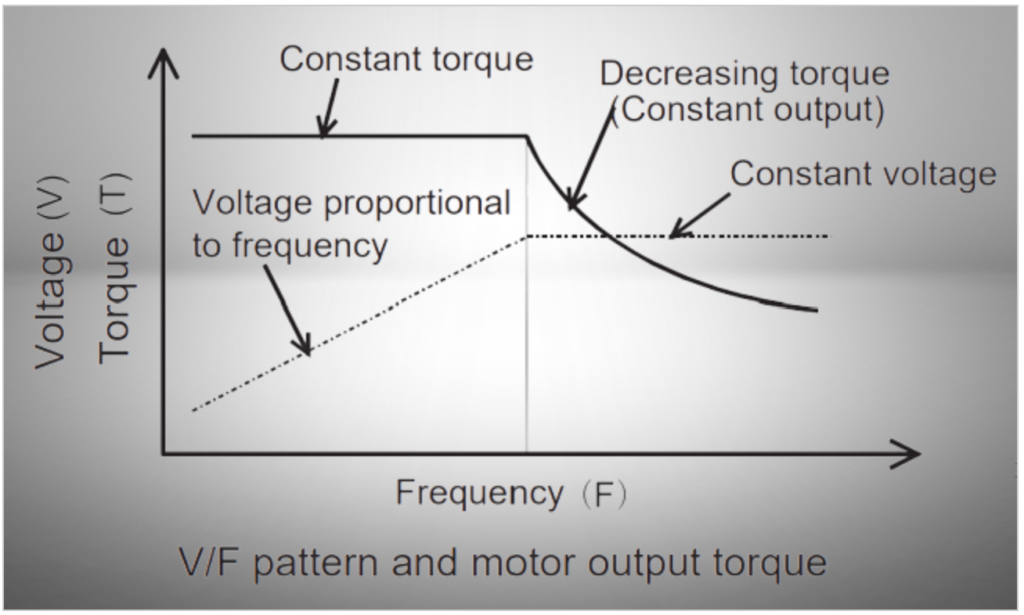
The V/F pattern is a critical concept in motor control. It ensures that the voltage and frequency supplied to the motor are adjusted appropriately to maintain performance and prevent damage, particularly when changing the motor’s speed. This control method is fundamental in various industrial and commercial applications where precise motor speed control is necessary for efficient and safe operation.
Regenerative Brake in Inverter
A regenerative brake is a crucial component in systems where motors can operate in generator mode, converting excess mechanical energy back into electrical energy. This is especially useful when the motor’s speed exceeds the inverter’s output frequency, as in the case of an elevator moving downward.
Here’s how a regenerative brake works and why it’s necessary:

1. Regeneration Process: When a motor operates as a generator, it generates electricity (energy) that needs to be managed. This process is called “regeneration.”
2. DC Voltage Increase: As the motor generates electricity, it returns to the inverter, which typically operates on direct current (DC). This incoming electrical energy increases the DC voltage within the inverter.
3. Voltage Protection: To protect the inverter’s components, particularly the rectifying diodes or IGBT (Insulated Gate Bipolar Transistor), from damage due to an excessive DC voltage, a preventive mechanism is required.
4. Regenerative Brake Resistor: To prevent the DC voltage from exceeding a specified value (e.g., 370VDC for a 200V class inverter), a regenerative brake resistor is inserted in series within the DC voltage circuit, typically between the positive (P) and negative (N) terminals. This resistor serves as a load that consumes excess electrical energy in the form of heat. When the DC voltage surpasses the specified level, the power transistor is turned on, allowing the current to flow through the resistor, where it’s dissipated as heat.
5. Regenerative Brake Capacitor: In addition to the regenerative brake resistor, a power capacitor is often included in parallel to ensure stable operation. This capacitor helps manage the energy flow and provides additional voltage stabilization.
6. Large Capacity Inverters: For larger capacity inverters that require substantial regenerative brake resistors, a power return system is sometimes employed. This system allows the excess regenerative energy to be returned to the power supply side, preventing the generation of excessive heat in the resistor and minimizing its impact on the environment.
As a result, regenerative brake is a critical component in systems where motors can operate as generators. It helps manage excess electrical energy, protect inverter components from voltage surges, and ensures the safe and efficient operation of machinery. By dissipating excess energy as heat through the regenerative brake resistor and capacitors, the system can effectively control and harness regenerative energy, improving overall energy efficiency and preventing damage to the equipment.
Inverter Controlling Methods:
Here’s a concise table summarizing the key differences between a general-purpose inverter and a vector inverter:
| Aspect | General-Purpose Inverter | Vector Inverter |
|---|---|---|
| Output Power Range | 100W to 560kW | 1.5kW to 250kW |
| Transmission Gear Ratio | 1:10 to 1:200 | 1:1000 to 1:1500 |
| Speed Fluctuation (%) | 3-4% (1% or less with advanced control) | 0.03% (Load fluctuation between 0-100%) |
| Frequency Response | Low (1-19Hz) | High (30-125Hz) |
| Start/Stop Frequency | Approx. 15 times/min. | Approx. 100 times/min. |
| Positioning Accuracy | Approx. 1-5mm | 10μm to 100μm |
| Torque Characteristics | Constant torque up to base frequency | Constant torque (0 to rated speed) |
| Applied Motor | General-purpose motor (Induction motor) | Dedicated motor with encoder |
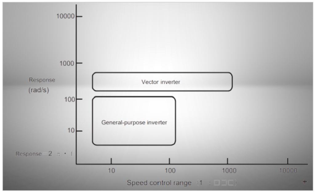
These differences highlight that while both general-purpose and vector inverters share a similar main circuit, they are designed for different applications and offer varying levels of precision and control. General-purpose inverters are suitable for a wide range of applications, whereas vector inverters are tailored for more demanding scenarios that require higher accuracy and performance. The presence or absence of an encoder is a key factor that distinguishes their capabilities.
Inverter control methods play a crucial role in managing the operation of electric motors. Here, we’ll explain into the three primary control methods used with inverters:
1. Speed control Methods
In the context of inverter-based motor control, speed control methods play a vital role in achieving the desired motor speed. There are two primary approaches to speed control:
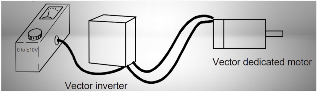
1. Speed Control – Open Loop:
- Open-loop speed control does not involve feedback of the motor’s actual speed to the control system. Instead, it relies on an analog voltage command to set the desired speed.
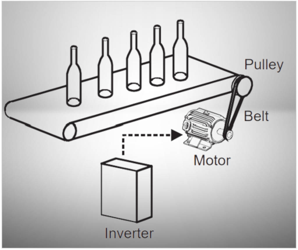
- Applications: This control method is commonly used in various applications such as conveyor speed control, fan wind amount control, pump flow amount control, and others where moderate speed accuracy is acceptable. However, it’s important to note that the actual speed may vary due to factors like motor characteristics, resulting in approximately 3% to 5% speed fluctuation.
- Recent Advances: Modern inverters have improved digital control capabilities that enhance temperature drift resistance. These advancements allow for internal speed data setting and digital command inputs (such as pulse trains, parallel data, and communication). Inverters with advanced control techniques like magnetic flux vector control or real sensorless vector control can achieve speed fluctuations of 1% or less, making them suitable for applications requiring higher precision.
2. Speed Control – Closed Loop:
- Description: Closed-loop speed control involves feedback from the motor’s actual speed, which is detected by an encoder. This feedback allows for precise control of the motor’s speed.
- Feedback Devices: Various devices like tachogenerators (TG) or encoders are used to detect the motor’s speed accurately. Encoders are the most common choice in contemporary applications.
- Control Command: Similar to open-loop control, closed-loop control can use analog voltage or current for speed command. However, it can achieve high-precision speed control by utilizing digital input methods such as pulse trains or digital signals.
- Applications: Closed-loop control is employed when extremely precise speed control is required. It is essential in applications like CNC machines, robotics, and processes where maintaining a specific and consistent speed is critical.
In summary, the choice between open-loop and closed-loop speed control methods depends on the level of speed accuracy needed for a particular application. Open-loop control is suitable for general-purpose applications with moderate speed fluctuations, while closed-loop control, with the use of encoders and digital inputs, provides the highest level of speed precision and is used in applications where accuracy is paramount.
2. Position control methods
Position control methods are essential for applications where precise control of the motor’s position or angle is required. These methods enable the motor not only to control speed but also to stop at a specific target position accurately. There are different approaches to position control:
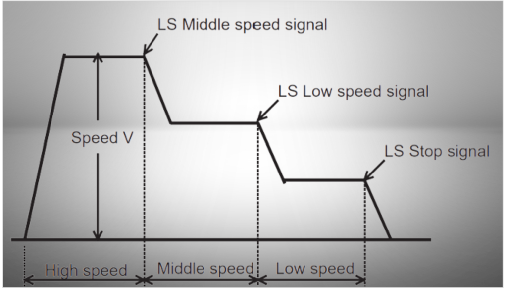
1. Position Control – Open Loop:
- Open-loop position control is employed when high position accuracy is not critical. It relies on external sensor signals or limit switches to stop the motor at the target position. The motor decelerates and stops based on signals from these limit switches, typically located before the target position. While this method is simple, it may have some accuracy limitations due to fluctuations in deceleration points.
- Applications: Open-loop position control is suitable for applications where precise positioning is not essential, and moderate accuracy is acceptable.
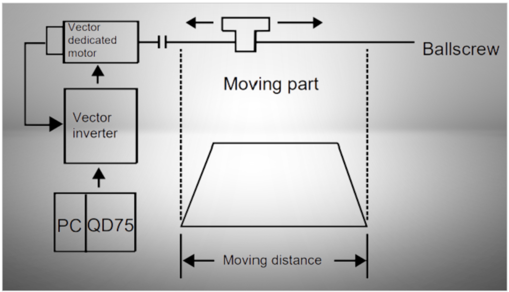
2. Position Control – Semi-Closed Loop:
- Description: Semi-closed loop position control utilizes feedback from an encoder installed on the motor. In this method, a dedicated motor, often designed for vector control, operates based on input commands to a vector inverter. Feedback from the encoder is looped back to the control system, allowing for precise control of the motor’s position and speed. The control system calculates the speed command to minimize the difference between the input command and the feedback amount, ensuring accurate positioning.
- Applications: Semi-closed loop control is employed when moderate to high position accuracy is required. It is suitable for applications where feedback from an encoder can enhance positioning precision.
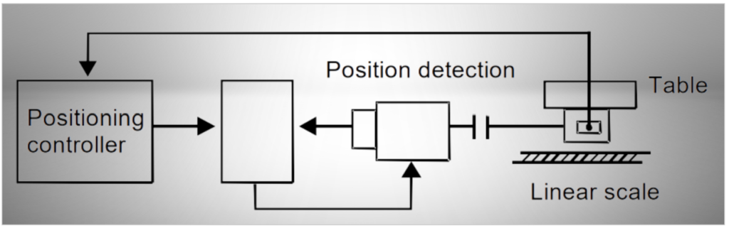
3. Position Control – Full-Closed Loop:
- Description: Full-closed loop position control is the most precise method, relying on feedback from a linear scale or encoder installed on the machine’s side. By installing a linear scale or encoder at the final machine edge, high-accuracy positioning can be achieved, virtually free from errors associated with backlashes or mechanical system imperfections. However, it necessitates a high level of machine rigidity to ensure accurate positioning.
- Applications: Full-closed loop control is typically used in applications where the highest level of precision and accuracy is essential, such as machine tools, where even small positioning errors are unacceptable.
In summary, the choice between open-loop, semi-closed loop, and full-closed loop position control methods depends on the level of accuracy required for a particular application. Open-loop control is suitable for applications where moderate accuracy is acceptable, semi-closed loop control is used when moderate to high accuracy is needed, and full-closed loop control is employed in applications demanding the highest level of precision and accuracy.
3. Torque control Methods
Torque control is a critical aspect of motor control, focusing on regulating the torque or current output from a motor. It should be distinguished from torque limiting, as both methods have their specific applications. Here, we’ll delve into torque control and its different approaches:
Torque Control:
Torque control involves managing the torque (current) output from a motor to achieve specific torque command values. In torque control, the motor’s speed automatically increases when the load torque is smaller than the commanded torque, and it decreases when the load torque exceeds the commanded torque. When the load torque matches the commanded torque, both values are balanced, and the motor comes to a stop. It operates on a principle similar to a tug of war, where the motor’s torque output is adjusted to match the desired level.
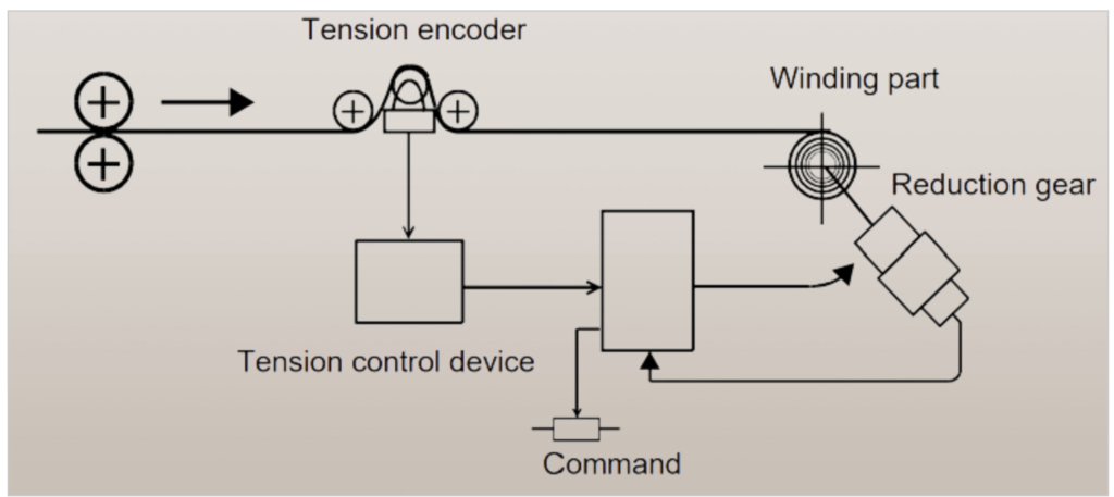
Applications: Torque control is typically used in applications where precise control of torque is required, such as unwinding or winding processes, where maintaining a consistent tension or torque on materials like paper or film is critical.
1. Torque Control – Open Loop:
- Description: Open-loop torque control is used when high torque accuracy is not essential. This method often employs analog torque commands and is suitable for applications like unwinding or winding axes. However, it’s important to note that the accuracy of torque control, especially concerning temperature drift and machine losses, may vary with changing conditions.
- Applications: Open-loop torque control is employed in scenarios where moderate torque accuracy is acceptable, and stringent precision is not required.

2. Torque Control – Closed Loop:
- Description: Closed-loop torque control is used in applications that demand high precision and accuracy in torque control, such as unwinding or winding axes for materials like paper or film. This method incorporates feedback mechanisms to ensure that the tension applied to the actual products matches the desired tension, providing precise control of torque.
- Applications: Closed-loop torque control is employed when maintaining high tension accuracy is crucial for the quality of the final product, as in the case of paper or film processing.
In summary, torque control is crucial in applications where precise control of torque or tension is required. The choice between open-loop and closed-loop torque control methods depends on the desired level of accuracy and the specific requirements of the application. Open-loop torque control is suitable for scenarios with moderate torque accuracy requirements, while closed-loop torque control is employed in applications demanding the highest level of precision and control over torque output.