The Physical Downlink Control Channel (PDCCH) is crucial in 5G NR (New Radio) for transmitting Downlink Control Information (DCI) to one or more User Equipment (UE). This article details the functions, structure, and mechanisms of the PDCCH.
Functions of PDCCH 5G NR.
1. Resource Allocation:
Defines the allocation of resources, modulation, and coding schemes for data on the Physical Downlink Shared Channel (PDSCH) and Physical Uplink Shared Channel (PUSCH).
2. Power Control:
Controls the transmission power for the Physical Uplink Control Channel (PUCCH) and PUSCH.
Structure of PDCCH.
CORESET (Control Resource Set):
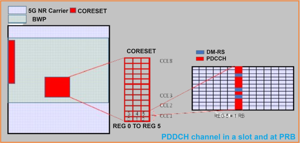
- The PDCCH is transmitted within a grouping of time-frequency resources known as CORESET.
- CORESET is an aggregation of Control Channel Elements (CCE).
- Each CCE consists of six Resource Element Groups (REG), with each REG corresponding to a Resource Block (RB) on an OFDM symbol.
- A CCE contains 72 Resource Elements (REs), of which 18 REs are used for the Demodulation Reference Signals (DM-RS) and 54 REs are for the PDCCH.
- QPSK modulation is used for encoding each symbol.
- REGs forming a CCE can be interleaved to provide frequency diversity.
Frequency and Time Domain:
- In the frequency domain, the CORESET consists of
and is defined by the
CORESET-freq-domparameter, which is transmitted to the UE by RRC signaling. - In the time domain, CORESET is spread over
symbols and it is defined by the
CORESET-time-durparameter. - CORESET is formed by number of REG and is defined by the
parameter.
- Unlike LTE PDCCH, the NR-PDCCH is not transmitted over the entire frequency band but in a BWP sub-partition, similar to the LTE E-PDCCH.

Aggregation:
- The PDCCH and associated DM-RS are transmitted in aggregations of contiguous CCEs, defined by the
aggregation levelparameter (1, 2, 4, 8, or 16 aggregations). - The number of bits that can be transmitted depends on the aggregation level (e.g., 108, 216, 432, 864, 1728 bits for 1, 2, 4, 8, or 16 CCEs respectively). Formula for calculation is 54 RE x 2 bits x Aggregation level.

Search Space and Blind Decoding.
- Search Space:
- The search space is a subset of resource elements within CORESET that the UE scans for DCI intended for it.
- There are two types of search space:
- Common Search Space (CSS): Scanned by all UEs for common control information.
- UE Search Space (USS, Specific Search Space): Dedicated to individual UEs for specific control information.
RNTIs (Radio Network Temporary Identifiers).
RNTIs are 16-bit identifiers used in LTE and 5G NR to distinguish control information dedicated to specific UEs or groups of UEs. The value and type of RNTI determine its specific use.

Types of RNTIs and Their Uses:
- C-RNTI (Cell RNTI):
- Identifies RRC connections and scheduling for specific UEs.
- Used to allocate uplink grants, downlink assignments, etc.
- Differentiates uplink transmissions (PUSCH, PUCCH) of a UE.
- CS-RNTI (Configured Scheduling RNTI):
- Similar to C-RNTI but specifically for configured scheduling.
- SI-RNTI (System Information RNTI):
- Used to broadcast system information blocks (SIB).
- Acts like a broadcast RNTI with the value 0xFFFF.
- P-RNTI (Paging RNTI):
- Broadcasts paging notifications.
- Acts like a broadcast RNTI with the value 0xFFFE.
- RA-RNTI (Random Access RNTI):
- Used during the random access procedure to retrieve transmitted information.
- TC-RNTI (Temporary Cell RNTI):
- Used in the random access procedure to resolve contention.
- TCP-RNTI (Transmit Power Control RNTI):
- Used for uplink control power.
- Types include:
- TCP-PUSCH-RNTI: For PUSCH traffic channels.
- TCP-PUCCH-RNTI: For PUCCH control.
- TCP-SRS-RNTI: For SRS reference signal.
- SP-CSI-RNTI (Semi-Persistent CSI Reporting RNTI):
- Enables or disables resending of CSI measurements on the PUSCH.
- SFI-RNTI (Slot Format Indicator RNTI):
- Notifies the transmission format (DL, UL, or flexible) of a slot for one or more UEs.
- MCS-C-RNTI (Modulation Coding Scheme RNTI):
- Configures the coding and modulation scheme for unicast IP data dynamically.
- INT-RNTI (Interrupt RNTI):
- Notifies the mobile of resource preemption.
DCI Formats of PDCCH 5G NR.
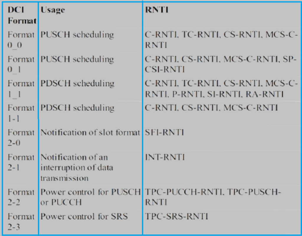
DCI (Downlink Control Information) formats define how resources are allocated and managed. Different formats cater to various types of allocations and control mechanisms:
- DCI Formats 0-0 and 0-1:
- Allocate resources for the PUSCH channel.
- Format 0-0: A standard fallback format for common resource allocation.
- Format 0-1: Used for specific terminal configurations.
- DCI Format 1-0:
- Allocates resources for the PDSCH channel.
- Includes information related to random access, paging, and MIB system information.
- Limited to common characteristics for PDSCH resource allocation.
- DCI Format 1-1:
- Allocates all resources for the PDSCH channel.
- The message size varies with the complete configuration (e.g., carrier aggregation).
- DCI Format 2-0:
- Allows dynamic allocation for a set of terminals by configuring SFI slot directions.
- DCI Format 2-1:
- Manages dynamic preemption of initially allocated resources due to interruptions for priority mobiles.
- DCI Formats 2-2 and 2-3:
- Used for power control of PUSCH/PUCCH and SRS channels, respectively.
Search Spaces and Blind Decoding.
- Search Space:
- A subset of resource elements within the CORESET that UEs scan for DCI messages.
- Two types of search spaces:
- Common Search Space (CSS): Scanned by all UEs for common control information.
- UE Search Space (USS): Dedicated to individual UEs, indicated by RRC signaling.
- Blind Decoding:
- UEs perform blind searches within their search space to decode DCI messages scrambled with RNTI.
- Reduces the number of blind decodings by using fixed CCE sizes and specific aggregation levels.
Understanding these aspects of RNTIs and DCI formats is essential for efficient resource management and communication in LTE and NR networks.