PDCCH stands for Physical Downlink Control Channel (PDCCH) in LTE.
The Physical Downlink Control Channel (PDCCH) plays a key role in LTE by carrying essential control information necessary for both downlink (DL) and uplink (UL) transmissions. The main uses of PDCCH include:
- Downlink Scheduling Assignments: It provides resource indication for the Physical Downlink Shared Channel (PDSCH), transport format, Hybrid Automatic Repeat Request (HARQ) information, transport block size, Multiple Input Multiple Output (MIMO) control information (if applicable), and Physical Uplink Control Channel (PUCCH) power control commands.
- Uplink Scheduling Grants: It provides resource indication for the Physical Uplink Shared Channel (PUSCH), transport format, HARQ-related information, and PUSCH power control commands.
- Power Control Commands: It issues power control commands to groups of terminals, complementing the power control commands embedded within scheduling decisions.
Read Also: What is PDCCH in 5G NR?
Physical Downlink Control Channel (PDCCH) in LTE.
Each PDCCH can carry one of the above messages, and since multiple mobile terminals can be scheduled simultaneously in both the downlink and uplink, there must be a way to transmit multiple scheduling messages within each subframe. Consequently, multiple PDCCHs are typically present in each cell, with each terminal monitoring several PDCCHs.
The payload sizes of the different scheduling messages vary. For instance, supporting spatial multiplexing with non-contiguous allocation of resource blocks in the frequency domain requires a larger scheduling message compared to an uplink grant supporting frequency-contiguous allocations only. Link adaptation is also supported, which matches the code rate of the error-correcting code of the PDCCH to the instantaneous radio conditions. As a result, multiple PDCCH formats are defined by payload size and code rate.
The processing of the PDCCH involves attaching a Cyclic Redundancy Check (CRC) to each PDCCH payload, where the MAC ID (RNTI) is included in the CRC calculation. Upon reception, the terminal checks the CRC using its own RNTI. If the CRC checks out, the message is declared correctly received and intended for the terminal, implicitly encoding the terminal’s identity in the CRC.
After CRC attachment, the PDCCH undergoes channel coding with tail-biting convolutional codes, rate matching, and Quadrature Phase Shift Keying (QPSK) modulation. Depending on the PDCCH message size and channel coding rate (including rate matching), the coded PDCCH size corresponds to 1, 2, 4, or 8 control-channel elements (CCEs). Each CCE corresponds to 36 resource elements or 9 Resource Element Groups (REGs).

Processing of PDCCH:
- Multiplexing and Mapping: Coded and modulated PDCCHs are multiplexed, meaning control-channel elements (CCEs) for the first PDCCH are followed by those for the second, and so on. The multiplexed CCEs are then mapped to resource elements through interleaving groups of four QPSK symbols followed by a cell-specific cyclic shift. This mapping helps in supporting different transmission diversity schemes and randomizes the allocation between cells.
- Resource Elements: The resource elements not used for PCFICH, PHICH, or reference signals in the control region are used for PDCCH transmission. The mapping ensures each CCE spans all OFDM symbols in the control region, promoting even power distribution and flexible power control.
- Power Control: Each PDCCH’s transmission power is controlled by the eNodeB, which can adjust power levels as a complementary link adaptation mechanism alongside adjusting the code rate. This avoids large power differences between PDCCHs, which could complicate RF implementation.
Handling Unused PDCCHs:
Dummy PDCCHs: If not all possible PDCCHs are used in a control region, the unused ones are treated the same way as others during interleaving and mapping but fail CRC checks, meaning no UE detects them. Typically, these dummy PDCCHs are set to zero power to save resources.

Formats and Blind Decoding:
- Multiple Formats: Each PDCCH supports multiple formats, and terminals must blindly detect the format of the received PDCCHs. To reduce the number of blind decoding attempts, 3GPP has defined four different PDCCH formats and allows CCE aggregation in sizes of 1, 2, 4, or 8.
- Search Spaces: To speed up PDCCH decoding, there are UE-specific and common search spaces, which help terminals quickly locate their designated control information.
| PDCCH Format | Number of CCEs | Number of REGs | Number of PDCCH bits |
| 0 | 1 | 9 | 72 |
| 1 | 2 | 18 | 144 |
| 2 | 4 | 36 | 288 |
| 3 | 8 | 72 | 576 |

Downlink Scheduling Assignments.
In LTE, downlink scheduling assignments are crucial for managing resource allocation and ensuring efficient communication. These assignments provide information such as resource block (RB) indication, modulation and transport-block size, hybrid-ARQ details, PUCCH power control commands, and spatial multiplexing information if applicable.
Resource Block Indications:
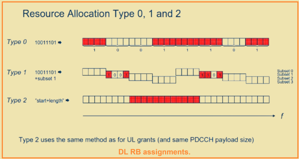
- Type 0 and 1: Use bitmaps to support non-contiguous allocations in the frequency domain. Type 0 represents groups of contiguous RBs (group size depends on system bandwidth) to reduce bitmap size. Type 1 divides RBs into subsets, with a bitmap indicating the RBs used within the subset.
- Type 2: Uses a Resource Indication Value (RIV) to indicate the start and length of virtually contiguous RBs.
Downlink Control Information (DCI):
- DCI 0: For uplink scheduling, uses an allocation type similar to type 2.
- DCI 1, 2, and 2A: Use type 0 (bitmap) for downlink allocation.
- DCI 1: For transmission diversity.
- DCI 2: For closed-loop spatial multiplexing.
- DCI 2A: For open-loop spatial multiplexing.
- DCI 1A: Uses type 2 (RIV) for compact scheduling, indicating the start and length of the RB allocation.
- DCI 1B, 1C, and 1D: Differ in the amount of information included in the scheduling assignment.

Message Contents:
- The downlink scheduling assignments are transmitted to the user equipment (UE) via the PDCCH. The specific DCI format used depends on the type of scheduling required and the downlink system bandwidth.
- Each DCI format supports various scheduling tasks, ensuring efficient and flexible resource management.
Example – DCI Format 1A:
- Compact Scheduling: Used for efficient allocation of resources when scheduling a single code word, ensuring minimal overhead and quick scheduling decisions.

Power Control Commands.
n LTE, power control is essential for maintaining optimal signal quality and reducing interference. To complement the power control commands included in downlink and uplink scheduling assignments, additional power control commands can be transmitted using DCI format 3 and 3A.
DCI Format 3 and 3A:
- Group Identity: The power control message is directed to a group of terminals, identified by a group identity.
- Individual Control: Despite being sent to a group, each terminal within the group has two bits reserved for its power control commands. This allows for individual power adjustments for each terminal in the group.