Ship Lines Plan
Hull line drawings are essential in naval architecture for visualizing the shape of a ship’s hull. These drawings are created by intersecting the hull with a series of equally spaced planes in three dimensions. Here’s a breakdown of the key aspects of hull line drawings:
- Orthogonal Planes: The planes used for intersecting the hull are arranged in three dimensions, with sets of planes perpendicular to each other. This arrangement ensures that the lines generated by the intersection provide comprehensive coverage of the hull’s shape.
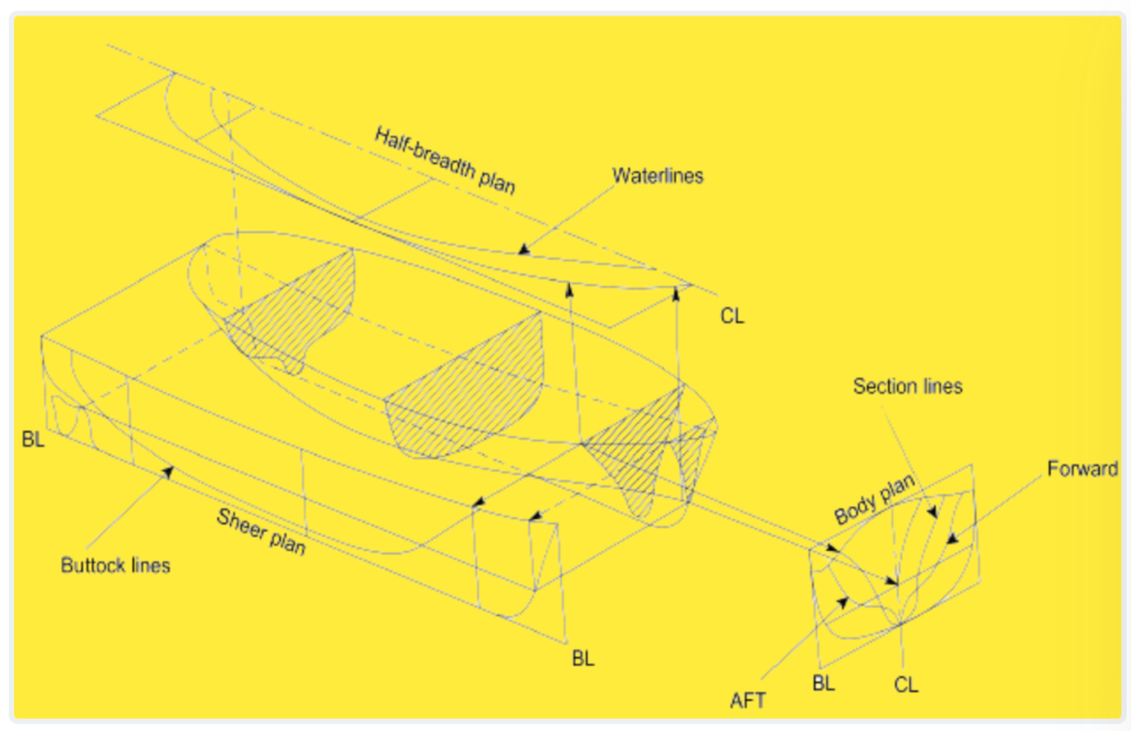
- Projection Views: The points of intersection between the hull and the orthogonal planes result in lines that are projected onto a single plane located on the bow, deck, or side shell of the ship. These projections create three separate views known as the Body plan, Half-Breadth plan, and Sheer plan (or Profile).
- Body Plan: This view represents the shape of the hull as seen when looking at it from the front or rear. It shows the cross-sections of the hull at various frame stations along its length, providing insights into the curvature and tapering of the hull.
- Half-Breadth Plan: This view illustrates the shape of the hull as seen from above, looking down onto the waterline. It displays the hull’s cross-sections at different waterlines, allowing designers to understand how the shape changes with changes in draft.
- Sheer Plan (Profile): This view presents the side profile of the ship, showing the curvature of the hull from bow to stern. It highlights the sheer line (the curvature of the deck) and the shape of the stem and stern.
- Idealization: The drawings typically depict an idealized representation of a classic mono-hull design, which is symmetric about the longitudinal plane. While real-world hulls may exhibit variations and asymmetries, these drawings provide a standardized reference for analysis and visualization.
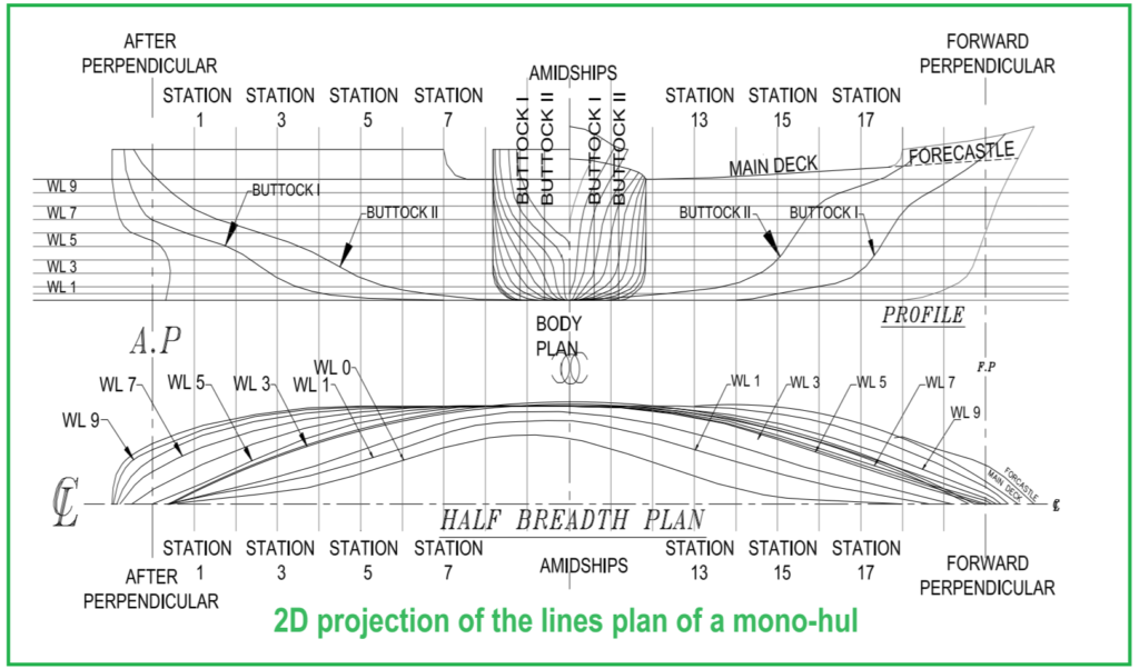
By examining these hull line drawings, naval architects and ship designers can gain valuable insights into the shape and form of the hull, enabling them to make informed decisions during the design and construction process.
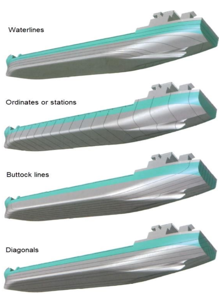
Waterlines and Half Breadth Plan
In naval architecture, the intersection of horizontal planes with the shape of the hull results in lines known as waterlines. These waterlines represent the true shape of the hull from a top view at various elevations above the base plane or keel. When depicted in the hull lines drawing, this view is called the half-breadth plan because only half of the ship is typically drawn, mirroring its symmetrical nature along the longitudinal plane.
Each waterline in the half-breadth plan serves as a pattern for the construction of the ship’s framing, providing crucial information about the curvature and tapering of the hull at different levels.
Additionally, the lines formed by the intersection of planes parallel to the middle line longitudinal plane are referred to as buttocks. These buttock lines run longitudinally along the hull and provide insights into its shape when viewed from the side.
What is Profile in Marine Engineering?
Furthermore, the line of intersection between the hull and the middle line plane is known as the profile. This line represents the side profile of the ship, capturing its curvature from bow to stern. Together, waterlines, buttocks, and the profile contribute to a comprehensive understanding of the hull’s shape and form, aiding in the design and construction process.
Buttock Line
In naval architecture, each buttock line represents the true shape of the hull from a side view at a specific distance from the centerline of the ship. These buttock lines are essential for constructing the ship’s longitudinal framing, providing a guide for shaping the hull’s curvature along its length.
Sheer Profile
The overall side view of the ship, which encompasses the buttock lines and other features, is referred to as the sheer profile. This profile offers a comprehensive depiction of the ship’s outline and curvature when viewed from the side.
Stations
Additionally, the lines formed by the intersection of transverse planes with the hull are called stations. These stations are evenly spaced along the length of the ship and are represented on the body plan view. Stations play a crucial role in defining the shape and form of the ship’s cross-sections at various points along its length.
Furthermore, each sectional line represents the true shape of the hull from a front view at a specific longitudinal position on the ship. These sectional lines serve as templates for constructing the ship’s transverse framing, providing guidance on the curvature and shape of the hull when viewed from the front.
To facilitate the construction process, a series of planes parallel to one side of the centerline plane are imagined at regular intervals from the centerline. These planes help in visualizing and defining the transverse framing of the ship, ensuring consistency and accuracy in the construction of its structural components.