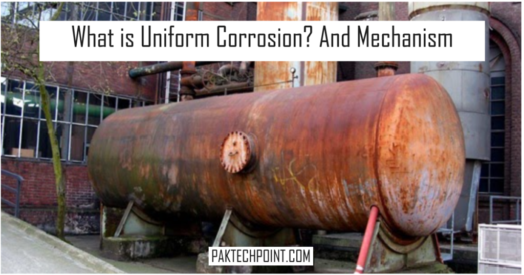
Uniform corrosion, also known as general corrosion, is the most common type of corrosion and refers to the gradual and relatively uniform deterioration of a metal surface over time. In uniform corrosion, the metal corrodes uniformly across its entire surface area, resulting in a consistent loss of material thickness. This type of corrosion typically occurs when a metal is exposed to a corrosive environment, such as moisture, oxygen, or chemical agents, for an extended period.
Below picture is showing actual uniform corrosion diagram.

Uniform Corrosion Explanation.
The uniform or general corrosion is thinning/wall loss involving wider areas rather than being scattered/isolated pits with undamaged areas around. The attack is relatively evenly distributed over large area of affected metal.
It is believed that In uniform corrosion mechanism, the local corrosion cells (anodes and cathodes) are not locked in one position on the metal surface. Rather the location of corrosion cells moves around randomly, causing a general dissociation of the metallic atoms (in from of ionic salts) from a wider area. The uniform corrosion could be the even washout of the surface or large concentration of the pitting, making the rough surface.
The general corrosion effects almost entire process system which is not lined by the protective coating, however the rate of corrosion phases out gradually due to formation of the oxide or sulfide layer, which act as protective barrier for further corrosion.
However in most of the cases where the turbulent or high speed process fluid flow is involved, the protective layer is washed out and the corrosion of the impact area continues. This induces the accelerated localized corrosion also known as erosion corrosion.
What are reasons behind uniform corrosion?
Two main reasons behind the general / uniform corrosion wall loss are
- The material involved is not able to maintain the protective coating which can isolate the metal from environment.
- The concentration of the electrolyte does not vary significantly over the metal surface, so anodic and the cathodic reaction both occur in a wider area rather than being concentrated in isolated locations.
Any damage mechanism that carries both of these properties will be the contributing factor behind uniform corrosion. For carbon steal the process streams containing the acidic and alkaline compounds are the main causes of the generalized corrosion.
Hence wherever such ingredients are found in the process streams the inspector should expect the aggressive generalized wall loss. However, depending on the conditions, the mechanisms responsible for the generalized corrosion can also cause the localized pitting corrosion.
Uniform Corrosion Mechanism.
Some of the prominent damage mechanisms which can be grouped as uniform or generalized corrosion mechanisms are listed below.
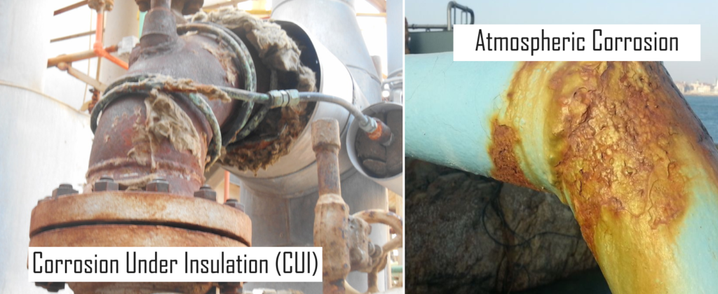
1. Atmospheric Corrosion & Corrosion Under Insulation (CUI).
Atmospheric corrosion and corrosion under insulation & Fire Proofing are treated as two different categories of corrosion in API‐571, however because of same origin and same governing condition both are discussed together in this article.
The atmospheric conditions including the natural marine environment and air born industrial pollutant like H2S and fly ash containing sulfur and chloride salts, cause the external corrosion of the equipment which are not effectively protected by the protective coating. For Carbon Steel this corrosion is active between ‐4oC to 120o C, and aggressive at the temperatures between 100o C to 120o C.

Outside this temperature range the surface of the equipment is usually too dry for oxidation. Most critical are the insulated equipment, as insulation has the tendency to trap the moisture and keep in contact with the metal surface for longer period of time. The broken, missing of damaged insulation cladding are the source of moisture ingress. Similarly the locations like insulation termination ends at the flanges, protrusion of the small bore piping (and tubing) and the TML cutouts and leaking steam tracings are major contributing factors to CUI.
The equipment and piping involved in the chilling services condense substantial amount of moisture. During the shutdown periods the condensation thaws out and moist the insulation which can causes CUI even in the equipment with good cladding with no moisture ingress. For stainless steel grades the chloride stress corrosion cracking is major issue. These chlorides come from the environment or could be within the insulation.
While inspecting for CUI and atmospheric corrosion particular attention should be paid to the location which have potential for trapping the moisture. Some of the examples of such locations are stiffener joints, pipe support saddles, and bottom section of the insulated vessels. The corrosion between the saddles and the piping is also very common which causes the piping failure. Depending on the configuration and restriction for proper aeration, these locations also have tendency to induce the crevice corrosion.
Various NDT techniques are available (along with Visual inspection) for CUI monitoring. These techniques include infrared scanning (for dry/wet insulation spots), neutron back scattering technique, ultrasonic guided wave surveying, and profile radiography. Further details on these damage mechanisms can be seen from API‐RP‐571 Para 4.3.2 and 4.3.3.
2. Rich Amine Corrosion.
Gas sweetening is typically done in the gas plants and the refineries by the amine absorption. The dissolved acidic gases like H2S and CO2 along with some amine salts cause the localized pitting corrosion and the generalized corrosion mainly in the bottom areas of the amine contactor towers downstream piping carrying the rich amine to the stripper tower. The main controlling factors for the corrosion are the concentration of the contaminants in rich amine, flow velocity and the temperature.
However these problems can be controlled with proper design of the system and proper operation practices. Further the types of the Amine absorbent also plays significant role in the amine corrosion. The units using monoethanolamine (MEA), and diglycolamine (DGA) have most problems with amine corrosion. However the units using diethanolamine (DEA), and methyldiethanolamine (MDEA) are relatively better in corrosion resistance. The unit inspector and the corrosion engineer should continuously review the lab reports and monitor the concentration of ammonia and cyanide salts such as HCN.
Most vulnerable locations in amine units are the regenerator overhead condenser and outlet piping as well as reflux piping, valves and pumps. The velocity of the fluids also plays major role so the piping downstream of the pumps, especially at the direction changes and turbulent flow locations must be closely monitored with ultrasonic. Whole system should be saved from oxygen ingress at the time of shutdown as the addition of oxygen aids in creating the heat stable salts in the system which cause sewer corrosion in the system.
The appropriate methods of detection are the profile radiography and ultrasonic scanning at the vulnerable location on the piping. And for the vessels the appropriate methods are the ultrasonic thickness measurement and thorough visual inspection at the shutdowns. Amine stress corrosion cracking is another prominent damage mechanism associated with the carbon steel amine systems. This mechanism is further discussed in Para number 3.1.5 of this section.
Further details on this damage mechanism can be seen from API‐RP‐571 Para 5.1.1.1.
3. Soil Corrosion.
The localized deterioration and corrosion of metal at the areas in contact with soil is called as the soil corrosion. Most of the soil corrosion problems are associated with the buried pipelines. However process plants also have various buried piping tank bottoms and other equipment partially or fully buried in ground, which are prone to deteriorate due to soil corrosion.

Experience has shown that in buried plant piping the most affected areas are the soil to interface. The corrosion in this area is found maximum if the air has higher moisture and salinity. It is recommended to excavate such pipes to at least 12” for proper inspection of Soil to air interface area.
Various factors control the susceptibility of the corrosion on the metallic surfaces in
contact with the soil. These factors include,
- Moisture and oxygen contents in soil.
- Electrical resistivity of soil (amount of electrolytes).
- Homogeneity (mixing of other types of soil and elements).
- Temperature.
- Availability of cathodic protection.
- Stray current currents in the area.
- Integrity and type of the coating on the equipment/piping.
- The corrosion resistivity of the equipment metal.
The soil resistivity measurement should be periodically done, in the areas where the ground water table keeps changing, as per recommendations of API‐RP574 Para 10.3.1.4. The lesser soil resistivity (higher conductivity) is the sign of the imminent corrosion problem.
Other than visual inspection and the pressure testing various on‐stream inspection techniques are available for detection and quantitative measurement of the soil corrosion damage. For pipe lines various inline scrapping techniques are available.
Similarly the guided waves technique is proved good for the buried plant piping. For tanks the acoustic emission measurement can be used to detect the deterioration of the floor due to internal or external (bottom side) soil corrosion.
Further details on this damage mechanism can be seen from API‐RP‐571 Para 4.3.9.
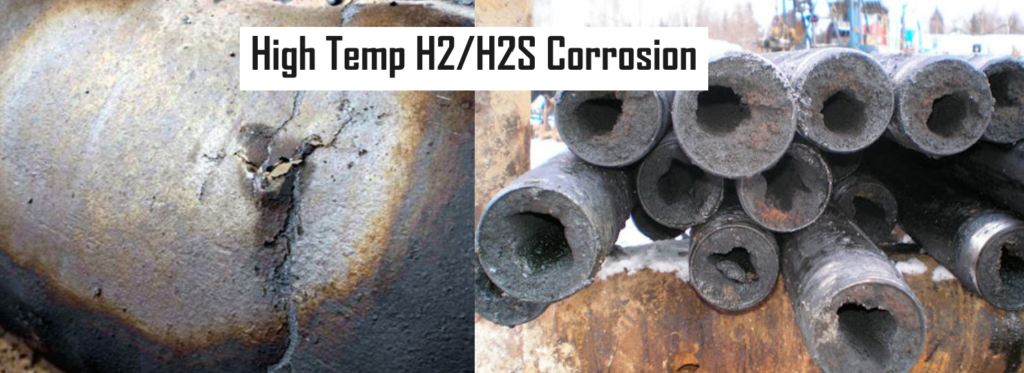
4. High Temp H2/H2S Corrosion.
High temperature H2/H2S a uniform corrosion mechanism predominant in the services which contain significant concentration if H2S at higher temperatures (above 250oC). This is another form of sulfidation attack which appears as generalized wall loss in affected equipment. This form of corrosion occurs in equipment all hydro processing units such desulfurizers, hydro‐treaters and hydro cracking units where process streams carry H2 and H2S at high temperatures. Noticeable increases in corrosion may be found downstream of hydrogen injection points.

Most affected materials are carbon and low alloy steels while 300 and 400 series stainless steel and chromium based alloy steels are relatively immune to this attack. Main controlling factors are the concentration of H2S and the temperature. The attack is aggressive at higher temperature and higher concentrations of H2S.
Further details on this damage mechanism can be seen from API‐RP‐571 Para 5.1.1.5.
Characteristics of Uniform Corrosion:
- Even Loss of Material: Uniform corrosion results in a consistent loss of material thickness across the entire surface of the metal, leading to a uniform appearance of corrosion damage.
- Surface Deterioration: The metal surface may exhibit signs of dullness, discoloration, or roughness as a result of the corrosion process. In severe cases, corrosion products such as rust or scale may form on the surface.
- Predictable Rate: Uniform corrosion typically occurs at a predictable and steady rate, making it relatively easy to anticipate and assess the extent of damage over time.
Prevention and Control:
- Protective Coatings: Applying protective coatings such as paint, varnish, or corrosion-resistant coatings can provide a barrier between the metal surface and the corrosive environment, preventing direct contact and inhibiting corrosion.
- Corrosion Inhibitors: Adding corrosion inhibitors to the environment or incorporating them into the metal surface can help suppress or slow down the corrosion process by interfering with the electrochemical reactions.
- Controlled Environment: Controlling environmental factors such as humidity, temperature, and chemical composition can minimize the risk of uniform corrosion by reducing exposure to corrosive agents.
- Material Selection: Choosing corrosion-resistant metals or alloys for specific applications can significantly reduce the susceptibility to uniform corrosion and extend the service life of components in corrosive environments.
Overall, uniform corrosion is a common and predictable form of corrosion that affects metal surfaces in various industries and applications. Understanding its mechanisms and implementing appropriate preventive measures are essential for mitigating its impact and ensuring the longevity of metal structures and components.