![What is Voltage Transformer? Technical Explanation [PDF]](https://paktechpoint.com/wp-content/uploads/2024/01/image-131-1024x1002.png)
Voltage transformer is also call potential transformer. There are two main types of voltage transformers: magnetic voltage transformers (VT) and capacitive voltage transformers (CVT). Magnetic voltage transformers are more cost-effective for voltages up to around 145 kV, while capacitive voltage transformers are suitable for higher voltages beyond 145 kV. Capacitive voltage transformers can also work alongside Power Line Carrier (PLC) devices, which are used for communication over high-voltage transmission circuits.
Voltage transformers, along with current transformers, are part of a group called instrument transformers. Typically, voltage transformers are connected between the phase and ground in electrical systems. The detailed specifications for voltage transformers are outlined in the IEC 186 standard.
Instrument transformers serve several key functions:
- Transformation of Currents or Voltages:
- Their primary role is to convert high-value currents or voltages into values that can be easily managed by protection relays and instruments. This transformation allows for accurate measurement and monitoring of electrical quantities.
- Insulation of Metering Circuit:
- Instrument transformers provide insulation for the metering circuit, protecting it from the high voltage present in the primary side. This insulation ensures the safety and proper functioning of the measuring instruments.
- Standardization for Instruments and Relays:
- Instrument transformers enable standardization by providing a consistent reference for instruments and protection relays. This standardization is applied to a limited set of rated currents and voltages, streamlining the compatibility and operation of the connected devices.
Instrument transformers, which include transformers for voltage and current measurements, follow engineering principles similar to those used for power transformers. Two equations commonly applied to instrument transformers are:
- Short-Circuited Transformer Equation (1):
I2I1=N1N2
This equation is used for a transformer with a short circuit. - No-Load Transformer Equation (2):
E1/E2=N1/N2
This equation is applied to a transformer operating with no load.
These equations provide a basis for understanding the relationships between primary and secondary currents or voltages under different operating conditions for instrument transformers.
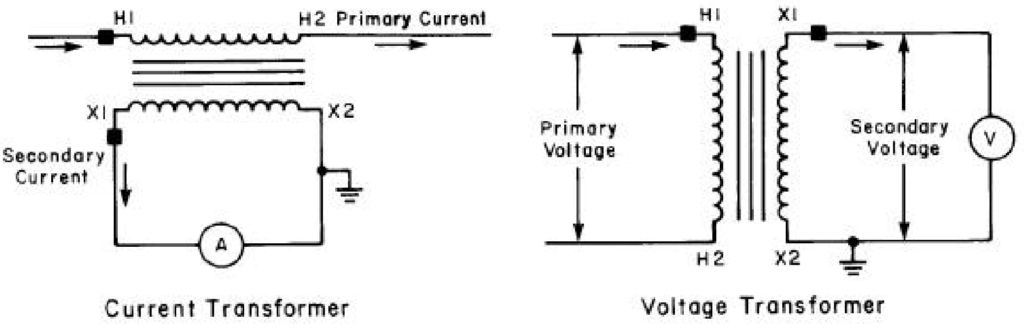
Equation (1) illustrates how the current is transformed in relation to the turns in both the primary and secondary windings. Equation (2) demonstrates the transformation of voltage in proportion to the primary and secondary turns. The operation of a current transformer is rooted in Equation (1), envisioning an ideal scenario where the transformer is short-circuited, resulting in zero secondary terminal voltage and negligible magnetizing current.
Voltage Transformer Working Principle
On the other hand, the operation of a voltage transformer is based on Equation (2), picturing an ideal transformer under no-load conditions where the load current is zero, and the voltage drop is mainly caused by the magnetizing current, which is also negligible. In practical applications, these ideal conditions are not fully met because instrument transformers are typically burdened with loads such as protection relays, instruments, and cables. This introduces measuring errors in both current transformers, due to magnetizing current, and voltage transformers, due to the voltage drop caused by the load current.
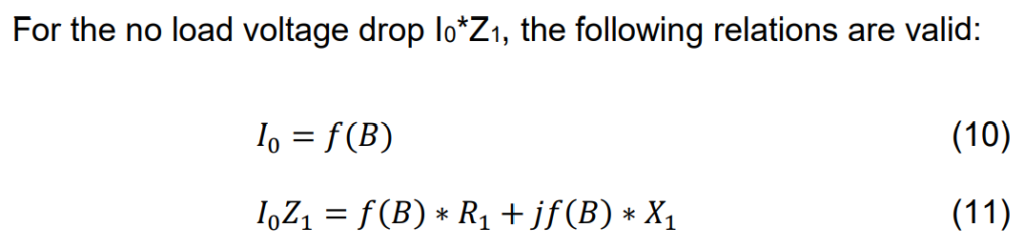
The vector diagram for a single-phase instrument transformer is depicted in Figure 1.
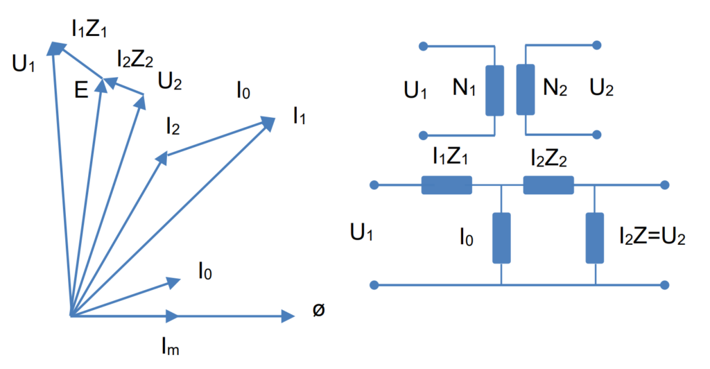
The turn ratio for this particular instrument transformer is simplified to 1:1 for clarity in representation. The primary terminal voltage is denoted as U1. By vectorially subtracting the voltage drop I1Z1 from U1, we obtain the electromagnetic force E. Notably, E is also the vectorial sum of the secondary terminal voltage U1 and the secondary voltage drop I2Z2. The secondary terminal voltage U2 can be expressed as I2Z, where Z represents the burden impedance.
The creation of the electromagnetic force E is attributed to the flux Ø, which lags E by 90°. The flux is induced by the magnetizing current Im, aligning with Ø. Im serves as the reactive component of the no-load current I0 and is in phase with E.
Instrument Transformer Measuring Error
The voltage transformer is commonly subjected to a load presented by impedance, comprising protection relays, instruments, and cables. To generate the required electromagnetic force E for sustaining the secondary current I2 across the entire burden (Z2+Z), a magnetizing current I0 is essential. This magnetizing current is drawn from the primary side voltage. It’s important to note that I0 is not a component of the voltage transformation process. Instead of conforming to the rated ratio Kn:
Equation (3) defines the nominal voltage ratio Kn as:
U1/U2=Nominal ratio Kn
The real voltage ratio Kd is expressed by Equation (4):
U1−ΔU/U2=Real ratio Kd
Here, U1 is the rated voltage of the primary, and U2 is the rated voltage of the secondary.
The measuring error ε, given by Equation (5), is expressed as:
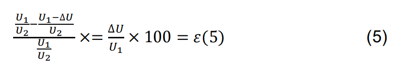
where U1 is the voltage of the primary, and U2 is the voltage of the secondary.
The reproduction error in an instrument transformer manifests in both magnitude and phase. The magnitude error is referred to as voltage or ratio error. In line with this definition, the voltage error is considered positive when the secondary voltage exceeds what the rated voltage ratio would indicate.
On the other hand, the phase angle error is termed phase error or phase displacement. A positive phase error implies that the voltage of the secondary is leading the primary in terms of phase angle.
Hence, the performance of the voltage transformer relies on the voltage U, the flux density, and the magnetizing curve, with some dependence on the load current. The magnetizing current, which contributes to the measurement error, is influenced by various factors, as illustrated in Figure 2. Additionally, the induced electromagnetic force plays a crucial role in determining the transformer’s capacity to handle the burden.
To minimize voltage drop, certain measures can be implemented:
- Use a primary winding with a wire of substantial cross-sectional area.
- Apply low induction in the transformer.
- Keep the reactance at a low level.
This implies the use of a large core cross-sectional area to avoid a high number of primary turns, considering that reactance has a square dependence on the number of turns. The load-dependent voltage drop, I2Zk, is quantified by Equation (12).
current
To minimize voltage drop caused by the load current, it is essential to maintain low impedances in both the primary and secondary. In practical terms, this involves using windings with substantial cross-sectional areas for the wires and designing the coils to be as compact as possible. This compact design helps reduce leakage flux, ensuring efficient performance and minimizing the impact of load currents on the voltage drop.
The measuring error change with the voltage
The no-load error I0Z1 varies with the voltage in accordance with the transformer’s magnetizing curve. The primary impedance Z1 is considered constant. The voltage drop, influenced by the load, is proportional to U2 as I2=U2/Z, where Z is the connected burden, and Z1 and Zk are constants. As a result, the relative voltage drop remains constant.
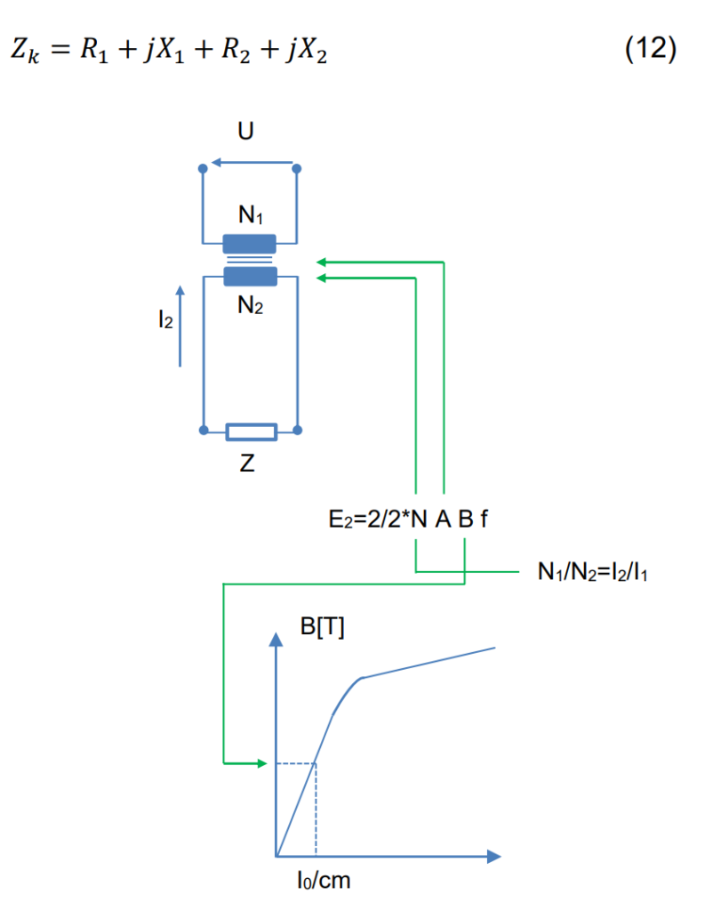
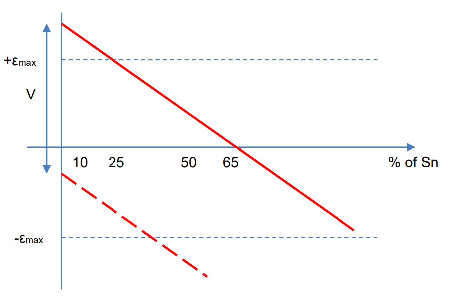
Turns correction is commonly applied to voltage transformers to achieve high accuracy. The increased number of turns allows for precise adjustments in small increments. According to IEC 186 standards, a voltage transformer must meet its accuracy class for burdens ranging from 25% to 100% of the rated burden. Turns correction is typically selected to introduce a positive error (+ϵmax) at 25% of the rated burden and a negative error (−ϵmax) at 100% of the rated burden, as illustrated in Figure 3.
of the primary
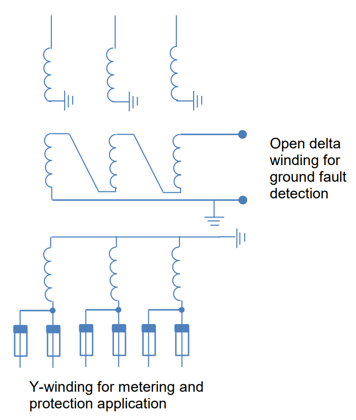
Voltage Transformers with Multiple Secondary Windings
Voltage transformers can be constructed with multiple secondary windings to accommodate various applications. This is useful when different secondary windings are needed for distinct purposes. Each loaded secondary winding draws current from the primary winding, and the overall voltage drop is determined by the sum of the secondary burdens.
A common design includes one Y-connected winding and an additional secondary winding for open delta connection, primarily used for ground fault protection relays. The open delta winding is not loaded during normal operation, ensuring it doesn’t impact measuring accuracy. This winding is typically designed with a 110 V secondary for solidly grounded systems and 110/√3 V for ungrounded, reactance, or resistance grounded systems. This configuration provides an open delta output of 110 V during a solid ground fault in both system types.
one Open delta connected
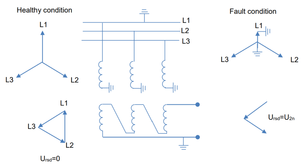
grounded system
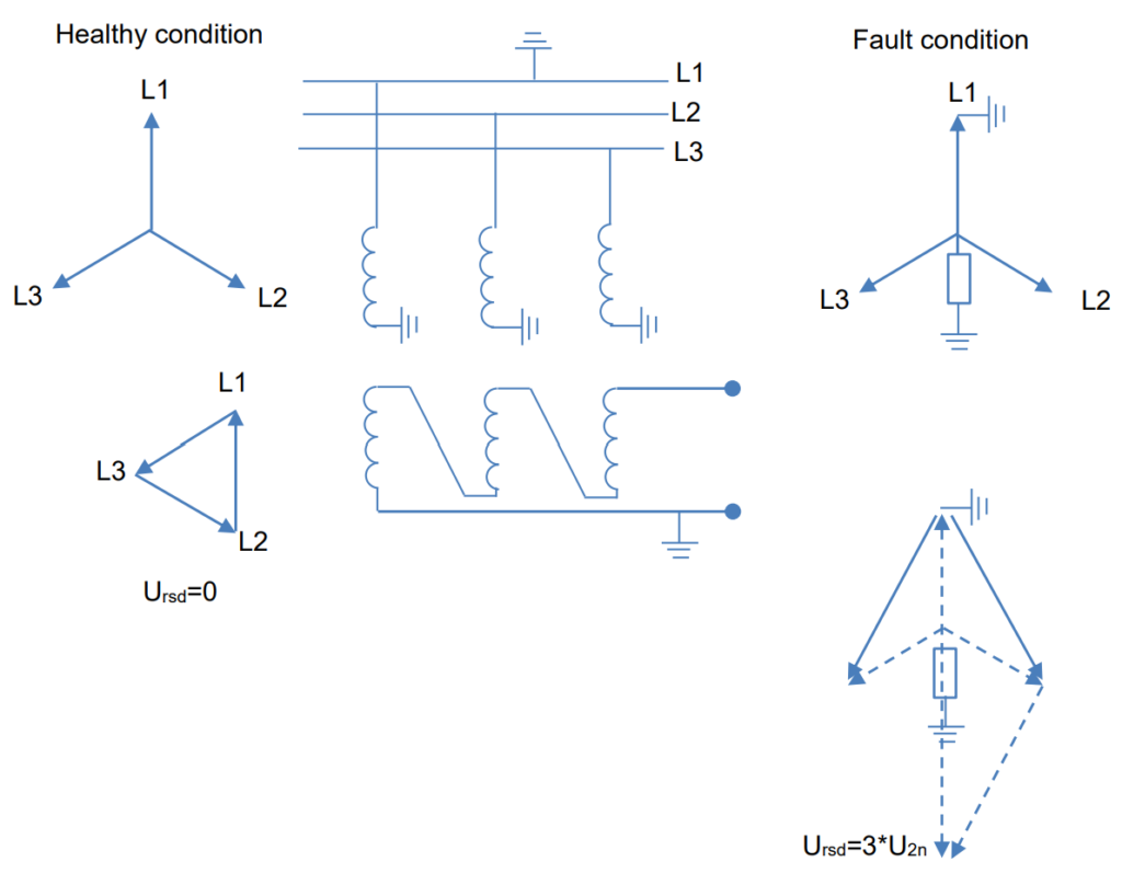
ungrounded or high resistive/resonance grounded system
What is Voltage Factor?
Voltage transformers (VTs) are usually linked between the phase and ground in power systems. In the event of a fault in the network, the voltage across the VTs (or capacitive voltage transformers, CVTs) may escalate in the unaffected phases. The International Electrotechnical Commission (IEC) defines voltage factors: 1.9 for systems without solid grounding and 1.5 for solidly grounded systems.
The saturation time is set at 30 seconds for systems equipped with ground fault protection that can trigger tripping. In cases where no ground fault tripping protection is in place, the saturation time extends to 8 hours. It’s crucial to ensure that the VTs do not reach saturation under the influence of the specified voltage factors.
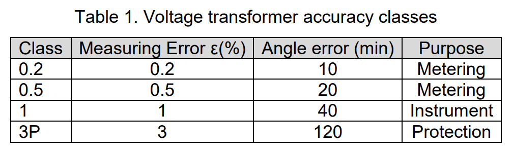
Burden and Accuracy Classes
IEC 186 outlines several standard rated burden values, with preferred burdens being 10, 25, 50, 100, 200, and 500 VA. These values are per phase for a three-phase set, presented for a power factor (cos Ø) of 0.8. The accuracy class is defined for 25-100% of the rated burden. Given the low burden of modern protection and metering equipment (typically in the range of 5-10 VA), and considering that accuracy class fulfillment is down to 25%, applying a low rated burden is advisable.
A rated burden approximately “1.5 x connected burden” maximizes accuracy at the connected burden. Refer to Figure 3 for details. Accuracy classes are established for both protection and metering purposes. Table 1 outlines IEC 186 requirements for ratio and angle error for various classes.
It’s important to note that a voltage transformer winding can have a combined class, such as 0.5/3P. This signifies that metering accuracy is achieved for 80-120% of the nominal voltage, meeting the requirements for 5% of nominal voltage and the transient response requirement from protection cores as well.
Class A Equipment Standard Rated Burdens
The rated burden of the secondary winding is specified in watts (W) at the rated secondary voltage when the rated line-to-ground voltage is applied across the capacitance voltage divider. The total rated burden of the device is the sum of the watt burdens that may be simultaneously applied to both secondary windings.
Adjustment capacitors are integrated into the device to connect in parallel with the burden on one secondary winding. This correction compensates for the overall burden power factor, bringing it to unity or slightly leading. Table 2 presents the standard rated burdens for bushing potential equipment.
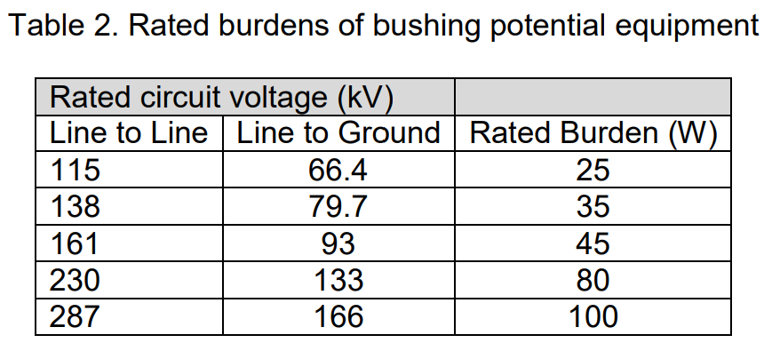
For coupling-capacitor potential devices, the rated burden is standardized at 150 watts for any of the rated circuit voltages, including those listed in Table 2.
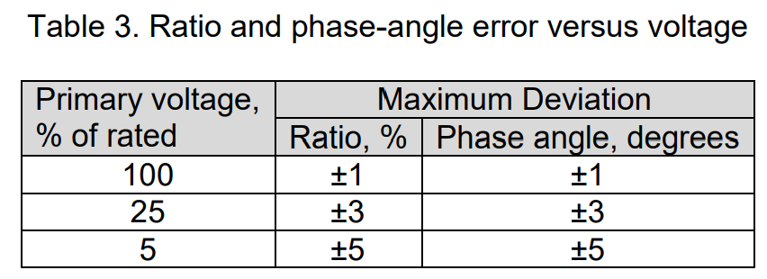
Class A Equipment Standard Accuracy
Table 3 outlines the standard maximum voltage ratio deviation and phase angle for rated burden, considering various primary voltage values. The device is adjusted for the specific accuracy at the rated primary voltage.
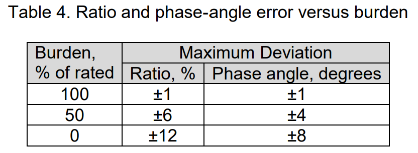
On the other hand, Table 4 displays the standard maximum voltage ratio deviation and phase angle for rated voltage, taking into account different burden values. It’s emphasized that for optimal accuracy, changing the burden without readjusting the device is not advisable, as indicated in Table 4.
Non-Linear Burdens in Voltage Transformer
A “non-linear” burden refers to a burden whose impedance decreases when the applied voltage increases due to magnetic saturation. Significant non-linearity in such a burden can lead to ferroresonance, a condition characterized by steady over-voltages with a highly distorted waveform across the burden. This situation should be avoided, as the resulting voltages bear no resemblance to the primary voltages.
To prevent ferroresonance, it’s crucial to consult with the manufacturer to determine the maximum tolerable degree of non-linearity. Alternatively, ferroresonance can be averted by ensuring that all magnetic circuits within the burden operate at rated voltage with a low flux density. This ensures that any potential momentary overvoltage will not cause the flux density of any magnetic circuit to exceed the knee of its magnetization curve, typically around 100,000 lines per square inch.
As the secondary-winding voltage of the potential device may increase to √3 times rated, and the broken-delta voltage may increase to √3 times rated, the corresponding burdens for line-to-neutral and broken-delta configurations may need to have no more than 1/√3 and 1/3, respectively, of the maximum allowable flux density at rated voltage.
If burdens with closed magnetic circuits, like auxiliary potential transformers, are not installed, there is no chance of ferroresonance. Class A potential equipment is equipped with two secondary windings to eliminate the need for an auxiliary potential transformer. Commonly used protection relays, meters, and instruments often incorporate air gaps in their magnetic circuits or operate at low flux density to ensure the linearity of their burdens.
The Broken-Delta Burden and the Winding Burden
The broken-delta burden seems to involve voltage-polarizing coils of ground directional protection relays, each with a series capacitor to ensure a lagging angle of maximum torque. This configuration results in a leading power factor for the voltage-coil circuit. I find this arrangement intriguing. Could you elaborate on how the interplay between the series capacitor and the relay’s voltage-coil circuit impacts the power factor and overall burden?
It’s also interesting to note that the burden of each protection relay is determined by the manufacturer in relation to the rated voltage of the protection relay. I wonder, does the manufacturer provide specific guidelines or considerations for calculating or optimizing this burden based on the relay’s voltage rating?
I’m curious about the interdependence between the broken-delta burden and the rated voltage of the potential-device winding. How does the broken-delta burden need to be expressed when considering the potential-device winding or the tapped portion of the winding in the context of forming the broken-delta arrangement?
Moreover, if the protection relay and winding-voltage ratings differ, and the burdens need to be re-expressed in terms of the voltage rating of the broken-delta winding, how does this impact the overall volt-ampere burden, especially in scenarios where saturation doesn’t occur?
The interplay of actual volt-ampere burdens on the individual windings within the broken-delta arrangement can be highly variable and is indirectly related to the broken-delta burden itself. An interesting observation is that the three winding voltages typically sum vectorially to zero, resulting in no current flowing into the circuit and zero burden on any of the windings under normal conditions.
However, during ground faults, the voltage across the broken-delta burden corresponds to three times the zero-phase-sequence component of any one of the three phase-to-ground voltages at the potential-device location, commonly known as “3V0.” The amplitude of this voltage is influenced by factors such as the grounding of system neutrals, the fault location in relation to the potential device, and the transmission circuit arrangement. For faults at the potential-device location, 3V0 can vary roughly from 1 to 3 times the rated voltage of each of the broken-delta windings, with the potential for even larger values in ungrounded-neutral systems experiencing ferroresonance.
Assuming no magnetic saturation in the burden, the maximum current amplitude will change with the voltage over this 1 to 3 range. The burden current flows through the three broken-delta windings in series, and as depicted in Figure 7, the current has different phase angles with respect to each of the winding voltages. Given that a ground fault can occur on any phase, the positions of the winding voltages relative to the burden current can be interchanged, leading to a wide range of burden characteristics under different conditions.
A notable peculiarity of the broken-delta burden is that the load is carried by the windings of the unaffected phases, and the voltages of these windings do not change in direct proportion to the voltage across the broken-delta burden. The voltages of the unaffected-phase windings exhibit less variability compared to the voltage across the broken-delta burden.
The winding voltages of the unaffected phases undergo a change from the rated voltage to √3 times the rated voltage. Simultaneously, the broken-delta-burden voltage, and consequently the current, varies from less than rated to 3 times rated. Consequently, based on the rated voltage, the burden on any winding can shift from being less than the broken-delta burden to √3 times it. In estimation exercises, the √3 multiplier is typically employed. However, if the overall burden seems excessive, the actual burden must be determined through the following steps:
Certainly! Let’s break down the steps:
Step 1: Determine 3V0 for a single-phase-to-ground fault
- Calculate 3V0, representing three times the zero-phase-sequence component of the voltage at the potential-device location during a single-phase-to-ground fault.
- Express 3V0 in secondary-voltage terms using the potential-device ratio, which is the ratio of the normal phase-to-ground voltage to the rated voltage of the broken-delta windings.
Step 2: Calculate current magnitude in each broken-delta winding
- Divide 3V0 by the impedance of the broken-delta burden to find the current magnitude that will circulate in each of the broken-delta windings.
Step 3: Determine phase-to-ground voltage for unaffected phases
- Calculate the phase-to-ground voltage (Vb1 + Vb2 + Vb0, etc.) for each of the two unaffected phases at the voltage-transformer location during the fault.
- Express these voltages in secondary-voltage terms as done for 3V0.
Step 4: Multiply current by each voltage
- Multiply the current calculated in Step 2 by each voltage calculated in Step 3 for the respective unaffected phases.
Step 5: Present volt-amperes in terms of the rated voltage of the broken-delta windings
- Express the resulting volt-amperes from Step 4 in terms of the rated voltage of the broken-delta windings by multiplying the volt-amperes by the ratio:

When we talk about the volt-ampere burden on each of the three windings, we often treat it as if it’s just a watt burden. Figure 7 shows us that, depending on which phase is grounded, the volt-ampere burden on any winding can mostly be in watts.
Unlike the phase burden, we usually don’t correct the power factor of the broken-delta burden to unity. This is different from what we do for the phase burden. The broken-delta burden usually has a leading power factor. Trying to correct it to unity would require a special adjustable burden that has inductive reactance. This burden would need to have very low resistance and be linear. Meeting these tough requirements, especially considering that the broken-delta burden is usually a small part of the overall potential-device burden, makes providing such a corrective burden impractical in standard potential equipment.
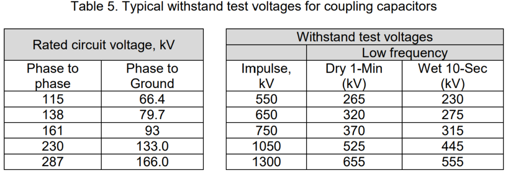
Coupling Capacitor Insulation Coordination
The voltage rating of coupling capacitors is crucial for protective relaying. The insulation of these capacitors must be capable of enduring the flashover voltage of the circuit where the capacitor is linked. Table 5 outlines the typical withstand test voltages for capacitors with various circuit-voltage ratings at altitudes below 3300 feet.
The flashover voltage at the capacitor’s location is influenced not only by the line insulation but also by the insulation of other equipment like circuit breakers, transformers, and lightning arresters. However, there might be scenarios when these devices are disconnected from the line, leaving the capacitor exposed without the protective benefits of other equipment. For example, a switch may be opened between a breaker and the capacitor, or a breaker may be opened between a transformer or an arrester and the capacitor. In such cases, the capacitor must withstand the voltage surging over the line at the point of connection.
In certain cases, transmission lines may have excessive insulation, either due to unusual insulator contamination or preparation for a future higher voltage. Regardless, the coupling capacitor must endure the actual line flashover voltage unless there are permanently connected devices that limit the voltage. At altitudes exceeding 3300 feet, the flashover value of air-insulated devices decreases. To address this, additional insulation may be necessary for the line and other terminal devices. In such cases, specifying the next higher standard voltage rating for the coupling capacitor is common, especially if the altitude is known to exceed 3300 feet.
If a coupling capacitor potential device is intended to operate at the next standard rated circuit voltage below its rating, it is crucial to inform the manufacturer. In this scenario, a special auxiliary capacitor will be provided to ensure the device receives the normal tap voltage, even if the applied voltage is one step less than rated. This ensures the device has a rated burden of 120 watts. Without the special auxiliary capacitor, the rated burden would be around 64% of 150 watts, rather than the desired 80%. This consideration also applies to bushing potential devices, although sometimes a nonstandard transformer unit may be required to achieve 80% of rated output when the device operates at the next standard rated circuit voltage below the bushing rating.
Voltage Transformer Output
The required output from a voltage transformer core is influenced by the specific application and the type of connected load. Devices like kWh or kArh meters operate under normal load conditions and demand high precision for voltages within the range of 80-120% of the nominal voltage. Accuracy classes for metering cores are categorized as 0.1 (laboratory), 0.2, 0.5, and 1.0.
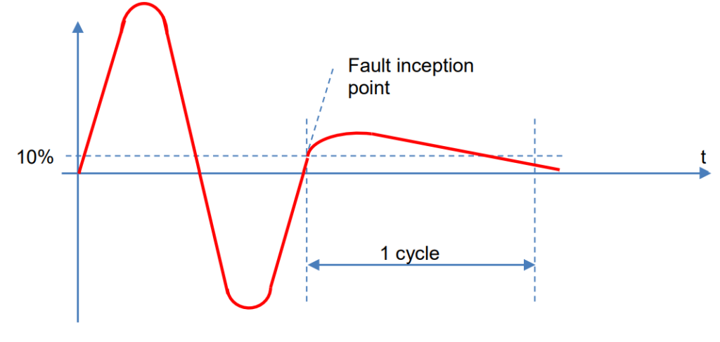
In the case of protection relays and disturbance recorders, data about a primary disturbance must be conveyed to the secondary side. For such windings, lower precision is acceptable, but there is a need for a high capability to transform voltages from “5-Vf x rated voltage” since protection relays must measure and disconnect the fault. Additionally, protection transformers require a good transient response, which can be challenging for Capacitive Voltage Transformers (CVTs). In CVTs, the energy stored in the capacitive voltage divider and in the Interposing Voltage Transformer (IVT) can result in a transient voltage oscillation on the secondary side.
This transient oscillation comprises a low-frequency component (2-15 Hz) and a high-frequency oscillation component (900-4000 Hz), as illustrated in Figure 7. The time constant for the high-frequency component is short (<10 ms), while the low-frequency component has long time constants. The magnitude of these oscillations is determined by the fault inception angle. Larger capacitances in the voltage divider lead to lower amplitudes of the low-frequency oscillation. According to IEC 186, the secondary value, one cycle after a solid short circuit, should be lower than 10%.
Voltage Transformer Ferro Resonance
Ferro-resonance is a phenomenon that can occur in circuits containing a capacitor and a reactor with an iron core, which acts as a non-linear inductance. Both Capacitive Voltage Transformers (CVTs) and magnetic Voltage Transformers (VTs) can experience ferro-resonance.
For a magnetic VT, ferro-resonance involves oscillation between the VT inductance and the network capacitance. This phenomenon can occur in ungrounded networks, and it is often triggered by a sudden change in the network voltage. Ferro-resonance can manifest with sub-harmonic frequencies as well as harmonic frequencies. Detecting the risk of ferro-resonance can be challenging, but as soon as a system with a voltage transformer is left ungrounded, precautionary measures should be taken. Capacitive charged systems with a VT also pose a risk that needs consideration.
To dampen ferro-resonance in a magnetic VT, a 27-60 Ω, 200 W resistor is typically connected across the open delta winding. The resistor’s value should generate a current as high as possible while remaining below the thermal rating of the voltage transformer.
CVTs, with their capacitor and Instrument Voltage Transformer (IVT), inherently form a ferro-resonance circuit. This process is triggered by a sudden voltage change, leading to sub-harmonic oscillations that must be damped to prevent transformer damage. The IEC standard mandates that CVTs must be equipped with ferro-resonance damping elements, usually comprising a saturating reactor and a resistor in each phase.
Secondary Circuit Fusing
Secondary fusing in voltage transformer installations is crucial for system safety. These fuses should be strategically placed at the initial box where the three phases converge. The circuit leading up to this point is designed to minimize the risks associated with faults.
In the three-phase box, individual fuses are incorporated to facilitate circuit protection for various loads, including protection and metering. The selection of these fuses is critical to ensuring prompt and dependable fault clearance. This consideration is particularly important for faults occurring at the end of the cabling. Additionally, the fuses must be designed to address ground faults and two-phase faults to comprehensively safeguard the system.
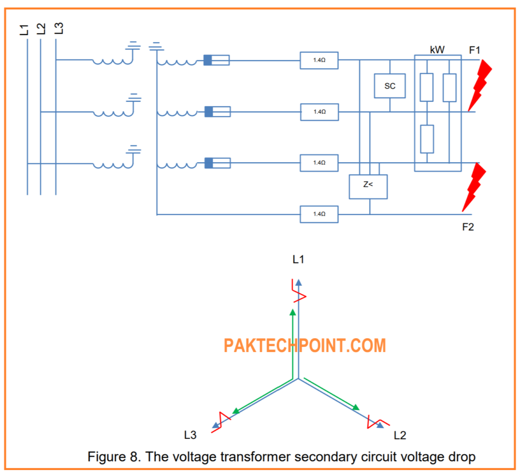
Secondary Cabling Voltage Drop
The accuracy of a voltage transformer is specified at its secondary terminal. To ensure the overall circuit accuracy aligns with this specification, it’s essential to assess the voltage drop and angle error in the secondary cabling. These factors must be kept within limits defined by the transformer class specification to maintain the accuracy of the entire circuit.
Figure 8 illustrates the voltage drop in the secondary circuit of a voltage transformer. This visual representation helps in understanding and analyzing the impact of secondary cabling on the overall accuracy of the voltage transformer system.
Voltage Transformer Overloading Effect
When the burden exceeds the rated value, errors in the voltage transformer system will increase, as indicated by the extrapolated data in Table 4. Beyond the risk of overheating, a significant concern is the associated rise in tap voltage. As the burden surpasses the rated value, the tap voltage tends to increase proportionally. The challenge with higher tap voltage is the adjustment of the protective gap, which must be set for a higher arc-over voltage.
The protective gap is designed to withstand four times the normal tap voltage for one minute, and it is adjusted to arc over at about twice the normal voltage. This adjustment considers that, for certain ground faults, the applied voltage may increase to approximately √3 times the normal voltage. Therefore, the protective gap should not arc over for any voltage that the protective-relaying equipment is intended to handle.
In situations where thermal overloading is not a concern, gap flashover may become problematic during intentional overloading of a capacitance potential device. Consulting the manufacturer before deliberately overloading the device is crucial. Short-circuiting the device’s secondary terminals, an extreme form of overloading, will continuously arc over the gap during the short circuit. While this may not damage the device, it could compromise the gap’s effectiveness in protecting the equipment.
It’s worth noting that standard rated burdens are specified as if a device were connected and loaded as a single-phase element. However, in reality, the secondary windings of three devices are interconnected and collectively loaded. Therefore, for accurate assessment under unbalanced voltage conditions, such as during short circuits, certain conversions must be performed to determine the effective burden on each device. This consideration is applicable to any type of voltage transformer.
Instrument Voltage Transformers (IVT) and Capacitance Voltage Transformer (CVT) Comparison
Capacitance voltage devices are chosen for protective relaying purposes when they offer significant cost advantages over voltage transformers. While these devices are more budget-friendly, they are not as precise as voltage transformers, and they may exhibit unwanted transient inaccuracies if not properly loaded. In situations where a voltage source is needed for protective relays, especially for circuits with voltages around 69 kV and higher, coupling-capacitor voltage devices become a more economical option compared to voltage transformers. Cost savings may also be realized below 69 kV, particularly when carrier current is involved, as the coupling capacitor of a voltage device can serve the dual purpose of connecting carrier-current equipment to the circuit at minimal extra expense.
Bushing voltage devices are even more budget-friendly, provided they have a sufficiently high rated burden capacity. However, the main capacitor of a bushing voltage device cannot be used to couple carrier-current equipment to a power circuit. Despite the cost advantages of capacitance voltage devices, when evaluated in terms of dollars per volt-ampere, voltage transformers emerge as a much more cost-effective option.
In scenarios where two or more transmission-line sections are connected to a common bus, a single set of voltage transformers connected to the bus typically has enough capacity to supply protective-relaying equipment for all the transmission lines. On the other hand, using a single set of capacitance voltage devices may fall short, and adding extra devices to meet capacity requirements could quickly negate the initial cost advantage. Therefore, even for a single circuit, the consideration of bus voltage transformers is recommended, especially when there’s a possibility of future requirements involving additional circuits.
Voltage transformers energized from a bus offer an advantage in protective-relaying systems that rely on “memory action” for reliable service. When a transmission line section protected by such relaying equipment is closed in on a nearby short circuit, having voltage transformers connected to the bus ensures that the protection relays receive voltage before the line breaker is closed. This allows for efficient memory action. On the other hand, if the voltage source is on the line side of the breaker, common with capacitance voltage devices, the relays may initially lack voltage, rendering memory action ineffective. This situation can lead to the relays not working properly if the voltage is too low, particularly in the presence of a metallic fault with no arcing. In such cases, backup protection relaying at other locations becomes necessary to clear the fault from the system.
Some individuals express concerns about using bus voltage transformers, fearing that issues with a single voltage transformer could impact the protective relaying for all lines connected to the bus. However, this objection is not overly severe, especially if line relays are configured not to trip on loss of voltage during normal load and if a voltage-failure alarm is installed.
In the case of ring buses, where there is no satisfactory location for a single set of bus voltage transformers to serve the protection relays of all circuits, capacitance voltage devices on the line side of the breakers for each circuit are considered a suitable solution, particularly if they are more cost-effective.
When step-down power transformers are present and voltage is needed for protective-relaying equipment, there is a consideration of obtaining the protection relay voltage from the low-voltage side of the power transformers to avoid the expense of a high-voltage source. However, this low-voltage source can only be utilized in specific situations.
Power Transformer Reliability:
When considering the reliability of the power source, the number of power transformers in operation plays a crucial role. In the scenario where there is only one power transformer, any downtime or removal of this transformer from service results in a loss of the power source. On the other hand, if multiple power transformers operate in parallel, each equipped with its breaker, the power source becomes more reliable, as the failure of one transformer doesn’t lead to a complete loss of power.
Polarizing Directional-Ground Protection Relays:
The availability of a suitable source for polarizing directional-ground protection relays is another important consideration. In power transformers configured in a wye-delta connection with the high-voltage side in wye and a grounded neutral, the neutral current can serve as a source for polarizing. However, if the high-voltage side lacks a grounded wye connection, a high-voltage source becomes necessary for directional-ground relays. This source may also be utilized for phase protection relays. Additionally, the presence of distance relays prompts an examination of the need for “transformer-drop compensation.”
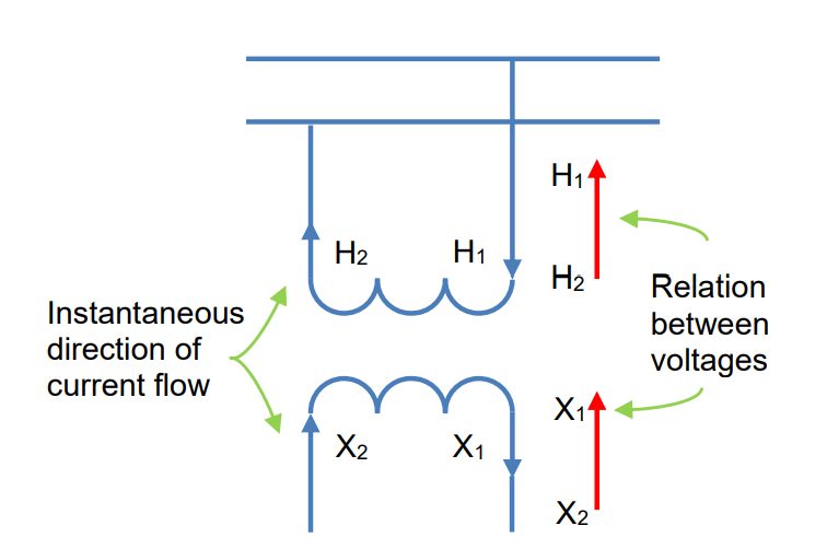
Voltage Transformer Terminals and Polarity:
The terminals of voltage transformers are distinctly marked to indicate the polarity of the primary and secondary windings. Typically, “H1” and “X1” are used for high-voltage and low-voltage terminals, respectively (with the addition of “Y1” for tertiary windings). In capacitance voltage devices, the labeling simplifies to “X1” and “Y1,” with “H1” being implicit in the equipment configuration. Polarity marks hold significant importance, much like in current transformers, signifying that when current enters “H1,” it exits “X1” (or “Y1”). This establishes a consistent relationship between high and low voltages, ensuring that “X1” (or “Y1”) maintains the same instantaneous polarity as “H1.”
Low-Tension Voltage for Distance Relays
To ensure that line-to-line voltages on the high-voltage side are accurately reproduced, the connection of voltage transformers must align with the configuration of the power transformer bank. The choice of connection is influenced by the power transformer connections, which are typically wye-delta or delta-wye, even though voltage transformers can be connected as needed.
Let’s first understand the standard method of connecting wye-delta or delta-wye power transformers. When specifying the connections of a power-transformer bank, the high-voltage connection is mentioned first. For instance, a wye-delta transformer bank has its high-voltage side connected in wye. This standard method, although directly applicable to power transformers, can also guide the connections of voltage transformers.
Power-transformer banks are often connected wye-delta or delta-wye, whereas voltage transformers need to be connected in a way that reproduces the line-to-line voltages on the high-voltage side. The specific connection method chosen will depend on the power-transformer connections. Whether the power-transformer bank is connected wye-wye or delta-delta, the voltage transformer connections would align with the high-voltage side. However, due to the prevalent wye-delta or delta-wye connections in power transformers, a technique is employed to achieve the desired connections for voltage transformers.
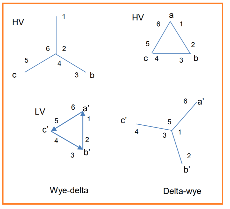
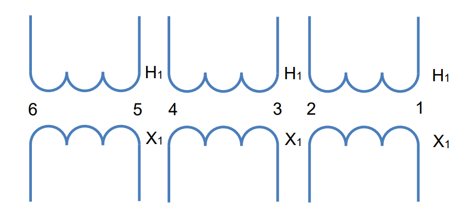
In a standard power transformer connection, when a balanced three-phase load is applied to the transformer bank, the current in each phase on the high-voltage side leads the corresponding current on the low-voltage side by 30°. Similarly, the no-load line-to-line voltages on the high-voltage side lead the corresponding low-voltage line-to-line voltages by 30°. This alignment is depicted in Figure 11, where a’, b’, and c’ correspond to a, b, and c, respectively.
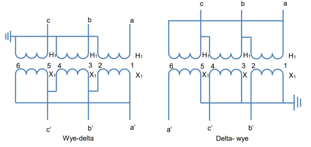
To achieve this alignment in practice, consider three single-phase transformers, each with primary and secondary windings designated as 1-2. Assuming these transformers are rated for either line-to-line or line-to-ground connection, connecting the numbered ends as indicated in Figure 11 results in the connections illustrated in Figure 13. This method ensures the desired alignment of currents and voltages in both the high-voltage and low-voltage sides of the transformers.
Let’s explore the voltage transformer connections on the low-voltage side, specifically used to supply voltage to distance protection relays. The configurations vary based on the connection of power transformers.
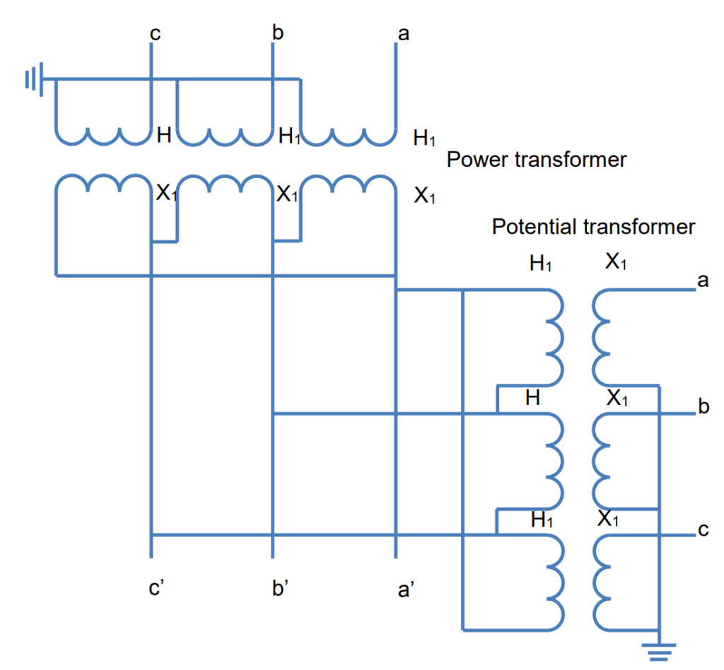
Figure 14 illustrates the connections when power transformers are wye-delta connected. In this arrangement, the line-to-line voltages on the secondary side of the voltage transformers will have the same phase-sequence components as those depicted in Figure 10.
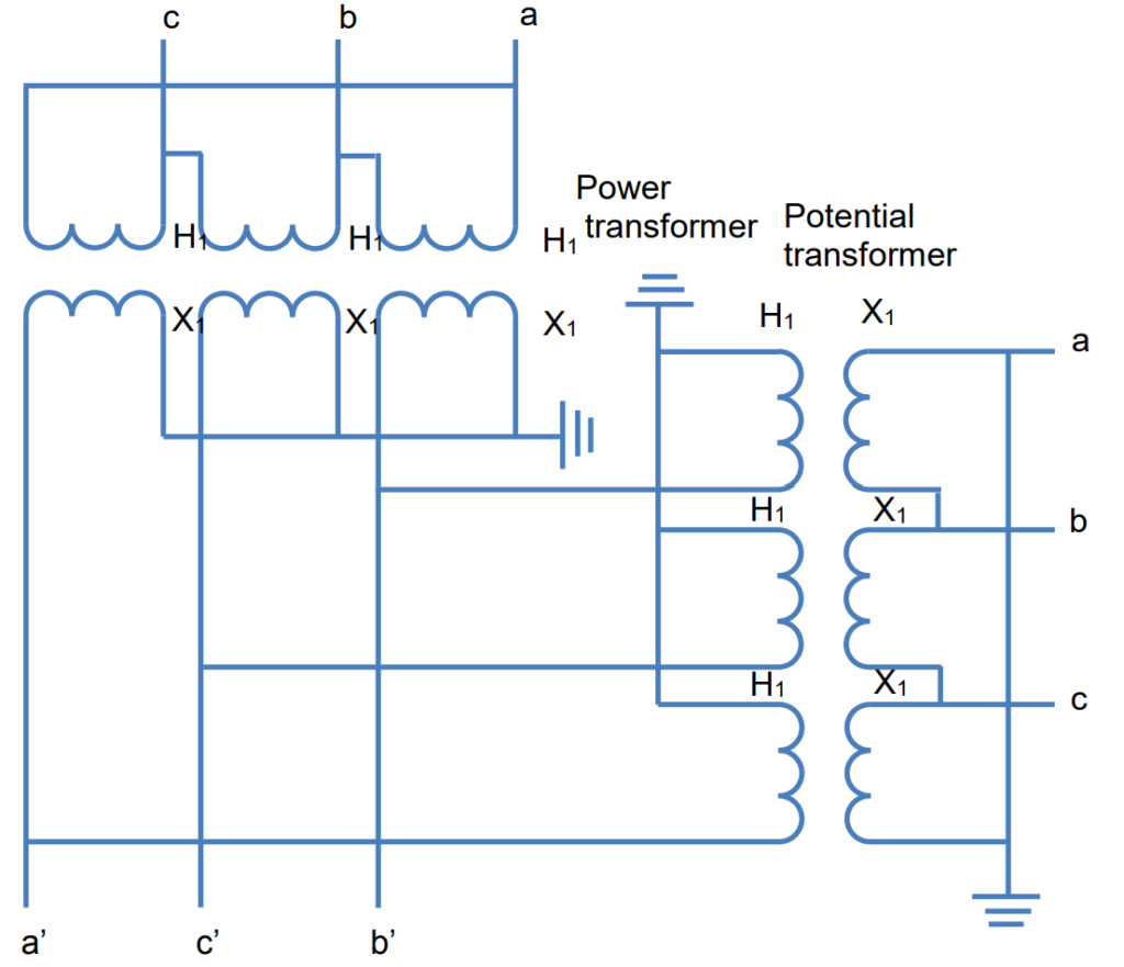
If power transformers are delta-wye connected, the connections are shown in Figure 15. Similar to the wye-delta configuration, the line-to-line voltages on the secondary side of the voltage transformers will exhibit the same phase-sequence components as illustrated in Figure 10. This assumption is made while neglecting any voltage drop or rise due to load or fault currents passing through the power transformers.
In certain situations, it might be necessary to have voltage transformers with delta-delta or wye-wye connections, or if the voltage magnitudes are not as required. To address these scenarios and obtain the necessary voltages for distance protection relays, auxiliary voltage transformers need to be introduced.
These auxiliary transformers play a crucial role in achieving the desired voltage configurations, ensuring compatibility with the requirements of distance protection relays. The guidance provided for establishing connections in distance protection relays can serve as a valuable reference for configuring other connections needed for phase relays and other protective elements within the system.
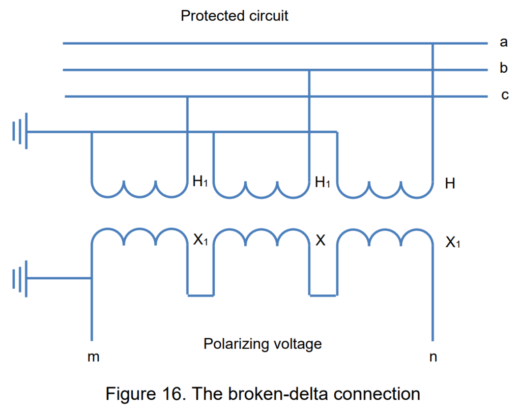
Connections for Obtaining Polarizing Voltage for Directional-Ground Relays
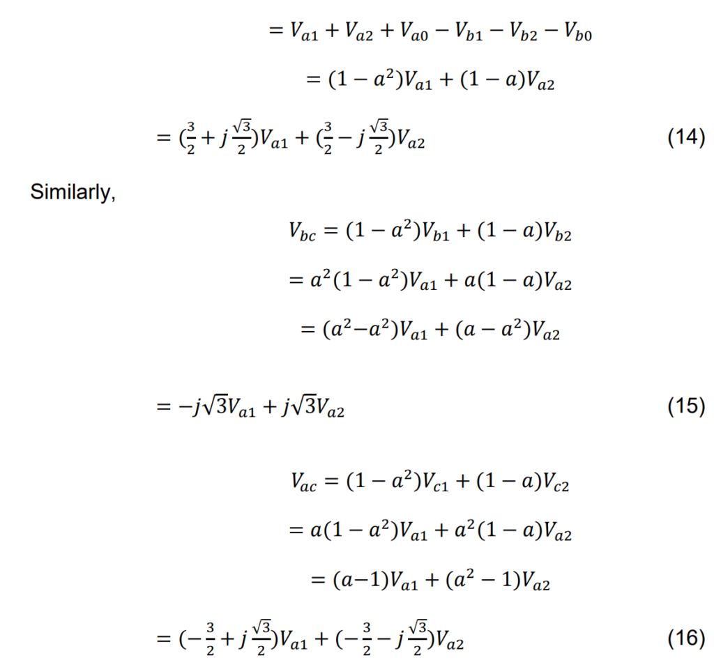
To obtain the necessary polarizing voltage for directional-ground relays, a specific configuration known as the “broken-delta” connection is employed. The outlined connections for achieving this setup are illustrated in Figure 16. The voltage across the terminals in this broken-delta connection can be expressed as follows:
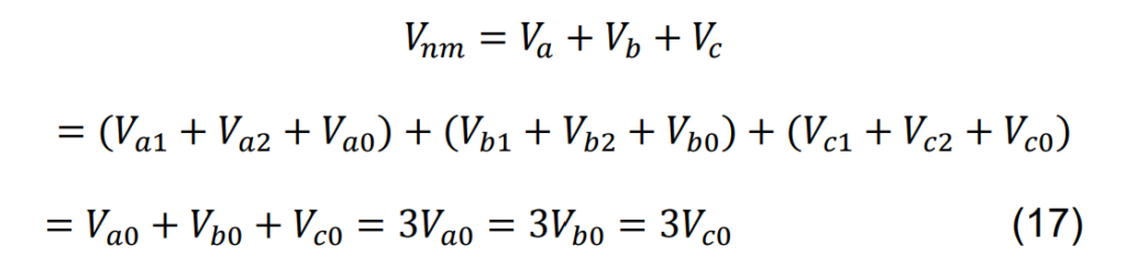
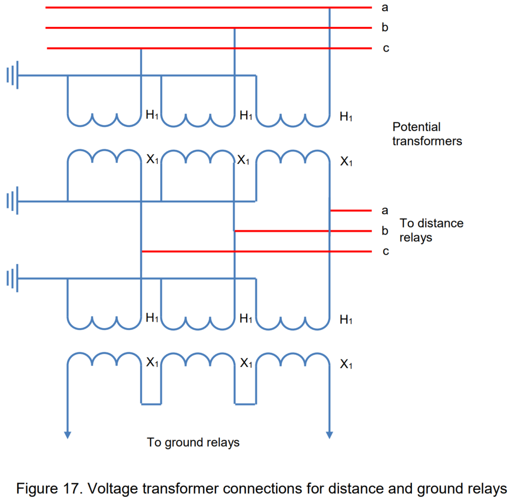
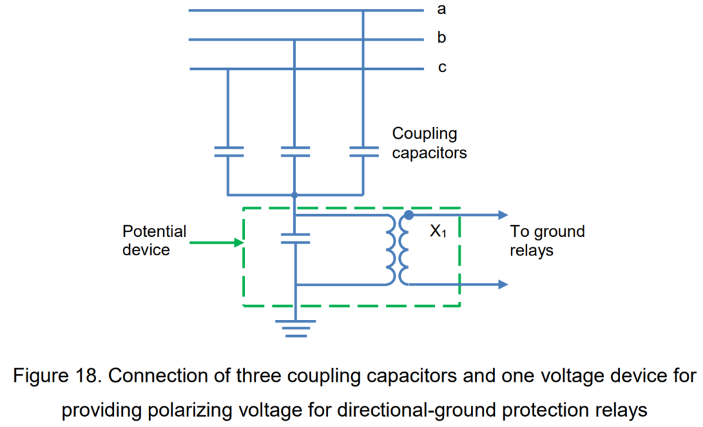
Simply put, the polarizing voltage required for directional-ground relays is three times the zero-phase-sequence component of any phase’s voltage. The specific connections to establish this configuration will be contingent on the type of voltage transformer involved and the secondary voltage requirements for relays other than ground relays. For instances where voltage is needed for distance relays, the connections depicted in Figure 17 should be implemented. However, if voltage is exclusively required for polarizing directional-ground relays, a setup involving three coupling capacitors and one voltage device, as outlined in Figure 18, would be adequate. The voltage derived from this connection is precisely 3 times the zero-phase-sequence component.
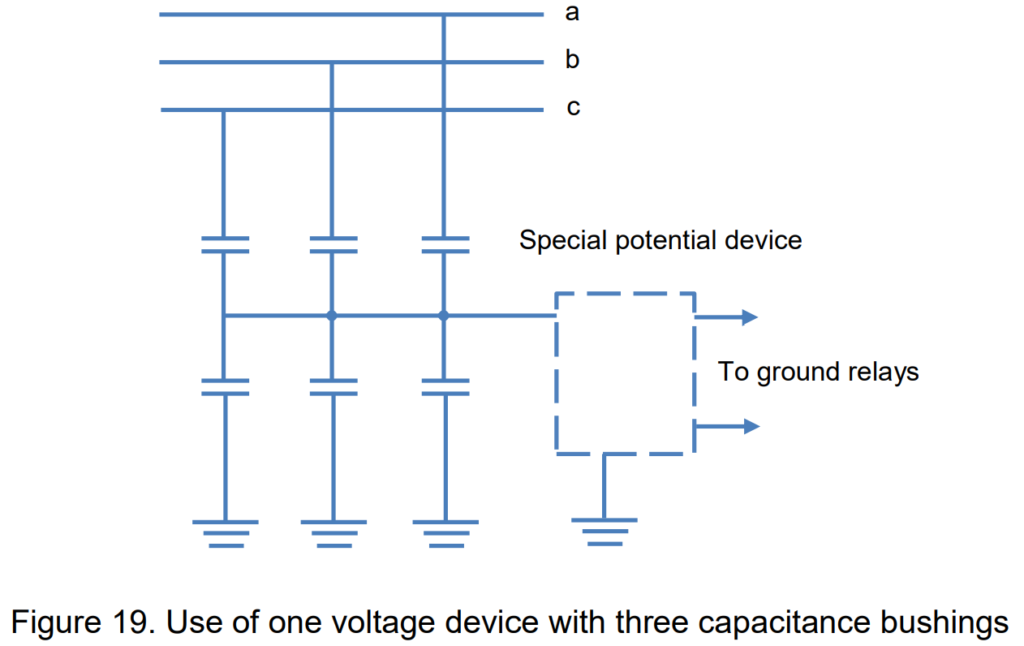
The arrangement illustrated in Figure 18 may not be universally applicable when working with bushing voltage devices. This is due to the fact that certain portions of the capacitance associated with the auxiliary capacitor may be inherent to the bushing and inseparable from it. Additionally, the capacitance to the ground in the interconnecting cable might have a notable influence on the configuration.
To address this limitation, the three capacitance taps can be interconnected, and a dedicated voltage device can be linked across the tap voltage, as depicted in Figure 19. However, it’s important to note that the rated burden in this configuration may be lower than the values outlined in Table 2.