The topic, we are going to discuss have many names generally use like voltage tester, electrical tester, neon lamp tester, neon line tester and contact voltage tester etc. But don’t confuse this topic with proximity tester or non contact voltage tester.
An electric tester is a tool used to detect voltage in wires or outlets by sensing a small amount of capacitively coupled current from the live circuit to the tester and back to ground. It typically features a neon lamp that lights up when it receives sufficient voltage, usually around 80 volts. However, electric testers are not suitable for testing DC current because they rely on components like capacitors that are designed for AC circuits, which have changing polarity and direction. DC current, with its constant polarity, does not trigger the tester.
Why Electric Tester Does Not Work on DC?
To test a DC circuit accurately, a different device, such as a multimeter, is needed. A multimeter can measure the actual voltage level in DC circuits and offers versatility in measuring other electrical properties like resistance and current. It’s essential to exercise caution when using a multimeter on live circuits, as incorrect settings or probes can lead to short circuits or device damage. Always follow the provided instructions and safety warnings when using a multimeter.
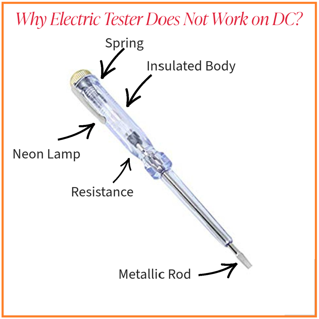
Diagram of Electric Tester:
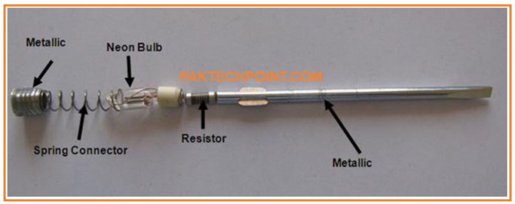
Construction of Neon Lamp Tester:
A Neon Line Tester is a simple tool used to identify the live or Phase Wire in an electrical system. It consists of six main components:
Metallic Rod:
- A cylindrical rod, partially designed as a flat screwdriver.
- Mainly resides inside the insulated body.
- Allows line current to flow towards the resistance.
Resistance:
- Connected between the metallic rod and the neon lamp.
- Reduces current flow, making the tester safe to use.
- Value is higher than 1.5MΩ.
Neon Lamp:
- Small glass capsule containing neon and other gases at low pressure.
- Has two electrodes and connects to the resistance and the spring.
- Lights up when live wire is detected.
Spring:
- Connects the neon lamp to the metallic touch screw.
Metallic Touch Screw:
- Secures all components inside the insulated body.
Insulated Transparent Body:
- Made of hard plastic.
- Protects users from electric shock and allows visibility of the neon lamp.
In simple terms, when the metallic rod of the tester touches a live wire, the current flows through the resistance to the neon lamp, causing it to light up, indicating the presence of a live wire, while the insulated body keeps the user safe from electric shock.
Do You Know Basic Principle of Voltage Measurement?
Current is generated in a circuit when there is a potential difference, also known as voltage, between two points in it and this causes electric charge (current) to flow along its path through it.
India, like many countries worldwide, maintains a standard voltage or potential difference between Phase (Live) wire and Neutral wire of around 220 volts – typically available through home outlets and used to power most household appliances.
Under normal conditions, Neutral wire voltage should be comparable to Earth (Ground). Therefore, under ideal circumstances the potential difference between Neutral and Earth should be zero or very close; however due to system imbalances or leakages there could be up to 5V between Neutral and Earth which would need to be addressed by additional measures in order for proper functioning.
Neon Lamp Tester Working principle:
A Neon Lamp Tester lights up to indicate the presence of a live wire, using a very simple yet effective mechanism. When the metallic rod of the tester touches a live wire and the user touches the metallic touch screw at the end, a circuit is completed, allowing current to flow through the metallic rod.
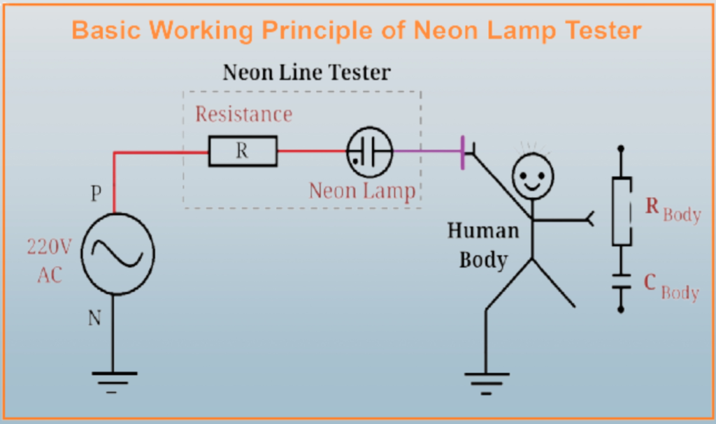
This current then passes through a high resistance inside the tester, which significantly reduces the current before it reaches the neon lamp. The small amount of current that does reach the neon lamp is enough to make it glow, signaling the presence of a live wire.
Meanwhile, this reduced current travels through the user’s body to the ground, completing the circuit. The current is minimal due to the high resistance in the tester, ensuring the user’s safety. The user’s body acts as a conductor, allowing the small current to pass through, with the body’s inherent resistance and capacitance also influencing the current flow.
The neon line tester safely indicates the presence of a live wire by allowing a minimal, non-harmful current to flow through the user’s body to the ground, causing the neon lamp in the tester to glow.
Why Electric Tester Does Not Work on DC?
The operation of a neon line tester relies on the completion of an electrical circuit, which usually involves the current flowing through the tester, the user’s body, and eventually to the ground when dealing with AC supply. In an AC system, the ground or earth is often at a different potential than the live wire, allowing current to flow and complete the circuit, causing the neon lamp to glow.
However, in a DC supply system, the terminals are usually not referenced to ground, meaning there is no potential difference between the user (or ground) and the negative/positive terminal of the DC supply when touched separately. Consequently, a current path is not established, and the neon lamp does not glow as the circuit is not complete.
Additionally, neon lamps have a characteristic called “striking voltage,” which is the minimum voltage required to ionize the gas inside the lamp and make it glow. In many DC scenarios, even if the lamp were connected in a way that could allow it to complete a circuit, the available voltage might not be sufficient to meet or exceed this striking voltage, especially after the high resistance in series with the lamp.
Here’s why an electric tester may not work on DC current:
Design of Voltage Tester:
- Voltage testers are often designed to detect the presence of AC voltage. They typically contain components like a neon bulb or LED and a resistor. These components rely on the alternating nature of AC voltage to operate.
Alternating Current (AC):
- In AC circuits, the voltage continuously alternates in polarity, meaning it changes direction periodically (typically 50 or 60 times per second, depending on the region). This continuous change in polarity causes the components in the voltage tester to blink or light up, indicating the presence of voltage.
Direct Current (DC):
- In DC circuits, the voltage flows continuously in one direction without changing polarity. Since DC does not have the alternating characteristics of AC, the components in a typical voltage tester, such as the neon bulb or LED, do not have the necessary alternating voltage to operate. As a result, they may not light up or provide accurate readings on a DC circuit.
To work with DC circuits, you would typically need a different type of tester designed specifically for DC voltage. These testers often use different principles or components, such as a digital multimeter, which can accurately measure both AC and DC voltage, or a dedicated DC voltage tester with appropriate indicators.
The design of most standard voltage testers is tailored to AC circuits, and they may not operate correctly or at all when testing DC circuits because they rely on the alternating nature of AC voltage to function. To work with DC circuits, it’s advisable to use specialized testers designed for DC voltage measurement.
Certainly, let’s explain deeply into how an electric tester works and why it doesn’t function on DC (Direct Current) circuits, as well as the role of multimeters in testing DC circuits:
Using a Voltage Tester to Measure Electrical Current Flow
Voltage testers are essential tools used to accurately gauge electrical current flow within an electric circuit, from measuring its flow from wires, verifying proper grounding practices, and assessing whether there’s adequate voltage available on its circuits.
A voltage tester is straightforward. Its main component consists of a small neon bulb, resistor, spring enclosed within a protective casing. Two insulated wires connected to its bottom provide access to two metal test probes for testing voltage levels.
This tester should only be used when current is active; its main use is for verifying presence of current and proper grounding in a circuit.
Testing Procedure:
To utilize the tester, one probe should be applied to one wire or connection, with another probe touching another wire or connection that could potentially receive electricity. When this occurs, an indicator light in the housing of the tester will illuminate to indicate its presence – and indicate any electrical current passing through it.
To conduct initial tests on an outlet that may be defective, one probe of a tester should be placed into one slot in the outlet while the second probe should be inserted into another. If both slots are functioning as intended, the light on the tester should illuminate.
For further investigation of any non-functioning outlet, its outlet should be pulled away from the wall and probes placed on each terminal screw connection. If a bulb lights up after this process is performed, this indicates that power is flowing to but not through it; suggesting there may be some sort of fault within it.
Finding the Issue:
If the test bulb remains non-luminous, this indicates a lack of current flowing through an outlet. This could be caused by anything from a blown fuse to a tripped circuit breaker to disconnected or broken wires behind an outlet.
Selecting a Voltage Tester:
When purchasing a voltage tester, it is recommended that it can handle up to 500V for increased safety and accuracy in various applications.
A voltage tester is a fundamental tool used to measure the flow of electrical current within a circuit. It’s an integral instrument in detecting whether current is flowing through a wire, verifying proper grounding, and assessing whether a wire has adequate voltage.
How an Electric Tester Works on AC Current:
- An electric tester, such as a voltage tester or neon tester, detects the presence of voltage in a wire or outlet by relying on the principles of capacitance and the behavior of AC current.
- When you place the tester near a live AC wire, a small amount of current capacitively couples from the live wire to the tester and then back to ground.
- The tester contains a neon lamp that is designed to glow when it receives a sufficient voltage, typically around 80 volts for many models.
- The key to the tester’s operation is the continuous change in polarity and direction of AC current. As the AC voltage alternates, the tester’s neon lamp flickers or lights up, indicating the presence of voltage.
Using a Multimeter for DC Circuits:
- To test a DC circuit, you need a different device, such as a multimeter, which is capable of measuring DC voltage accurately.
- A multimeter can measure the actual voltage level on the wire, making it suitable for both AC and DC circuits.
- Multimeters are versatile tools that can also measure other electrical properties like resistance and current.
- When using a multimeter on a live circuit, it’s crucial to exercise caution and follow safety procedures to avoid short circuits or damage to the device. Always read and adhere to the instructions and safety warnings provided with your multimeter.