This article is about To guide the responsible persons in conducting GIS 13.8kV Switchgear Circuit Breaker test procedure.
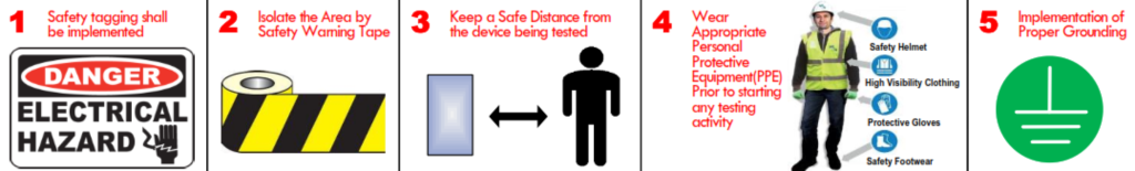
SAFETY PRECAUTIONS – The following Safety precautions shall be taken in consideration prior, during and after conducting the test measurements.
- Safety tagging shall be implemented.
- Isolate the Area by Safety Warning Tape.
- Keep a Safe Distance from the device being tested.
- Wear Appropriate Personal Protective Equipment(PPE) Prior to starting any testing activity.
- Implementation of Proper Grounding.
13.8kV Switchgear Circuit Breaker Test Procedure
TEST EQUIPMENTS: Megger IR test Kit, Contact Resistance Test Kit, Circuit Breaker Analyzer
- Perform the Insulation Resistance test.
- 1.1 Inject 5kV DC for 1 minute at Phase R with Phase Y + B connected to earth as per the following Test connection diagram:
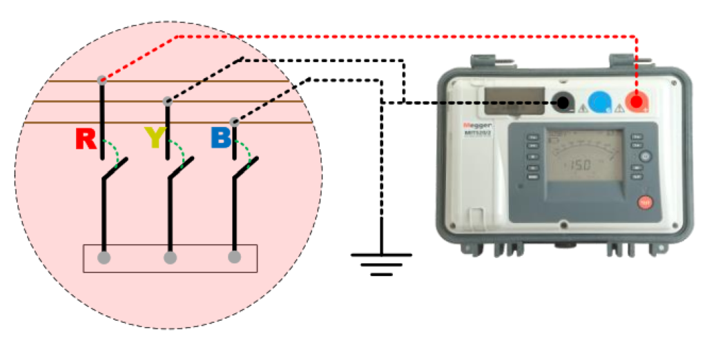
1.2 Repeat Above steps for Phase Y and B
1.3 Record the measured values in the applicable test forms and evaluate as per acceptable standards/criteria (>100 MΩ).
- Perform the Contact Resistance test.
2.1 Inject 100A for 1 minute at Phase R as per the following Test connection diagram:
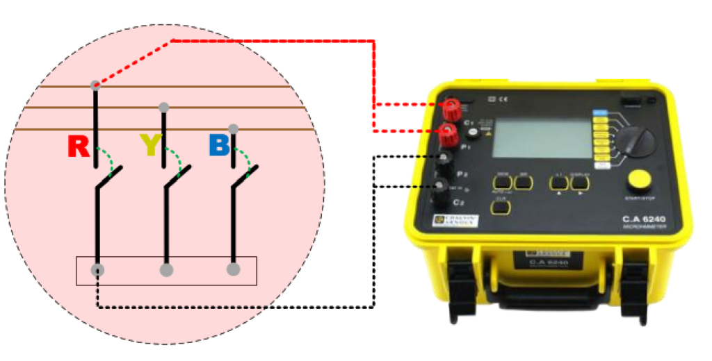
2.3 Repeat Above for Phase Y and B
2.3 Record the measured values in the applicable test forms and evaluate as per acceptable standards/criteria (>1 GΩ).
- Perform the OPEN and CLOSE Timing test as per the following Test connection diagram.
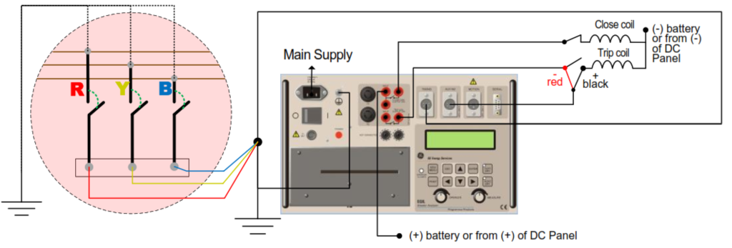
3.1 Print and Record the measured values in the applicable test forms and evaluate as per acceptable standards/criteria (< 20 msec).
Circuit Breaker Anti-Pump Relay Function verification test.
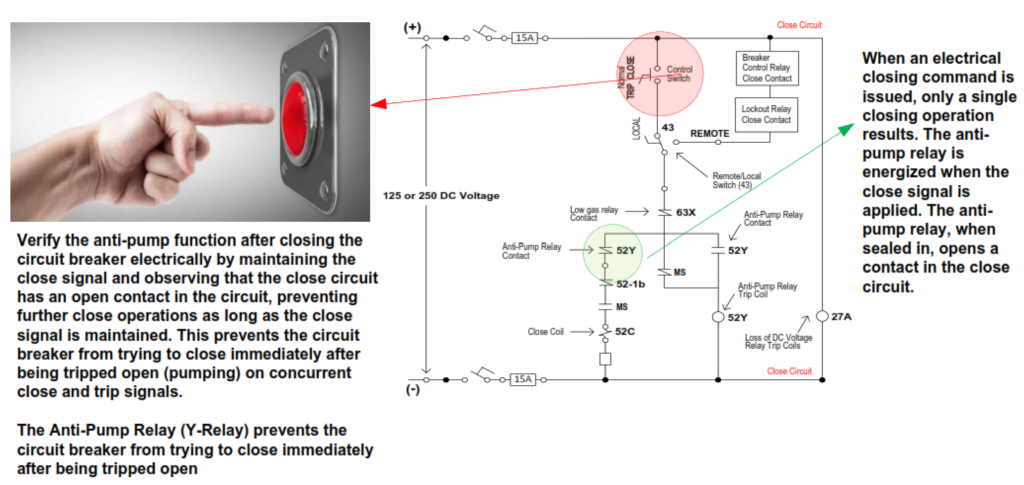
When an electrical
closing command is
issued, only a single
closing operation
LOCAL
results. The antipump
relay
is
energized
when
the close signal is applied. The anti-pump relay, when
sealed in, opens a
contact in the close
circuit.
Verify the anti-pump function after closing the
circuit breaker electrically by maintaining the
close signal and observing that the close circuit
has an open contact in the circuit, preventing
further close operations as long as the close
signal is maintained. This prevents the circuit
breaker from trying to close immediately after
being tripped open (pumping) on concurrent
close and trip signals.
The Anti-Pump Relay (Y-Relay) prevents the
circuit breaker from trying to close immediately
after being tripped open.
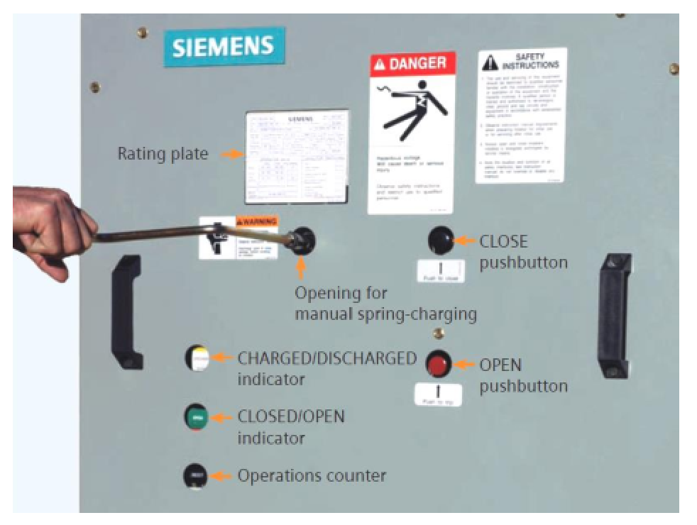
Verification of Circuit Breaker Indications during Racking in and out operation.
What is 13.8kV Switchgear?
At its core, a 13.8kV switchgear is designed to control the flow of electrical energy, providing the capability to isolate, protect, and switch various electrical circuits. The 13.8kV voltage rating indicates that this switchgear is suitable for medium voltage applications, striking a balance between higher voltages used in transmission systems and lower voltages found in end-user applications.
One of the primary functions of 13.8kV switchgear is to facilitate the distribution of electrical power from the primary source to various loads or distribution points. It typically includes circuit breakers, switches, fuses, and protective relays, all integrated into a cohesive unit. The combination of these components allows for the safe and efficient management of electrical currents.
The switchgear operates by enabling or interrupting the electrical current flow, providing a mechanism to isolate sections of the network during maintenance or in the event of a fault. This capability enhances the reliability and safety of the overall power distribution system. The 13.8kV switchgear is designed to handle the demands of medium voltage applications, ensuring optimal performance and longevity.
In addition to its operational functionalities, safety is a paramount consideration in the design of 13.8kV switchgear. These systems incorporate safety features such as interlocks, insulation, and protective enclosures to safeguard personnel and equipment from electrical hazards.
The installation of 13.8kV switchgear is strategic, often positioned at key points in the distribution network to ensure efficient power flow. These switchgear units are compatible with various protection and control schemes, contributing to the overall reliability and resilience of the power distribution infrastructure.
As technology advances, modern 13.8kV switchgear may incorporate smart features and digital monitoring capabilities, enabling remote operation, real-time diagnostics, and predictive maintenance. These advancements enhance the efficiency and responsiveness of power distribution systems, aligning with the evolving needs of today’s electrical grids.
In summary, the 13.8kV switchgear serves as a vital component in medium voltage power distribution, offering a combination of control, protection, and safety features. Its role in efficiently managing electrical energy contributes to the overall reliability and performance of power distribution systems across various industrial and commercial settings.