This article is about To guide the responsible persons like electrical, electronics and instrumentation engineers, supervisors and technicians in conducting GIS Circuit Breaker Pole Discrepancy Tests, HV and Partial Discharge Test on GIS Switchgear.
SAFETY PRECAUTIONS – The following Safety precautions shall be taken in consideration prior, during and after conducting the test measurements.
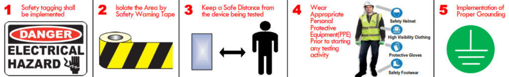
- Safety tagging shall be implemented.
- Isolate the Area by Safety Warning Tape.
- Keep a Safe Distance from the device being tested.
- Wear Appropriate Personal Protective Equipment(PPE) Prior to starting any testing activity.
- Implementation of Proper Grounding.
GIS Circuit Breaker Pole Discrepancy Test Procedure:
TEST EQUIPMENTS: Timer
The following activities must be completed before starting in pole discrepancy panel scheme and function check:
Ø Circuit breakers testing.
Ø LCC scheme & function check.
Ø Bus bar protection scheme & function check.
Ø Circuit breaker fail protection scheme & function check.
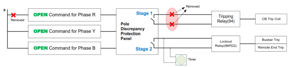
POLE DISCREPANCY STAGE 1 – Remove tripping signals for stage 2.
2.1 CLOSE Command Check:
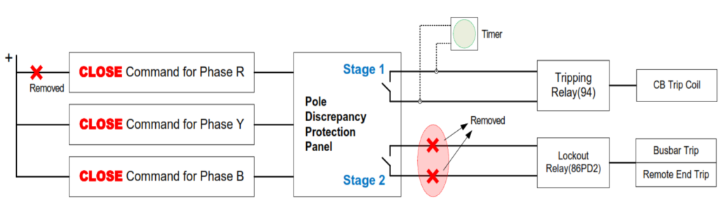
2.1.1 Open CB.
2.1.2 Remove Close Command for Phase R.
2.1.3 Close CB and check if CB tripped by Pole Discrepancy stage 1.
2.1.4 Record the time of stage 1.
2.1.5 Check alarms, indications and SAS
2.1.6 Normalize and Open CB
2.1.7 Repeat Steps above for Phases Y and B.
2.2 OPEN Command Check:
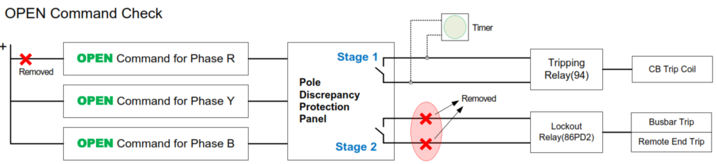
2.2.1 Close CB.
2.2.2 Remove Open Command for Phase R.
2.2.3 Open CB.
2.2.4 Check if CB re-tripped by Pole Discrepancy stage 1.
2.2.5 Record the time of stage 1.
2.2.6 Check alarms, indications and SAS.
2.2.7 Normalize and close CB.
2.2.8 Repeat Steps above for Phases Y and B.
POLE DISCREPANCY STAGE 2 – Remove tripping signals for stage 1
3.1 CLOSE Command Check
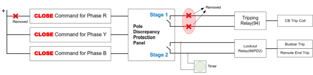
3.1.1 Open CB.
3.1.2 Remove Close Command for Phase R.
3.1.3 Close CB and check if CB tripped by Pole Discrepancy stage 2.
3.1.4 Record the time of stage 1
3.1.5 Check alarms, indications and SAS
3.1.6 Normalize and Open CB
3.1.7 Repeat Steps above for Phases Y and B.
3.2 OPEN Command Check
3.2.1 Close CB.
3.2.2 Remove Open Command for Phase R.
3.2.3 Open CB.
3.2.4 Check if CB re-tripped by Pole Discrepancy stage 2.
3.2.5 Record the time of stage 1.
3.2.6 Check alarms, indications and SAS.
3.2.7 Normalize and close CB.
3.2.8 Repeat Steps above for Phases Y and B.
What is Pole Discrepancy Test of GIS Circuit Breaker?
Here’s an overview of the GIS Circuit Breaker Pole Discrepancy Test:
The test aims to identify any discrepancies or imbalances in the operation of the individual poles of a GIS circuit breaker. A circuit breaker typically consists of multiple poles, each responsible for interrupting the current flow during a fault or overload condition.
The test involves a comprehensive examination of each pole’s response and timing during circuit breaker operations. This includes the opening and closing of the circuit breaker under various conditions.
The primary focus is on ensuring that all poles operate in synchronization. This means that when the circuit breaker is commanded to open or close, all poles should respond simultaneously. Any deviation in the timing or sequence of pole operations could indicate a potential issue.
The test may involve measuring the time delays associated with each pole. This includes the time taken for a pole to initiate and complete the opening or closing operation. Consistent and synchronized time delays are crucial for the proper functioning of the GIS circuit breaker.
Simulating fault conditions may be part of the test to evaluate how each pole responds to abnormal situations. This ensures that the GIS circuit breaker can effectively and uniformly interrupt the current flow during faults.
The test may include verification of sensors and actuators associated with each pole. This ensures that the monitoring and control elements of the GIS circuit breaker are functioning correctly.
Throughout the test, data related to the performance of each pole is recorded. Subsequent analysis of this data helps identify any discrepancies or anomalies. This information is valuable for predictive maintenance and troubleshooting.
Safety protocols are adhered to during the testing process to protect personnel and equipment. This may include implementing lockout-tagout procedures and using appropriate personal protective equipment.
The GIS Circuit Breaker Pole Discrepancy Test is a crucial step in ensuring the reliability and effectiveness of GIS technology in high-voltage applications. Detecting and addressing any issues with pole synchronization helps maintain the integrity of the electrical distribution system and prevents potential failures during critical operations.