EHV/HV tests on GIS (Gas Insulated Switchgear) and Partial Discharge (PD) tests on EHV GIS Switchgear are essential procedures conducted to assess the performance, reliability, and insulation integrity of the switchgear in high voltage environments.
Test Equipment: Portable UHF PD monitor; External UHF PD sensor; Coaxial cable; Noise sensor or band rejection filter; External UHF PD pulse generator(Doble LDC-7/UHF Pulse generator).
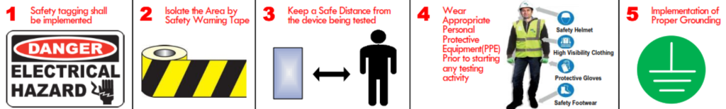
SAFETY PRECAUTIONS – The following Safety precautions shall be taken in consideration prior, during and after conducting the test measurements.
- Safety tagging shall be implemented.
- Isolate the Area by Safety Warning Tape.
- Keep a Safe Distance from the device being tested.
- Wear Appropriate Personal Protective Equipment(PPE) Prior to starting any testing activity.
- Implementation of Proper Grounding.
GIS Switchgear and Partial Discharge Test Procedure
Prior to performing the GIS EHV/HV Test, calibration of the GIS PD internal sensor shall first be conducted as per the following Steps:
1.1 Calibration of the GIS PD internal sensor without monitoring system.
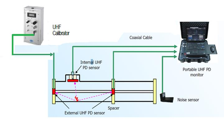
1.1.1 By Use of Internal/External Sensor
Ø 1-Connect UHF Calibrator to external UHF sensor and portable UHF PD monitor to internal UHF
sensor, Spacer and noise sensor as fig 1.1.1. Ø Record the spectrum reading from portable UHF
PD monitor.
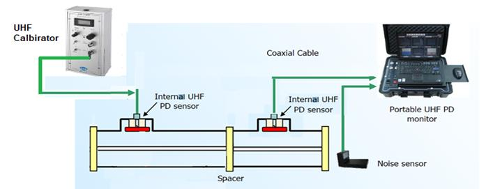
1.1.2 By Use of 3phase unified GIS using internal sensor
Ø Connect UHF Calibrator to internal UHF sensor and portable UHF PD monitor to another internal UHF sensor, Spacer and noise sensor as fig 1.1.2. Ø 2-Record the spectrum reading from portable
UHF PD monitor.
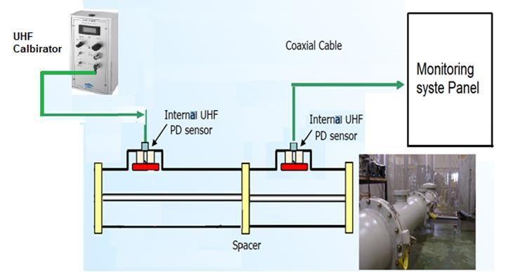
1.2 Calibration of the GIS PD internal sensor with monitoring system.
1.2.1 Connect UHF Calibrator to internal UHF sensor and portable UHF PD monitor to another internal UHF sensor, Spacer and noise sensor as fig 1.2.1
1.2.2 Record the spectrum reading from monitoring system panel.
Perform the GIS EHV/HV Test and GIS EHV Partial Discharge Test:
2.1 Connect all Circuit Breakers, disconnector switch, earth switch, and remove all earthing wires with CT shorted and VT connected to check the reading of voltage during test.
2.2 Connect EHV/HV tester to GIS as per fig. 2.3
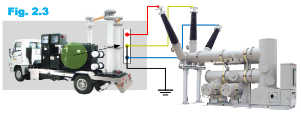
2.3 Connect VT during injection EHV/HV.
2.4 Inject voltage at phase R with Y+B connected to Earth as per the following:
2.4.1 Rated voltage for 3 mins
2.4.2 Increase the voltage gradually up to 1.2 rated voltage for 1 min.
2.4.3 Record the leakage current for GIS EHV/HV Test
2.4.4 Decrease the voltage gradually up to rated voltage to perform the GIS EHV partial discharge test as per fig. 2.4.
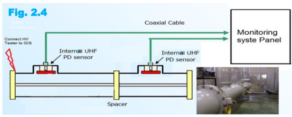
2.5 Print the the spectrum reading from portable UHF PD monitor or from mounting system panel if available.
2.6 EHV/HV Test Value shall be as indicated in the tables.
2.7 All the test results should be recorded in the test format and check list;
2.8 Repeat above for phase Y and B.