In Non-Standalone (NSA) networking, a User Equipment (UE) must connect to both LTE and 5G NR networks to utilize the combined radio resources for enhanced data transmission. The initial access procedures begin with the UE searching for and selecting an LTE cell. The UE scans the available frequency bands to find LTE cells and achieves downlink synchronization with the best available LTE cell based on signal quality. Once synchronized, the UE camps on this cell, establishing a connection that serves as the foundation for further interactions with the network.

Following cell selection, the UE initiates a Random Access (RA) procedure with the LTE cell. This procedure is essential for establishing a radio link between the UE and the network, enabling the UE to achieve uplink synchronization and request uplink resources. Once the RA procedure is complete, the UE and the LTE base station (eNodeB) proceed to set up a Radio Resource Control (RRC) connection. This connection allows for the exchange of signaling messages, facilitating the management of the UE’s connection and the initiation of data services.
The next step involves the initial context setup, where the eNodeB gathers necessary information about the UE. This context is crucial for making decisions regarding event handling and resource allocation, ensuring that the UE’s connection is maintained and optimized as it interacts with the network. Once the context is established, the network proceeds to set up an E-UTRAN Radio Access Bearer (E-RAB), a logical channel that carries user data such as voice, video, and multimedia services between the UE and the core network (Evolved Packet Core, EPC).
As the UE remains connected to the LTE cell, the eNodeB instructs it to measure the signal quality of neighboring 5G NR cells. This step, known as NR B1 measurement, helps identify the best NR cell for potential dual connectivity. Based on the measurement results, the eNodeB adds the corresponding gNodeB (NR base station) as a secondary gNodeB (SgNB) to the UE’s connection. This addition enables the UE to access NR cells, allowing it to benefit from the advanced capabilities of the 5G network.
Finally, the UE initiates another Random Access procedure, this time with the NR cell. This procedure establishes a radio link between the UE and the NR cell, achieving uplink synchronization and securing the necessary uplink resources for data transmission. By completing these steps, the UE successfully connects to both LTE and 5G NR networks, leveraging dual connectivity to enhance overall performance, increase data throughput, and improve user experience in NSA networking.
Cell Search and Selection
In the LTE network, the process of cell search and selection is crucial for establishing a connection between the User Equipment (UE) and the network. This procedure begins when the UE is powered on and starts searching for frequencies based on predefined channel rasters. In LTE, the channel raster granularity is set at 100 kHz, with the Primary Synchronization Signal (PSS) and Secondary Synchronization Signal (SSS) always located at the center of a cell’s carrier frequency. Once the UE detects the PSS or SSS, it identifies the carrier frequency and proceeds with further synchronization tasks.
The first step in this process is the acquisition of the Physical Cell Identifier (PCI). The UE detects the PSS on the frequencies identified by the Absolute Radio Frequency Channel Number (ARFCN) in a blind search manner, followed by the detection of the SSS. The PSS and SSS signals are essential for the UE to achieve downlink synchronization with the network. After detecting these signals, the UE can determine the PCI of the cell. The LTE system is designed with three distinct PSS sequences, each associated with 168 SSS sequences. By detecting the PSS and SSS sequences and determining their respective IDs, the UE can calculate the PCI using a predefined formula, allowing it to identify the cell it is attempting to connect with.
Once the PCI is acquired, the UE proceeds to obtain the Master Information Block (MIB), which is transmitted on the Physical Broadcast Channel (PBCH). The MIB contains essential information for the initial access process, particularly guiding the UE on how to retrieve System Information Block 1 (SIB1).

| IE | Description |
|---|---|
| dl-Bandwidth | Current downlink bandwidth. The downlink bandwidth affects the decoding of the physical downlink shared channel (PDSCH). |
| phich-Config | Physical HARQ indicator channel (PHICH) configuration parameter, including the information for calculating the PHICH position. The PHICH position affects the decoding of the physical downlink control channel (PDCCH) and PDSCH. |
| systemFrameNumber | System frame number (SFN), which is used for synchronization between the UE and the network.This IE indicates the eight most significant bits (MSBs) of the 10-bit SFN. The two least significant bits (LSBs) of the SFN are carried in the PBCH transport block as part of channel coding. |
| schedulingInfoSIB1-BR | Scheduling information of SIB1. |
| systemInfoUnchanged-BR | The value TRUE indicates that no change has occurred in SIB1 at least over the system information (SI) validity time. |
SIB1 is critical as it contains information related to cell access, selection, and scheduling information for other SIB messages. Without decoding SIB1, the UE cannot access other necessary system information.
Following the acquisition of SIB1, the UE also needs to obtain SIB2, which includes common radio resource configuration information. This information covers aspects such as the configuration of the Physical Random Access Channel (PRACH) and the uplink frequency, both of which are vital for initiating the Random Access (RA) procedure.
In addition to these steps, the UE performs a Public Land Mobile Network (PLMN) selection, a process that is similar in both LTE and NR (New Radio) systems. This step involves selecting the appropriate network based on the PLMN ID. After the PLMN selection, the UE engages in the final cell selection procedure, where it chooses the best available cell to camp on, based on criteria like signal quality and the suitability of the cell for communication. This procedure is also consistent with the process used in NR systems.
Together, these steps ensure that the UE can effectively search for, select, and connect to an appropriate LTE cell, enabling it to establish a reliable connection with the network and access the necessary resources for communication.
RA to an LTE Cell.
In the context of Non-Standalone (NSA) networking, the process of Random Access (RA) to an LTE cell follows the same signaling procedures as those found in traditional LTE networks. RA is a crucial step in the initial access phase, enabling the User Equipment (UE) to establish a connection with the network. There are two main types of RA procedures in LTE: contention-based RA and non-contention-based RA, each suited to different triggering scenarios.
| Triggering Scenario | Scenario Description | Mechanism |
|---|---|---|
| Initial RRC connection setup | When a UE transits from RRC_IDLE to RRC_CONNECTED, the UE initiates RA to establish an RRC connection. | Contention-based RA |
| RRC connection reestablishment | When a UE detects a radio link failure, the UE initiates RA to reestablish an RRC connection. | Contention-based RA |
| Downlink data arrival | When an eNodeB needs to send downlink data to an RRC_CONNECTED UE in an uplink out-of-synchronization state, the eNodeB instructs the UE to initiate RA. | Non-contention-based RA is preferentially used. However, contention-based RA is adopted when dedicated preambles are used up. |
| Uplink data transmission | When an RRC_CONNECTED UE in an uplink out-of-synchronization state needs to send uplink data to an eNodeB, the UE initiates RA. | Contention-based RA |
| Handover | When a UE performs a handover, the UE initiates RA in the target cell. | Non-contention-based RA is preferentially used. However, contention-based RA is adopted when dedicated preambles are used up. |
| Location service (LCS) initiation | For details, see LCS in eRAN Feature Documentation. | Non-contention-based RA |
Contention-based RA is typically used during the initial access when the UE first connects to the network. In this procedure, the UE selects an RA preamble randomly from a pool and transmits it to the network. Multiple UEs might select the same preamble, leading to a situation where contention resolution is necessary. This means that the eNodeB (the base station) must identify which UE transmitted the preamble and resolve any conflicts that arise. The contention-based RA is common during scenarios like initial access, handovers, or when a UE reestablishes a connection after a disconnection.
Non-contention-based RA is used in scenarios where the eNodeB directly allocates the RA preamble to the UE, eliminating the possibility of contention between multiple UEs. Since the RA preamble is uniquely assigned, there is no need for contention resolution, making this process more straightforward and reducing the chances of RA failure. Non-contention-based RA is often employed during specific events, such as handovers or when a dedicated RA preamble is needed for high-priority access.

The RA procedure in LTE is very similar to that in NR (New Radio) networks, ensuring consistency in how UEs access the network across different radio technologies. The selection between contention-based and non-contention-based RA depends on the specific scenario and the network’s configuration, with the goal of optimizing the access process for efficiency and reliability.
RRC Connection Setup
In LTE networks, the process of setting up a Radio Resource Control (RRC) connection is vital for establishing a signaling connection between the User Equipment (UE) and the eNodeB (base station). This procedure is similar to the RRC connection setup in NR (New Radio) networks and primarily focuses on establishing Signaling Radio Bearer 1 (SRB1).
The RRC connection setup process begins when the UE initiates a contention-based Random Access (RA) procedure. The UE sends an RA preamble to the eNodeB via Msg1 to start the RA process. In response, the eNodeB sends an RA response to the UE through Msg2. Following this, the UE sends an RRCConnectionRequest message to the eNodeB, which includes the RRC connection setup cause and the UE ID, signaling the request to establish an RRC connection.

Upon receiving the RRCConnectionRequest, the eNodeB begins by setting up the UE context. It then performs an admission decision and allocates the necessary resources for SRB1. If either the admission or resource allocation for SRB1 fails, the eNodeB sends an RRCConnectionReject message to the UE, indicating that the RRC connection setup has failed. If the process is successful, the eNodeB continues by sending an RRCConnectionSetup message to the UE. This message contains the SRB1 resource configuration information required for SRB1 setup.
The UE then configures its radio resources according to the SRB1 resource configuration provided in the RRCConnectionSetup message. After completing this configuration, the UE sends an RRCConnectionSetupComplete message back to the eNodeB. Once the eNodeB receives this message, the RRC connection is successfully established, allowing the UE to interact with the network for subsequent procedures like security mode activation, data transmission, and potential handovers.
Initial Context Setup
In Non-Standalone (NSA) networking, the initial context setup is a important procedure that establishes the context required for communication between the User Equipment (UE) and the core network. While this process shares similarities with Standalone (SA) networking, the primary difference lies in the network connection that is triggered: the initial context setup initiates the S1 connection in NSA, whereas it triggers the NG-C connection in SA.
The process begins when the eNodeB receives an RRCConnectionSetupComplete message from the UE. This message contains a Non-Access Stratum (NAS) message, which is essential for the next steps. Upon receipt, the eNodeB assigns a dedicated S1 Application Protocol (S1AP) ID to the UE, encapsulating the NAS message and the S1AP ID within an INITIAL UE MESSAGE. This message is then sent to the Mobility Management Entity (MME).
The MME processes the INITIAL UE MESSAGE by extracting the NAS message to determine the cause for the connection setup. It handles the UE’s service request and assigns a dedicated S1AP ID to the UE. Following this, the MME sends an INITIAL CONTEXT SETUP REQUEST message to the eNodeB, which triggers the initial context setup procedure.

Upon receiving the INITIAL CONTEXT SETUP REQUEST, the eNodeB initiates the setup by generating security keys for both service bearers and signaling connections based on the security parameters provided by the MME. The eNodeB then performs admission control, ensuring that the number of UEs does not exceed the licensed limit, and may preempt resources for the UE if necessary. It makes a service admission decision and allocates the necessary resources to the UE.
If the UE is successfully admitted, the process continues; otherwise, the eNodeB sends an INITIAL CONTEXT SETUP FAILURE message to the MME, indicating that the admission has failed.
Assuming successful admission, the eNodeB sends a SecurityModeCommand message to the UE. This command instructs the UE to begin integrity protection and encryption, marking the start of downlink encryption. The eNodeB then sends an RRCConnectionReconfiguration message to the UE, which includes instructions for setting up Signaling Radio Bearer 2 (SRB2) and Data Radio Bearer (DRB). This message is both encrypted and integrity-protected.
After receiving the SecurityModeCommand, the UE generates security keys for both service bearers and signaling connections using the encryption algorithm specified by the eNodeB. The UE then sends a SecurityModeComplete message back to the eNodeB, which is not encrypted. Upon receiving this message, the eNodeB begins uplink encryption.
The UE proceeds to set up the RRC connection as per the instructions in the RRCConnectionReconfiguration message. Once the RRC connection is successfully established, the UE sends an RRCConnectionReconfigurationComplete message to the eNodeB, confirming the completion of the setup.
Finally, the eNodeB concludes the initial context setup procedure by sending an INITIAL CONTEXT SETUP RESPONSE message to the MME, signaling that the process has been successfully completed. This step finalizes the establishment of the necessary context for ongoing communication and service delivery between the UE and the network.
E-RAB Setup.
The Evolved Radio Access Bearer (E-RAB) setup in LTE is a fundamental procedure that ensures the proper establishment of data transmission paths between the User Equipment (UE) and the core network. Within the LTE architecture, each Evolved Packet System (EPS) session can contain one or more EPS bearers, which are logical sets designed to handle specific Service Data Flows (SDFs) according to the required Quality of Service (QoS).

An EPS bearer is divided into two key components: the E-RAB and the S5/S8 bearer. The E-RAB, in turn, is composed of a Data Radio Bearer (DRB) and an S1 bearer, with the DRB and E-RAB being directly mapped to each other. This structure enables efficient data management and ensures that the QoS requirements are maintained throughout the transmission process.
The E-RAB setup procedure is initiated when the Mobility Management Entity (MME) sends an E-RAB SETUP REQUEST message to the eNodeB. This message contains instructions for establishing the necessary bearers for data transmission.

Upon receiving the request, the eNodeB initiates the setup of the DRB by sending an RRCConnectionReconfiguration message to the UE. This message contains the necessary parameters within the Radio Resource Config Dedicated Information Element (IE), specifically the drb-ToAddModList, which instructs the UE on how to set up the DRBs.
The UE follows the instructions provided in the RRCConnectionReconfiguration message and performs the following operations:
- PDCP Entity Setup: The UE sets up a Packet Data Convergence Protocol (PDCP) entity and configures the related security parameters, ensuring that data is properly encrypted and managed during transmission.
- RLC Entity Setup: The UE sets up a Radio Link Control (RLC) entity, which is responsible for handling segmentation, reassembly, and error correction for the data being transmitted.
- DTCH Configuration: The UE sets up and configures the Dedicated Traffic Channels (DTCHs), which are used for the actual transmission of user data between the UE and the eNodeB.
Once these operations are completed and the DRBs are successfully established, the eNodeB sends an E-RAB SETUP RESPONSE message back to the MME. This response indicates that the E-RAB setup procedure has been successfully completed, and the data transmission path is now fully operational.
NR B1 Measurement
In Non-Standalone (NSA) networking, the NR B1 measurement process plays a crucial role in enabling a User Equipment (UE) that supports Evolved Universal Terrestrial Radio Access – New Radio Dual Connectivity (EN-DC) to establish a connection with both an LTE cell and a neighboring NR (New Radio) cell. After the UE accesses an LTE cell, the eNodeB (LTE base station) initiates the NR B1 measurement process by sending an RRCConnectionReconfiguration message to the UE. This message contains the NR measurement configuration necessary for the UE to begin assessing neighboring NR cells.

The NR B1 measurement configuration provided in the RRCConnectionReconfiguration message includes details such as the NR Absolute Radio Frequency Channel Number (NR-ARFCN), which specifies the frequency on which the UE should perform the measurement. The UE then begins the measurement process as instructed, focusing on neighboring NR cells that might provide better service quality.
Once the UE starts the NR B1 measurement, it continues to monitor and evaluate the signal strength of neighboring NR cells. The measurement criteria are typically based on specific thresholds, such as the B1 threshold, which defines the minimum acceptable signal quality for a neighboring NR cell to be considered for connection.
Upon detecting an NR cell that meets the predefined conditions, the UE generates a measurement report and sends it back to the eNodeB. This report contains critical information about the NR cell, including the Physical Cell Identifier (PCI) and the Reference Signal Received Power (RSRP), which are used by the eNodeB to evaluate the suitability of the NR cell for connection.
If the NR cell identified in the measurement report meets the necessary criteria, the eNodeB proceeds to add the gNodeB (NR base station) serving the selected NR cell as the Secondary gNodeB (SgNB) for the UE. This addition allows the UE to establish a dual connectivity setup, where it can utilize both LTE and NR radio resources for enhanced data transmission, thereby improving overall network performance and user experience in NSA networking.
SgNB Addition
The SgNB (Secondary gNodeB) addition procedure is a critical step in NSA (Non-Standalone) networking that enables the UE (User Equipment) to utilize the resources of both LTE and NR (New Radio) networks for enhanced data transmission. This procedure is triggered by the eNodeB after receiving a B1 measurement report from the UE, which identifies a neighboring NR cell that meets the required signal strength conditions.
Upon initiating the SgNB addition procedure, the eNodeB transitions the bearer configuration from a Master Cell Group (MCG) bearer to either an MCG split bearer or a Secondary Cell Group (SCG) split bearer, depending on the network deployment option. In Option 3, the eNodeB distributes user plane data between itself and the gNodeB, resulting in an MCG split bearer. In Option 3x, the gNodeB takes on the responsibility of distributing user plane data, creating an SCG split bearer.

The SgNB addition process begins with the eNodeB sending an SgNB Addition Request message to the gNodeB. This message includes information about the NR cell identified in the B1 measurement report, such as the Physical Cell Identifier (PCI) and Absolute Radio Frequency Channel Number (ARFCN), as well as details about the E-RAB (Evolved Radio Access Bearer) and the chosen bearer mode (MCG split bearer or SCG split bearer).

Upon receiving the request, the gNodeB evaluates the NR cell’s suitability, typically selecting the cell with the strongest Reference Signal Received Power (RSRP). If the gNodeB successfully admits the UE and allocates the necessary resources, it responds to the eNodeB with an SgNB Addition Request Acknowledge message. This message contains the SCG air interface configuration, including the SgNB GTP (GPRS Tunneling Protocol) Tunnel Endpoint address for MCG split bearers or the S1 DL TNL address for SCG split bearers.
Following this, the eNodeB sends an RRCConnectionReconfiguration message to the UE, providing essential information for accessing the NR cell. This includes the PCI and ARFCN of the primary secondary cell (PSCell), as well as instructions for setting up Data Radio Bearers (DRBs) through the drb-ToAddModList parameter. The UE then configures the necessary protocol entities, including PDCP (Packet Data Convergence Protocol) and RLC (Radio Link Control), and logical channels like DTCHs (Dedicated Traffic Channels).
Once the UE completes the required configurations, it sends an RRCConnectionReconfigurationComplete message back to the eNodeB. This message confirms the successful configuration of the NR cell and signals that the UE is ready to utilize the NR resources. After this step, the UE begins detecting the downlink signals of the NR secondary cell and acquires the NR Master Information Block (MIB). Notably, in NSA networking, the gNodeB does not broadcast SIB1; instead, SIB1 is provided to the UE through RRC signaling, and the UE extracts it from the ServingCellConfigCommon IE within the RRCConnectionReconfiguration message.
Finally, the eNodeB sends an SgNBReconfigurationComplete message to the gNodeB, confirming the successful completion of the SgNB addition procedure. This completes the process, enabling the UE to operate in dual connectivity mode, leveraging both LTE and NR networks for improved data transmission and overall network performance.
RA to an NR Cell
The Random Access (RA) procedure is essential for enabling a User Equipment (UE) to establish a connection with a New Radio (NR) cell, particularly in scenarios where the UE has already accessed an LTE cell and is now being added to an NR cell in a Non-Standalone (NSA) architecture. The RA process can be either contention-based or non-contention-based, with non-contention-based RA being preferred when dedicated preambles are available.
| Triggering Scenario | Scenario Description | Mechanism |
|---|---|---|
| Downlink data arrival | When a gNodeB needs to send downlink data to an RRC_CONNECTED UE in an uplink out-of-synchronization state, the gNodeB instructs the UE to initiate RA. | Non-contention-based RA is preferentially used. |
| Uplink data transmission | When an RRC_CONNECTED UE in an uplink out-of-synchronization state needs to send uplink data to a gNodeB, the UE initiates RA. | Contention-based RA |
| NSA access | After a UE accesses an LTE cell, the UE initiates RA to an NR cell upon the NR cell addition or change. | Non-contention-based RA is preferentially used. However, contention-based RA is adopted when dedicated preambles are used up. |
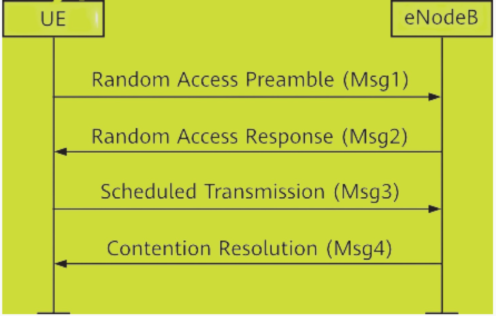
Contention-Based RA Procedure

RA Preamble Transmission (Msg1):
- The UE starts the RA process by sending an RA preamble to the gNodeB (NR base station). The selection of this preamble is done randomly from a pool of available preambles.
- Before sending the RA preamble, the UE obtains the PRACH configuration from the RRCReconfiguration message. This configuration provides the time-domain and frequency-domain information needed for the transmission.

SSB Selection:
- Each Synchronization Signal Block (SSB) has a unique preamble index. The UE selects the SSB with the strongest RSRP (Reference Signal Received Power) that meets or exceeds a predefined threshold. If no SSB meets the required threshold, the UE selects one randomly.
gNodeB RA Response (Msg2):
- After the gNodeB receives the RA preamble, it responds with an RA response (Msg2). This response includes critical information such as timing alignment, which the UE uses for subsequent transmissions.
UE Transmission (Msg3):
- The UE uses the timing alignment information from Msg2 to send Msg3, which includes the UE’s cell radio network temporary identifier (C-RNTI) or other identification information.
Contention Resolution (Msg4):
- The gNodeB sends a Contention Resolution message (Msg4) to the UE, confirming the successful completion of the RA procedure. This message helps resolve any contention that might have occurred if multiple UEs attempted to access the network using the same RA preamble.
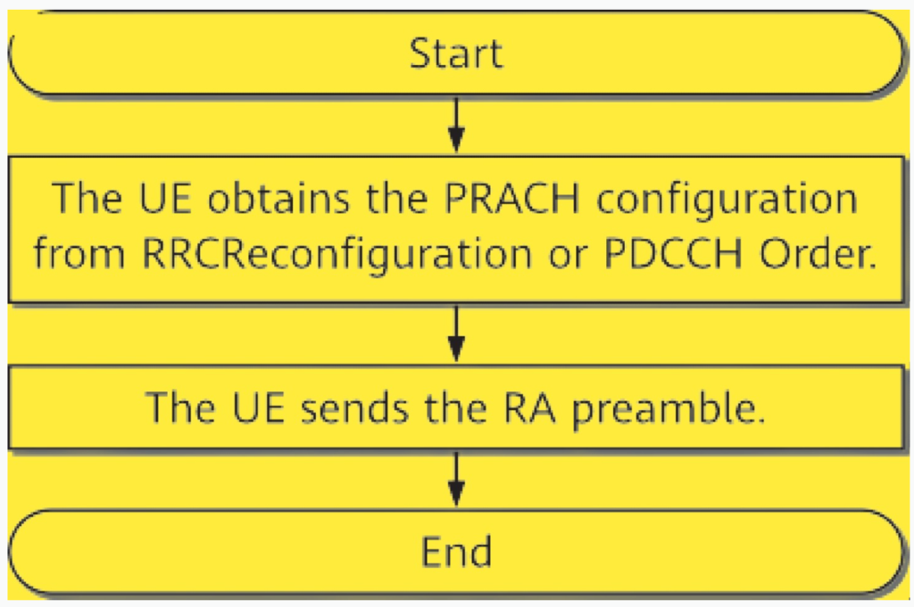
Non-Contention-Based RA Procedure

RA Preamble Allocation:
- In non-contention-based RA, the gNodeB directly allocates a specific RA preamble to the UE. This allocation typically occurs through RRCReconfiguration signaling or via PDCCH (Physical Downlink Control Channel) Order.
SSB Indication:
- Along with the RA preamble, the gNodeB indicates which SSB the UE should use for the RA procedure. This indication is provided through the PDCCH or RRC signaling.
RA Preamble Transmission (Msg1):
- The UE sends the allocated RA preamble to the gNodeB. The transmission timing and frequency are determined based on the PRACH configuration provided by the gNodeB.
gNodeB RA Response (Msg2):
- Similar to the contention-based procedure, the gNodeB sends an RA response (Msg2) back to the UE. This response includes the RA-preamble identifier and timing alignment information necessary for the UE’s next steps.
Monitoring and Transmission (Msg3):
- The UE monitors the PDCCH for the RA response. If it receives a response within the RA response window, the UE considers the RA attempt successful and sends Msg3, which contains timing alignment information for scheduled transmission.
- If the UE does not receive a response within the RA response window, it retries the RA procedure, up to a certain limit. If all attempts fail, the RA process is deemed unsuccessful.
Below table shows initial access comparison between NSA networking and LTE.
