In this article
PURPOSE – This technical engineering specification defines the minimum requirements for the installation of electrical trace heating systems.
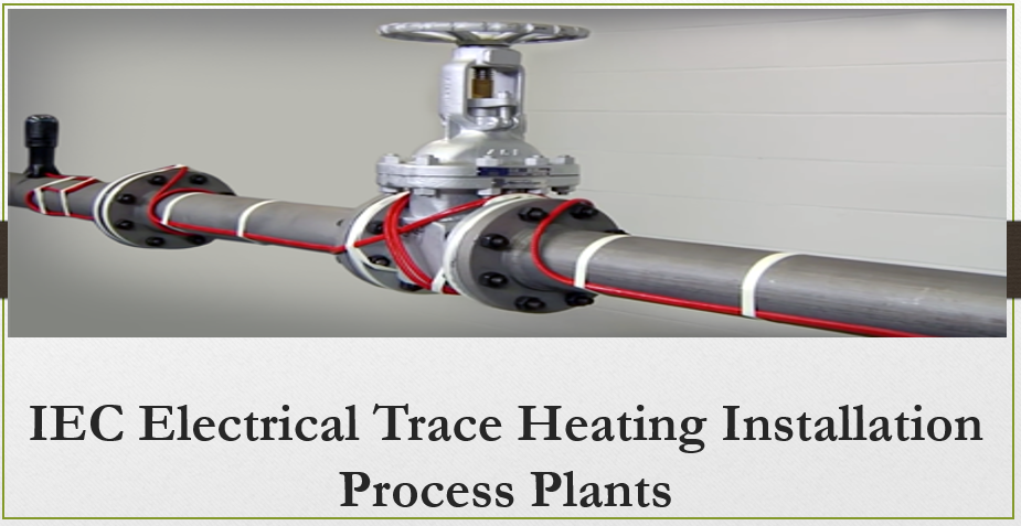
2. IEC Electrical Trace Heating Installation in Process Plants
This technical specification applies to electrical trace heating systems on process plants. This article is limited to the use of electrical trace heating systems for the prevention of freezing or coagulation of fluids, or the malfunction of equipment during normal operation, by application of self-limiting type electric trace heating cables to process plant.
2.3 The supply and installation of thermal insulation is not discussed here.
- RELATED DOCUMENTS
- 3.1 Air Products Engineering Documents
- All equipment covered by this article shall be according to the requirements of the latest edition of the following documents:
- Shipment and Packing Specification for Consolidating Warehouses and Direct Export Shipping
- 4GN90001E Winterisation of Piping, Equipment, Vessels, and Instrumentation
- VDR Vendor Documentation requirements form
- STANDARD ELEC 0002 Electrical Installation Details
- 3.2 British Standards Institute (BSI)
- All equipment for installation in the European Union shall be according to the requirements of the latest edition of the following documents:
- BS EN 60079-14 Electrical apparatus for explosive gas atmospheres
- Part 14: Electrical installations in hazardous areas (other than mines)
- BS 6351: Part 1 Electrical surface heating: Specification for electric surface heating devices
- BS 6351: Part 2 Electrical surface heating: Guide to the design of electric surface heating systems
- BS 6351: Part 3 Electrical surface heating: Code of practice for the installation, testing and maintenance of electric surface heating systems
- 3.3 European Council/Commission Legislative Documents (EC)
- All equipment for installation in the European Union shall be according to the requirements of the latest edition of the following documents:
- 73/23/EEC Council Directive on the Harmonization of the Laws of Member States Relating to Electrical Equipment Designed for Use within Certain Voltage Limits
- 2004/108/EC Council Directive on the Approximation of the Laws of the Member StatesRelating to Electromagnetic Compatibility
- 3.4 International Electrotechnical Commission (IEC)
- All equipment covered by this specification shall be according to the requirements of the latest edition of the following documents:
- 60079 Electrical apparatus for explosive gas atmospheres
- 60800 Heating cables with a rated voltage of 300/500 V for comfort heating and prevention of ice formation
- 3.5 China National Standards (GB)
- Equipment for final installation in the People’s Republic of China shall conform to the following standards, where applicable.
- GB 1207 Voltage transformers
- GB 1208 Current transformers
- GB 6995 Markings for electric cables and wires
- GB 13539 General requirements for low-voltage fuses
- GB 14048 Low-voltage switchgear and controlgear
- GB 3836.15 Electrical apparatus for explosive gas atmospheres Part 15: Electrical installation in hazardous areas (other than mines)
- GB 16847 Requirements for protective current transformers for transient performance
- GB 16916 Residual current operated circuit-breakers without integral overcurrent protection for household and similar uses
- GB 16917 Residual current operated circuit-breakers with integral overcurrent protection for household and similar uses (RCBO)
- GB/T 7676 Direct acting indicating analogue electrical measuring instruments and their accessories
- GB/T 4728.7 Switchgear, controlgear and protective devices
- GB/T 14598 Electrical relays
- GB/T 17627 High-voltage test techniques for low voltage equipment
- 4. DEVIATIONS
- 4.1 No deviations from this specification shall be permitted without the written approval of
- Air Products. The supplier may list exceptions in their quotation for Air Products’ consideration and approval. Without an exceptions list, Air Products will assume the supplier fully complies with this specification.
- 5. GENERAL REQUIREMENTS
- 5.1 Installation Climatic Conditions
- Note: The installation shall guarantee complete protection against the ingress of water when installed in the open without additional protection. This shall include provision to prevent the ingress of moisture during transit of materials/equipment from the contractor’s works and storage before installation on site.
- The following types of equipment/materials shall be provided by the contractor for the installation of the electric trace heating system.
- 5.2.1 Cables
- Frost protection circuit thermostats shall be supplied by the contractor for automatic control of the trace heating distribution board. In addition, all other types of process control thermostats or thermocouples shall be supplied by the contractor.
- Distribution boards shall be supplied by Air Products unless stated to the contrary.
- Minimum Cable Size: The minimum size of power cable to be used shall be 2.5 mm2. Cable shall be 600/1000 V grade polyvinyl chloride (PVC) or cross-linked polyethylene (XLPE) insulated, stranded copper conductors, wire or tape armored, and PVC sheathed to IEC standards.
- 6. DRAWING AND DATA
- 6.1 Electrical Trace Heating Design: Air Products will design the complete electrical trace heating system up to and including the distribution boards. All necessary information to complete the installation work shall be obtained by the contractor from the drawings and documents attached to the technical specification.
- 6.2 Isometric Drawings
- 6.3.1 Company will provide standard drawings showing the typical installation of electrical trace heating cables for the following:
- 6.3.2 In addition, Air Products will provide standard drawings showing the installation details of junction boxes and termination requirements of electrical trace heating cables.
- 6.4.1 Air Products will supply project-specific, one line diagrams of each distribution board showing the following:
- 6.5.1 Air Products will supply a simplified layout identifying the location of the trace heating distribution board and the power cable route to the first electrical trace heating box for each power circuit. The contractor shall be responsible for determining the cable routes from this point on a “site run” principle.
- 6.5.2 The contractor shall mark up the Air Products layout drawings, showing the “As-Built” location of the junction boxes and an interconnection diagram of the junction boxes.
- FIELD TESTING AND INSPECTION
- The contractor shall perform all tests listed in Appendix A. The test results shall be completed and approved by the contractor’s Quality Assurance (QA) department, then handed to the Air Products construction supervisor for acceptance.
- Field testing of insulation resistance and continuity shall be performed with a 500 V megger.
- Insulation resistance from one conductor to shield shall not be less than 10 Megohms, irrespective of the heating cable length.
- The Air Products construction supervisor shall verify that the heating system is being installed according to the required installation specifications, project specifications, and cable manufacturer’s instructions. If there is a conflict, Air Products shall require the contractor to obtain approval of the installation from the trace heating cable manufacturer at the contractor’s expense.
- The contractor may provide their own quality control and test/inspection sheets as an alternative to those identified in paragraph 7.1 above, subject to the approval of Air Products Electrical Design Department.
8. EMC AND LOW VOLTAGE DIRECTIVES
All equipment for final installation in the European Union shall be CE marked for compliance with 73/23/EEC, 2004/108/EC and the Supplier shall provide a Declaration of Conformance or Certificate of Incorporation as applicable for the equipment supplied.
Appendix A
Electrical Trace Heating Installation Test Certificate

| Circuit
No. |
| INSTALLATION RECORDS FOR | ||||||||
| Circuit breaker number: | ||||||||
| Drawing reference number: | ||||||||
| Megger test before Reading insulating (bypass thermostat Initial
if applicable Date |
||||||||
| Megger test after Reading insulating (bypass thermostat Initial
if applicable). Date |
||||||||
| Circuit voltage Panel Connection Terminals | ||||||||
| Insulation completed Initial and sealed Date | ||||||||
| Locations of under insulation Initial components are marked on Date the insulating lagging | ||||||||
Discover more from PAKTECHPOINT
Subscribe to get the latest posts sent to your email.