- PURPOSE
- SCOPE
- APPLICABLE DOCUMENTS
- RESPONSIBILITY
- MANPOWER
- TOOLS & EQUIPMENT
- METHODS / PROCEDURES
- QUALITY CONTROL
- SAFETY PRECAUTION
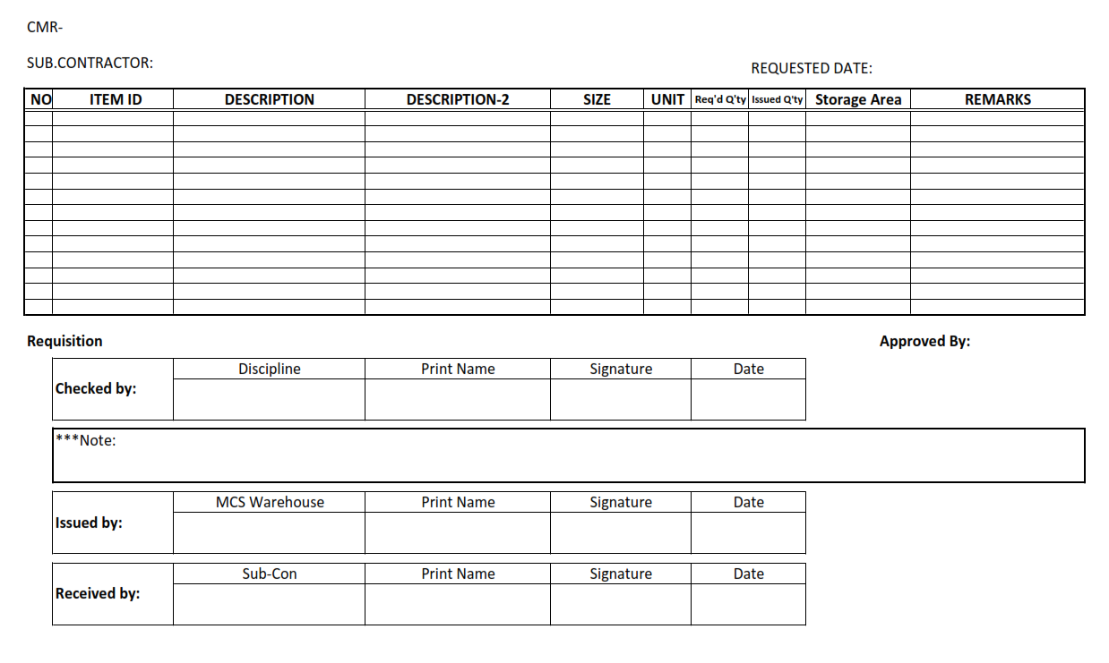
- Construction Material Requisition (CMR).
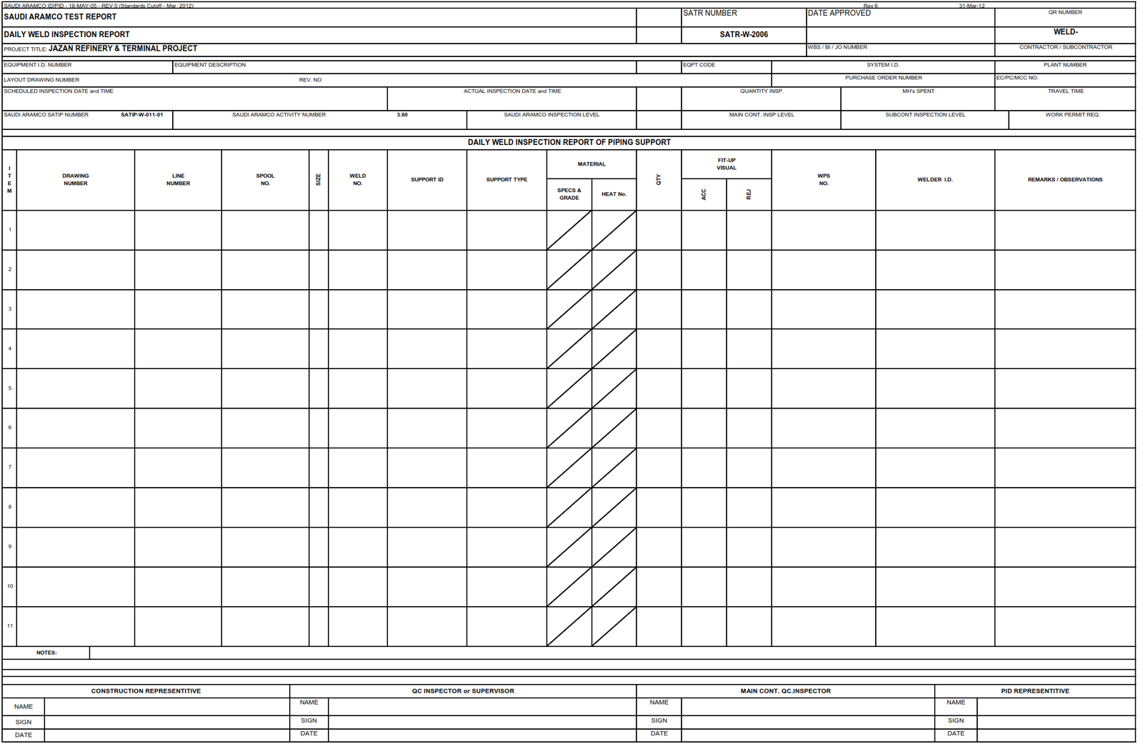
- Daily Weld Inspection Report of Piping Support (DWIR).
- Daily Fit-up Inspection Report of Piping Support (DFIR).
- Job Hazard and Risk Assessment (JHRA).
1.0 PURPOSE
1.0 This method statement shall provide minimum guidelines to carry out the Piping Support Installation activities, procedures.
2.0 SCOPE
This Method Statement covers the procedure of Piping Support Installation for Construction Project.
3.0 APPLICABLE DOCUMENTS
3.1 Project Specifications and Standards
- ASME B 31.1 Power Piping
- ASME Section V Non-Destructive
- ASME 31.3 Process Piping
- ASME Section IX Welding & Brazing Qualification
- ASME D1.1 Structure Welding Code
- SAES-A-206 Positive Material Identification
- SAES-L-105 Piping Material Specifications
- SAES-L-310 Design of Plant Piping
- SAES-L-350 Construction of Plant Piping
- SAES-M-001 Structural Design Criteria for Non-Building Structures
- SAES-W-011 Welding Requirements for on Plot Piping
- SAES-W-016 Welding Special Corrosion-Resistant Materials
- 01-SAMSS-010 Fabricated Carbon Steel Piping
- 12-SAMSS-007 Fabrication of Structural & Miscellaneous Steel
- Schedule “Q” Quality Requirement
4.0 RESPONSIBILITY
4.1 Construction Manager is responsible for implementing HSE and shall study, analyze and schedule all construction activities with his department to include manpower and equipment line up as well as other possible resources required for the successful implementation of the construction work activities. Study all aspects of work procedure as per JV Technical Scope of Work.
4.2 QA/QC Manager has the responsibility to:
4.2.1 Review of all request including Daily Welding Inspection Report.
4.2.2 Managing welder qualification.
4.2.3 Managing control system.
4.2.4 Managing of quality control
4.2.5 Managing inspection and test with regard to support installation.
4.3 Piping Superintendent shall assist Construction Manager in the overall construction activities. Receives and carries out directives and strategies of Construction Manager in various phases of duties assigned by this immediate Supervisor.
4.4 Material Control Manager has the responsibility to:
4.4.1 Receiving and maintaining of material
4.4.2 Control of material stock status before release to construction team.
4.4.3 Issuance of material to support construction.
4.4.4 Request the material receiving inspection to QA/QC team.
4.5 Piping Supervisor shall study and review all necessary documents for the erection works in his area to include, technical scope of work, specification, bill of quantities, planned milestone dates and construction procedure in support to his Piping Foreman. He shall monitor the availability of materials in accordance with the schedules and construction analysis. He shall be directly reporting to the Piping Superintendent. He shall coordinate with other discipline to visualize possible conflicts in the drawings as well as in the schedules to provide other options in preventing unnecessary delays and obstructions.
4.6 The Welding Supervisor and/or Foreman are solely responsible to ensure that all welding works are in conformance with applicable codes, standards, specifications and approved procedures.
4.7 Piping Foreman shall be responsible for the direct work supervision at site and ensure that the work is performed in accordance with JV Technical Scope of Work and latest approved for construction drawings. He shall monitor the availability of materials in line with his required schedule.
4.8 QC Inspector shall be responsible in monitoring and inspection of the work and ensured that the work is performed and properly documented in accordance with project requirements
4.9 Safety Supervisor shall be responsible in monitoring safety aspects and ensuring that the work is done in accordance with JV Safety Standard Procedure. He shall discuss to the workers the characteristics of related materials and status of work area giving reminders as an additional point to injury and incident free environment.
5.0 MANPOWER
5.1 QC Personnel will report directly to QC Supervisor in accordance with Schedule- Q, para.5.7.
5.2 The Piping/Structural Supervisor shall control the overall activity of shop fabrication and he shall be directly reporting to the Construction Manager. The basic manpower under him shall consist but not limited to the following:
5.2.1 Piping Foreman.
5.2.2 Welding Foreman.
5.2.3 Pipefitters.
5.2.4 Steelworkers.
5.2.5 Welder.
5.2.6 Crane Operator (Aramco Certified).
5.2.7 Forklift Operator (Aramco Certified).
5.2.8 Rigger (Aramco Certified).
5.2.9 Trailer truck Driver.
5.2.10 Helper.
5.3 Safety Supervisor.
5.3.1 Safety Engineer.
Structural/Welding Supervisor & Safety Officer prior to use in the fabrication construction area. These includes but not limited to:
6.1.1 Tools, Jigs Instrument
- Ball Hammer
- Wrenches
- Magnetic/spirit level
- Sturdy work bench
- Chain Puller
- Bevel gauge
- T-square
- Straight edge
- Frames
6.1.2 Equipment
- Mobile crane
- Forklift
- Angle grinder
- Pencil grinder
- Cutting outfit
- Boom truck
- Cut-off wheel
- Radial cutter
- Generator set
- Trailer truck
- Welding Machine.
7.0 METHODS/ PIPING SUPPORT INSTALLATION PROCEDURE:
7.1 General Preparatory Works (by other sub-contractor)
7.1.2 Make production plan considering material availability and area priority.
7.1.3 Issuance of isometric drawing or support style list to support fabrication shop.
7.1.4 Request raw material support to material warehouse
7.1.5 Receiving support material from warehouse and perform receiving inspection.
7.1.6 Cutting and end preparation
7.1.7 Fit-up and tack welding
7.1.8 Shop Welding.
7.1.9 Shop Inspection – Fabrication shop shall be offered for inspection to SAPMT/PID before start of fabrication.
7.1.10 Blasting and primer painting work at paint shop.
7.1.11 QC documentation for shop.
7.1.12 Release support and store on stock yard.
7.1.13 Support issuance to field support team.
7.2 Storage and handling material
7.2.1 Material shall be stored separately by its type and specification and it shall be marked according to its designed color.
7.2.2 Certificates verifying that materials or items used in the fabrication comply with purchaser’s requirement. Certificates for each category of material shall be submitted.(by other sub-contractor)
7.2.3 Materials shall be maintained to comply with any warranty conditions imposed by the manufacturer.(by other sub-contractor)
7.2.4 Nylon slings shall be used for handling stainless steel materials and straps.
7.2.5 Storage areas for stainless steel materials shall be separate from the areas where carbon steel material is stored. Walking on the austenitic stainless steel material shall be avoided (ref. PFI Standard ES-43 para 2.4 & 2.7).
7.2.6 Only 300 series stainless steel brushes shall be used on austenitic steel materials (ref. PFI Standard ES-43 para. 3.4).
7.3 Material Receipt, Storage and issue for pipe support (for field fabricated)
7.3.1 Material control shall verify that material received conform to the applicable requirements. All the material shall be stored in safe/secure area accessible to the SAACO/JV or Company Representative.
7.3.2 During loading and unloading of material, Certified Crane and Forklift Operators are to engage for the safety operation.
7.3.3 All materials shall be stored in a planned manner for easy identification of materials and issue.
7.3.4 Materials upon receipt shall be checked for quantity by Warehouse personnel. QC Inspector to conduct material receiving inspection as per SATIP for SAACO supplied materials only.
7.3.5 Make sure that raw material are properly marked & recorded with its applicable identification marked and code numbers as per project requirements.
7.4 Releasing of pipe supports to Field Operation
7.4.1 After required inspection has been done and accepted documentation shall be prepared, completed by the QC inspector prior to release the pipe support for installation.
7.4.2 The QC Inspector shall prepare the pipe support release sheet indicating the tag number of pipe support.
7.5 Control of Pipe Support Installation
7.5.1 General
7.5.1.1 As a general practice, appropriate adjustment/ modification/ addition of support shall be made by construction according to the actual field conditions, especially for small bore piping.
7.5.1.2 All pipe support must be installed as per specification and drawing, isometric drawing,
7.5.1.2.1 Piping arrangement drawing
7.5.1.2.2 Pipe support standard drawing
7.5.1.2.3 Special pipe support drawing
7.5.1.2.4 Pipe support index.
7.5.1.3 Piping shall be properly anchored and guided before pressure testing.
7.5.1.4 Support should be fabricated and installed prior to the piping installation, and use of temporary supports is to be minimized.
7.5.1.5 In case temporary support is required, the support arrangement shall be measure so that they have sufficient bearing strength and stable supporting for the piping system.
7.5.1.6 All temporary support shall be removed before hydro test.
7.5.1.7 Field welded support shall be set correctly in place and adjusted to the final position before welding.
7.5.1.8 For sliding supports, bearing surfaces shall be sufficiently clean to secure unrestricted movement.
7.5.1.9 Clamp bolts on clamp shoe type support should be checked as per standard pipe support drawing.
7.5.1.10 Support shall not be welded to the equipments unless otherwise specified.
7.5.1.11 In case that stainless steel piping without insulation is resting on the steel structure, pipe rack or piping support directory, stainless steel plate shall be installed between piping and structure to avoid direct contact, even if this information is not shown in support drawing.
7.5.1.12 For installation of concrete expansion anchor bolts, it shall be performed in accordance with vendor information.
7.5.2 For locking devices such as bolts & nuts.
7.5.2.1 Support height shall be adjusted to the actual field condition. All threaded connections, except height strength bolts, shall be secured by locking devices to prevent loosening during service.
7.5.2.2 If possible bolt/stud shall be locked in place with double nut. (Jam nut) a nut tack welded to the bolt/stud shaft may serve as a locking device and may use except where welding is prohibited on the bolt material.
7.5.3 Installation of spring hangers
7.5.3.1 Installation of constant and variable spring hangers shall be in accordance with the manufacturer’s instruction, the design drawing and the procedure.
7.5.3.2 Spring hangers shall be easily accessible after installation within the limits of possible, and the scales shall be unobstructed and visible.
7.5.3.3 Ensure that the travel stops are engaged and maintained thus on all spring hangers until the piping system are place in service, except during such time of checking and marking adjustments on the spring hangers.
7.5.3.4 Spring supports shall be installed with the spring locks in place and the travel shall be cold set position.
7.5.3.5 Spring locking plates or pins shall not be removed until hydrostatic testing and insulation of piping system has been completed.
7.5.3.6 If the spring force on empty line will cause possible damage to connected strain sensitive equipment, spring locks shall remain in position until the line is filled with the actual service fluid.
7.5.3.7 Relevant support and support drawing shall bear the warning”block against empty position” and lock shall be attached with the spring support during operation. The travel stops on spring hangers shall be engaged during filling, testing and draining of pipe systems for hydro test.
7.5.4 Base mounted supports
7.5.4.1 Required between concrete surface and structural pipe support attachment plates. All grout works shall be performed in accordance with relevant work procedure.
7.5.4.2 Non-shrink grout shall be mixed and place in according with manufacturer’s written instruction.
7.5.5 Wall or ceiling mounted supports
7.5.5.1 Pipe support base plates shall be mounted flat against the wall or ceiling. Irregularities on the wall or ceiling surface that prevent flush mounting on the base plate, such as fins, protrusions, and excessive roughness shall be removed by grinding.
7.5.5.2 Grouting is not required except when depression, grooves, holes or other cavities under the base plate that are not amenable to removal by grinding. It should be filled with grout before mounting the base plate.
7.5.6 Hanger rod and turn buckle installation
7.5.6.1 Threading of hanger rods shall be performed in accordance with ASME B31.3 para321.1.5, thread designation UNC and, shall have a minimum of three full thread exposed when the nut is tightened on the hanger rod threads.
7.5.6.2 Lubricant for threaded portion of rod is not required. For galvanized threads cut in the fields, the threaded portion of the rod shall have touch-up coating.
7.5.6.3 To compensate for pipe elevation discrepancies, hangers are usually provided with means to permit vertical adjustment during and after installation.
7.5.6.4 Threaded devices such as turnbuckles, clevises, etc. are acceptable, provided that after the adjustment the result is no less than full thread engagement.
7.5.6.5 Suitable locking devises shall be used at all threaded connections of the hanger assembly i.e “double nuts” (ref. SAES-L-310 para 14.3.6).
7.5.7 Shoe or pads installation
7.5.7.1 For shoes shall be welded to piping with careful way avoiding any welding defects. Special care must be taken to the anchor points, as they are to be heavily loaded.
7.5.7.2 Shoes pads for low alloy steel piping shall be of the same materials as the pipes. In case of lines having shoe or saddle support, site
measurement between distances of supports maybe given and marked on the assembly. The supports are then welded on the spool assembly on the ground. In case of lines having guide or anchor the supports are to be welded in position. All supports or saddle welded to main pipe shall undergo the same testing requirement as of that main pipe.
7.5.7.3 “Saddle-type supports with pads shall be provided for piping 30-inch NPS and larger” (ref. SAES-L-310 para 16.2.4).
7.5.8 Modification Work
7.5.8.1 If material received from pipe support fabricator has a discrepancy on approved for construction drawings and specs, pipe support need to modify and return defected fabricated support at shop for modification.
7.5.8.2 For minimal modification SAACO will rectify at site the defective material as per required drawing and specification with issuance of site instruction.
7.5.9 Welding and welding attachment
7.5.9.1 All welding shall be in accordance with approved welding procedure specification.
7.5.9.2 The material of the attachment which is directly welded to the pipe shall be as shown other pipe support detailed drawings.
7.5.9.3 Welding must be carried out by qualified welder in accordance with approved welding procedure specification.
7.5.9.4 Material traceability report shall be recorded the heat-number of attachment and verified by QA/QC inspector and Contractor’s inspector for LCTS, stainless steel and alloy steel.
7.5.9.5 Daily welding inspection report shall be signed off by QC inspector after visual inspection.
7.5.9.6 All welds will be identified on the isometric drawing and shall be inspected by welding inspector and recorded in daily welding inspection report.
7.5.10 Post Weld Heat Treatment
7.5.10.1 Performance of PWHT shall be in accordance with post weld heat treatment procedure.
7.5.10.2 QA/QC shall review PWHT record and submit to owner for review.
7.5.11 Non-Destructive Examination
7.5.11.1 The management and request of NDE (MT/PT) shall be in accordance with NDE control procedure.
7.5.11.2 QA/QC shall review NDE (MT/PT) record and submit to owner for review.
7.5.12 Touch-up painting
7.5.12.1 Touch-up paint the pipe support according to painting specification and procedure.
8.0 QUALITY CONTROL
8.1 All fabricated supports shall be inspected by JV Inspector base on applicable project specifications listed in item 3.1. Testing and inspection shall be coordinated with JV by SAACO QC Inspector.
8.2 Inspection of welding shall be performed in accordance with the Structural Welding Code, ANSI/AWS D1.1/D1.1M. Refer to 12-SAMSS-007 sec. 7.6.
8.3 SAACO QC Inspector shall be assigned to ensure the quality control and assurance requirements of the project.
8.4 SAACO QC Inspector shall be responsible to conduct all required inspection/documentation and to assure that all applicable requirements, codes and standards are complied with.
8.5 Contractor has to utilize the applicable SAIC for every activity.
9.0 SAFETY PRECAUTION
9.1 Construction Manager/Supt./Supv./FM shall be responsible for the implementation of this procedure and the required orientation necessary for the work force.
9.2 All rigging equipment shall be in good condition and possess a valid certification from authorized certifying and inspection departments.
9.3 Safety Supervisor shall monitor compliance of the entire working crew to safety procedures until the work is fully completed.
9.4 Toolbox meeting shall be conducted by Structural Fabrication Supervisor daily so that the work activities will be properly coordinated to all concerned and all safety infraction will be acted immediately.
9.5 All necessary personal protective equipment (PPE) shall be provided and to be worn at all times in accordance with site Safety Procedure.
9.6 Fabrication shop shall be kept in a clean tidy manner, in accordance with Site Housekeeping Procedure.
9.7 Job Hazard and Risk Assessment (JHRA) of this method statement shall be disseminated and explained to workers for safety awareness.
9.8 SAACO shall make sure that the Piping Support Installation is incident and injury free.
9.9 All workers shall wear as a minimum PPE required below.
- Safety Helmet.
- Safety glasses.
- Safety Shoes.
- Gloves.
- Mask, if required to prevent inhalation of dust and welding gas.
- Ear plug, if required by conditions.
- Machinery like grinding wheel cutter shall have a protection method.
- Safety shall be requested and carried out in accordance with safety procedure.
Construction Material Requisition (CMR)
Daily Weld Inspection Report of Piping Support (DWIR)
Daily Fit-up Inspection Report of Piping Support (DFIR)

Job Hazard and Risk Assessment (JHRA)
Discover more from PAKTECHPOINT
Subscribe to get the latest posts sent to your email.