In this article
- Electric Motor System Diagnostics Procedure
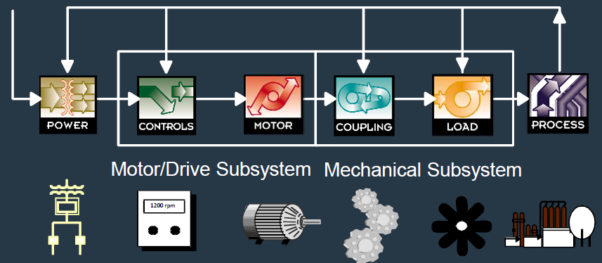
- What is a Motor System?
- The Electric Motor System
- Three-Phase Input Power Process Mechanical and Electrical Feedback
- Motor System Faults
- some common faults found within a motor system
- MCC – Controls and Disconnects
- Electric Motor (Mechanical)
- Load (Fans, Pumps, Compressors, Gearboxes, Etc.)
- About Motor Electrical Faults
- o Overloading
- o Frequent start/stop cycling
- o Vibration
- o Contamination
- o Age, Heat, VF Drives
- Other Types Of Electrical Faults
- Meg-Ohm-Meter & Volt/Ohm Meter
- When Used for Elec Motor Testing*
- Typical Electrical Contractor Today
- Contractor with MCA and ESA
- Why Offer An Electrical Motor Testing Program?
- failure
Electric Motor System Diagnostics Procedure
• The reliability and energy consumption of electric motors and the systems they drive has a direct financial impact to industrial and commercial enterprises.
• We will discuss the financial justification for a motor testing program, a general discussion of De-energized and Energized testing methods, and ideas for selling the service.
• Electrical Motor System testing is becoming an important part of a successful rotating equipment reliability testing program
What is a Motor System?
The Electric Motor System
Three-Phase Input Power Process Mechanical and Electrical Feedback
Motor System Faults
some common faults found within a motor system
Incoming Power
• Power Quality
o Harmonics (Voltage and Current)
o Over/Under Voltage
o Voltage Unbalance
o Power Factor
o Overload
Transformers
• Transformer Faults
o Insulation to Ground
o Winding Shorts
o Loose Connections
o Electrical Vibration
MCC – Controls and Disconnects
• MCC/Disconnect Problems
o Loose Connections
o Faulty Contacts
o Faulty Coils
o Faulty VFD
o Faulty Starter
o Bad PF Correction Capacitors
Cables (Before and After Controls)
• Cable Faults
o Thermal Breakdown
o Contamination (especially underground feeders)
o Shorts and Grounds
o Open
o Physical Damage
Electric Motor (Mechanical)
• Mechanical Faults
o Bearings
o Bad Shaft/Brg Housing
o Vibration
Electric Motor (Electrical)
• Electrical Faults
o Winding Shorts
o Insulation to Ground
o Contamination/Thermal Stress
o Rotor Faults
o Air Gap Faults
Coupling (Direct and Belted)
• Faults
o Misalignment
o Unbalance
o Belt/Insert Wear
o Tension Issues
o Sheave Wear
Load (Fans, Pumps, Compressors, Gearboxes, Etc.)
• Load Faults
o Worn parts (I.e. seals)
o Broken components (gears, fan, impeller blades, etc.)
o Bearings, etc
Where Electrical Faults Can Begin
• End turns of windings
o Stresses are greatest
o Insulation is weakest
o Most exposed to contamination
About Motor Electrical Faults
- They start small and get worse
- They always end in failure
- Contributing factors
o Overloading
o Frequent start/stop cycling
o Vibration
o Contamination
o Age, Heat, VF Drives
Other Types Of Electrical Faults
- Open Phases
- Broken/Cracked Rotor Bars
- Air gap (eccentricity)
- Blown Capacitors
- Poor Connections
- Cable Faults
- Overload, Fuses, etc.
Meg-Ohm-Meter & Volt/Ohm Meter
When Used for Elec Motor Testing*

* Common electrical testing instruments **Coil faults- turn to turn & coil to coil
Combined Technology Approach
Typical Electrical Contractor Today
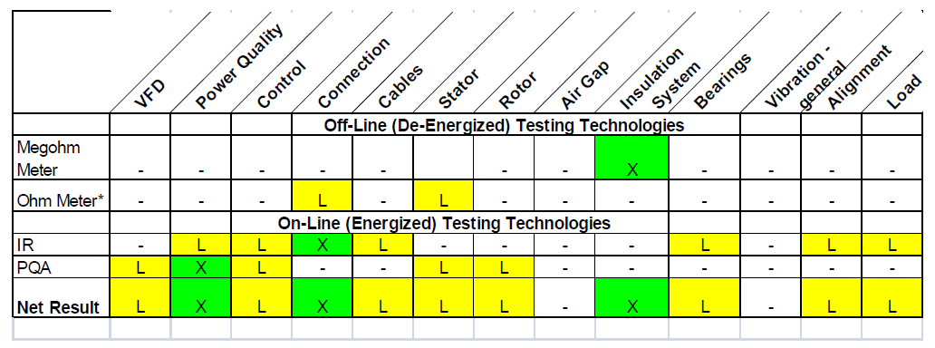
Green indicates that a developing fault can be both detected and trended for Predictive Maintenance purposes.
Yellow indicates a fault can be detected, but is difficult to trend or cannot be detected at an early stage.
* When using a typical DMM to measure resistance.
Combined Technology Approach
Contractor with MCA and ESA
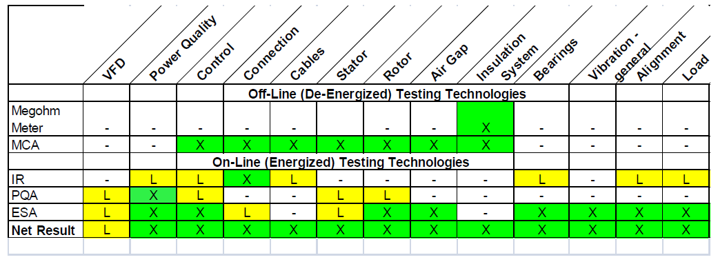
Green indicates that a developing fault can be both detected and trended for Predictive Maintenance purposes.
Yellow indicates a fault can be detected, but is difficult to trend or cannot be detected at an early stage.
Why Add Motor Testing?
- Generates additional billable hours for your business
- Improves your customers’ equipment reliability
- Provides a more accurate assessment of your customers’ equipment when compared to what you are doing now
Why Offer An Electrical Motor Testing Program?
- Many of your customers have motor system reliability issues
- Some will not have the resources to support an in-house motor testing program
- Some of your customers will gladly pay for this service
- Motor testing equals extra billing $$
- Multi-Technology Approach to Motor Diagnostics
o Electrical motor testing will also improve your ability to detect and eliminate causes of system
failure
- Use De-Energized MCA and Energized ESA testing to validate findings from Infrared & Power Analysis test methods
Why Your Company for Electrical Motor Diagnostics?
- Improve Rotating Equipment Reliability
- Lower Your Operating Costs
- Lower Energy Consumption
- Improve Product Quality
- Increase Company Profits
- Improve Employee Safety
- Reduce Reactive Repair Time When Equipment Does Fail
Discover more from PAKTECHPOINT
Subscribe to get the latest posts sent to your email.
I got what you mean , regards for posting.Woh I am happy to find this website through google.