In this article
- What is Node Analysis?
- Basic Concepts
- Steps for Node Analysis
- Step-1: Identify All Nodes
- Step-2: Assign Node Voltages
- Step=3: Apply Kirchhoff’s Current Law (KCL)
- Step-4: Solve the System of Equations
- Example Circuit for Node Analysis.
- Step-by-Step Solution
- Apply KCL to Each Node
- Node ( V1 ):[(V1 – 42 / 8) + (V1/4) + (V1 + 10)/6] = 0
- V1 = 6.61 V
- Summary.

Node Analysis, also known as Nodal Voltage Analysis, is a method used to determine the voltage at various points (nodes) in an electrical circuit. This technique is especially useful for analyzing circuits with multiple nodes and branches, as it simplifies the process by focusing on voltages rather than currents.
What is Node Analysis?
Basic Concepts
- Node: A point in a circuit where two or more circuit elements are connected.
- Reference Node (Ground): A node selected as the zero-voltage point against which all other node voltages are measured.
- Node Voltage: The electrical potential difference between a node and the reference node.
Steps for Node Analysis
Step-1: Identify All Nodes
Label each node in the circuit. Choose one node as the reference node (ground) and assign it a voltage of 0V.
Step-2: Assign Node Voltages
Assign a variable for the voltage at each node relative to the reference node (e.g., ( V1, V2, ……, VN).
Step=3: Apply Kirchhoff’s Current Law (KCL)
For each node (except the reference node), write a KCL equation stating that the sum of currents leaving the node is zero. Use Ohm’s Law (( I = V/R )) to express the currents in terms of node voltages.
Step-4: Solve the System of Equations
Solve the simultaneous equations obtained in the previous step to find the node voltages.
Example Circuit for Node Analysis.
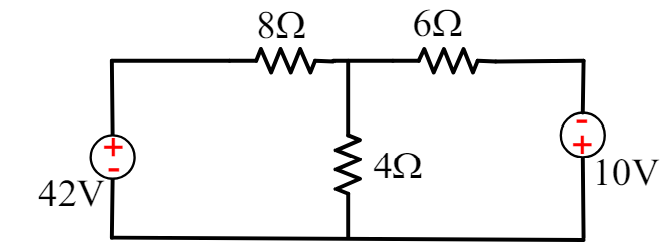
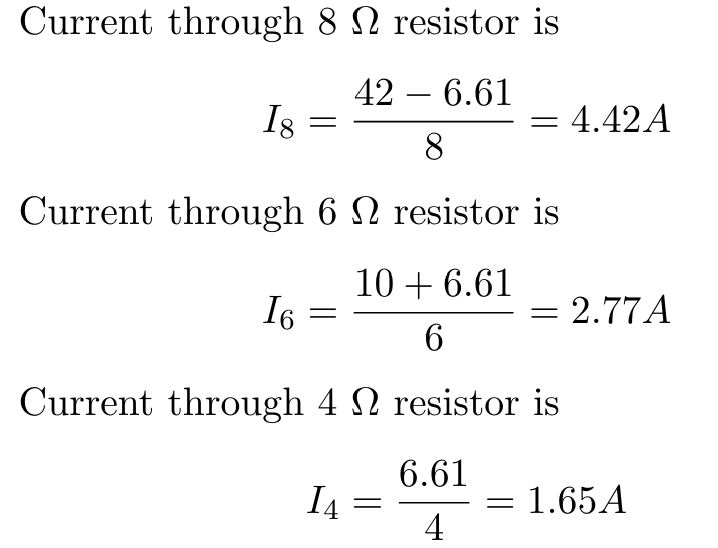
Consider a electronic circuit with three resistors and two voltage sources. Determine all branch current by node analysis.
Step-by-Step Solution
- Identify All Nodes:
There are two nodes to consider: V1 and Choose the bottom node as the reference node (GND).
Apply KCL to Each Node
Node ( V1 ):[(V1 – 42 / 8) + (V1/4) + (V1 + 10)/6] = 0
[0.125 + 0.25 + 0.167] V1 − 5.25 + 1.67 = 0
V1 = 6.61 V
Summary.
Node Analysis simplifies circuit analysis by focusing on node voltages rather than branch currents. By following these steps of identifying nodes, assigning voltages, applying KCL, and solving the resulting equations, you can more confidently find the voltages at various points in the circuit.
Advantages of Node Analysis
- Reduces Complexity: By focusing on node voltages, Node Analysis often requires fewer equations than other methods.
- Scales Well: Particularly effective for large, complex circuits with many nodes and branches.
- Systematic Approach: Provides a clear and methodical way to analyze electrical circuits.
Next Steps
In the next tutorial, we will delve into examples of Nodal Voltage Analysis applied to more complex circuits, illustrating how to handle circuits with dependent sources and multiple voltage sources.
Discover more from PAKTECHPOINT
Subscribe to get the latest posts sent to your email.