In LTE networks, the concept of network accessibility requires the use of different performance counters compared to those in 2G and 3G radio access networks. While RRC (Radio Resource Control) connection setup counters in LTE remain almost identical to those in 3G UMTS, the term “call establishment” needs to be redefined within the all-IP environment of E-UTRAN (Evolved Universal Terrestrial Radio Access Network) and EPC (Evolved Packet Core).
LTE Optimization of Accessibility KPI.
Redefining “Call” in LTE Networks.
In traditional circuit-switched networks, a “call” referred to a voice communication session. However, in the IP-based architecture of LTE, the term “call” is no longer used in 3GPP (3rd Generation Partnership Project) standard documents. Despite this, it is still commonly used in the field of drive testing, network operations, maintenance, and performance measurement. In this context, a “call” typically encompasses all signaling messages and payload data associated with a single subscriber’s connection.
A “call” in LTE can be defined as a single RRC connection between the User Equipment (UE) and the network. This definition aligns with the concept of a “call drop” in the radio access network, indicating the loss of connection between the UE and the network. Within such a “call,” multiple service flows and bearers can be active, each characterized by a unique set of Quality of Service (QoS) parameters. The 3GPP has defined nine different QCI (QoS Class Identifier) values to cater to the most common service requirements.
Aggregating Accessibility Performance Counters.
To evaluate network performance effectively, it is useful to aggregate accessibility performance counters at two levels: the subscriber level and the service level.
- Subscriber Level: Aggregating performance counters at this level allows for the computation of “call setup” Key Performance Indicators (KPIs) that reflect the user’s experience. This includes metrics such as call setup success rate and call drop rate.
- Service Level: Aggregating counters at this level provides a network-centric view for network managers, enabling them to assess how well different services are performing within the network.
1. Random Accessibility Failures.
In LTE networks, monitoring random access procedures has become much easier with the use of radio interface testers and eNodeB trace ports. This level of monitoring wasn’t possible with older 2G and 3G RAN systems.
A key performance indicator (KPI) for evaluating random access success can be defined as:
Low values for this KPI indicate significant issues on the radio interface. This is because the RRC Connection Request and MAC Random Access Response messages are the first messages exchanged over the uplink shared channel (UL-SCH) and downlink shared channel (DL-SCH) in a cell. If there are transmission problems, the random access procedures are the most likely to fail. Such failures have a high impact on users, as they prevent network access, which is immediately noticeable.
2. RRC Accessibility Failures.
In LTE, Signaling Radio Bearers (SRBs) are established when a Radio Resource Control (RRC) connection is set up between the User Equipment (UE) and the eNodeB (eNB). The process of setting up an RRC connection involves sending several messages between the UE and the eNB.

The UE starts by performing initial cell selection to find the best suitable cell for radio access. After this, it sends an RRC connection request message to the eNB. This message includes the UE identity and an establishment cause, which indicates the type of connection being requested. The types of connections can be mobile-originating signaling, mobile-originating data calls, mobile-terminating connections, emergency calls, or high-priority access calls. However, it does not indicate the specific service to be used, making it impractical to aggregate RRC accessibility counters based on the service level.
Once the eNB receives the RRC connection request, it should respond with an RRC connection setup message. If the connection is successfully established, the UE will reply with an RRC connection setup complete message.
To measure the success of this process, the RRC connection setup success ratio can be calculated for each cell using the following simple equation:
RRC Connection Blocking and Failure Ratios.
n LTE, the eNodeB (eNB) can respond to an RRC connection request from the User Equipment (UE) in different ways. If the eNB decides to block the connection request, it sends an RRC Connection Reject message. Unlike the same message in 3G UTRAN, this reject message does not include a cause value but instead specifies a wait time value (1–16 seconds) to help manage the load on the eNB by preventing a flood of RRC connection requests.
When the UE sends an RRC Connection Request, it starts a timer known as T300. If the UE does not receive an RRC connection setup message before T300 expires, it will not resend the RRC connection request. Instead, the UE resets the MAC layer, releases the MAC configuration, and informs the upper layers (e.g., NAS signaling) about the failed attempt. These upper layers then decide if and when to send a new RRC Connection Request. Every single RRC connection request message is counted as a single RRC connection establishment attempt.
To calculate the RRC blocking ratio, you can use the following formula:
It’s essential to distinguish between different failure cases of the T300 expiry for network troubleshooting and optimization. Two primary scenarios exist:
- eNB does not respond before T300 expires: Here, the eNB receives the RRC Connection Request but does not send either an RRC Connection Setup or an RRC Connection Reject before T300 expires. This often indicates an issue within the eNB, such as processor overload. To manage this, the eNB should block access for UEs when a critical limit is reached and increase the wait time in the RRC Connection Reject to balance the signaling load.
- UE does not respond with RRC connection setup complete: In this case, the eNB sends the RRC Connection Setup message, but the UE does not send back the RRC Connection Setup Complete message. This is typically due to transmission errors on the downlink (DL) radio interface, such as weak DL signal levels or interference. For weak signals, especially if the UE is at the cell edge, it’s essential to verify and possibly adjust the settings for the Physical Control Format Indicator Channel (PCFICH) and the DL-SCH. If interference is the issue, the efficiency of the scheduler needs to be investigated.

To compute the overall RRC accessibility failure ratio, use the following formula:
3. Call Setup Failures.
In LTE, a “call” can be understood as a single radio connection between the User Equipment (UE) and the network, used to transmit data through various bearers and service flows. Failures that prevent a UE from connecting to the network and enabling Public Data Network (PDN) connectivity are known as “call setup failures.”
According to 3GPP 24.301 “NAS Protocol for Evolved Packet System (EPS),” when a UE fails to attach to the network, a PDP connection reject message should be sent to ensure proper transitions of EPS Mobility Management (EMM) and EPS Session Management (ESM) states within the UE’s NAS signaling entity.
Failures in call setup often occur due to issues in the Evolved Packet Core (EPC). Common problems include the failure to establish GPRS Tunneling Protocol (GTP) tunnels for the default EPS bearer or failures in the location update procedure between the Mobility Management Entity (MME) and the Home Subscriber Server (HSS). Errors in the Stream Control Transmission Protocol (SCTP) transport can also impact network performance significantly.

Location Update Failures
A typical location update failure doesn’t always indicate a network issue. Sometimes, access restrictions are intentional, such as when a home network operator lacks a roaming agreement with the visited network. In such cases, the attach request is rejected to avoid unbillable roaming services. Communication issues between the visited MME and the home network’s HSS can also lead to failures, often due to high latency on the link. The cause value “network failure” is used in these situations, though it doesn’t always originate from the core network. Network failures can also occur if security functions in the E-UTRAN cannot be activated as required, highlighting the need for intelligent network management tools to accurately identify the root cause of such failures.

In roaming scenarios, communication failures between the visited Mobility Management Entity (MME) and the home network’s Home Subscriber Server (HSS) are common. From experience with 2G and 3G networks, we know that high latency on the link between MME and HSS can delay the Update Location Response (DIAMETER or MAP), causing it to arrive too late. When this happens, the “network failure” cause value is typically signaled in the attach reject message.
However, it’s important to note that not all “network failures” originate in the core network. This cause value is also used when security functions in the Evolved Universal Terrestrial Radio Access Network (E-UTRAN) cannot be activated as required. Therefore, distinguishing the true location and root cause of “network failures” necessitates an intelligent network management and troubleshooting tool. Such a tool should be capable of accurately identifying and reporting where and why these failures occur.

Chain Reactions from Initial Failures
The initial attach procedure is interconnected with many other signaling procedures in the E-UTRAN and EPC. Failures in a specific network element or signaling link often trigger a chain reaction, impacting overall network performance. For instance, if the initial context setup procedure on the S1 interface between the MME and eNodeB fails, it can lead to further complications in the network.
Understanding these aspects of call setup failures is crucial for optimizing LTE networks and ensuring reliable connectivity for users. Proper network management and troubleshooting tools are essential to diagnose and address these issues effectively.
Handling Initial Context Setup Failures in LTE
When the eNodeB (eNB) fails to set up the initial context, it triggers an Attach Reject message with a possible cause of “network failure,” depending on the MME software implementation. This rejection leads to a PDP Connection Reject as well. Consequently, any GTP tunnels on S1-U and S5 that were already established must be deleted using the GTP-C delete session procedure on the S11 signaling link between the MME and the Serving Gateway (S-GW), and on S5 between the S-GW and the PDN-GW. Since the UE’s location was updated in the HSS, it’s necessary to delete this entry and mark the UE as “not reachable” in the HSS database. The signaling procedure used to notify the HSS of this new state is the purge UE procedure.

Even if the UE successfully attaches to the network, another potential error affecting PDN connectivity might occur. After a successful attach, the activation of the default bearer might fail. This issue is usually due to problems in the UE itself. All handsets undergo rigorous testing before market release, making such failures rare but possible. If the UE fails to confirm the successful activation of the default EPS bearer, it will send an activate default EPS bearer failure message. As a result, the UE remains attached to the network (NAS state: EMM Registered) but does not have an active bearer (NAS state in UE: ESM Bearer Context Inactive).
The MME will attempt to resend the Activate Default EPS Bearer Request up to four times. If these attempts fail, the MME may detach the UE, requiring it to re-register with the network.
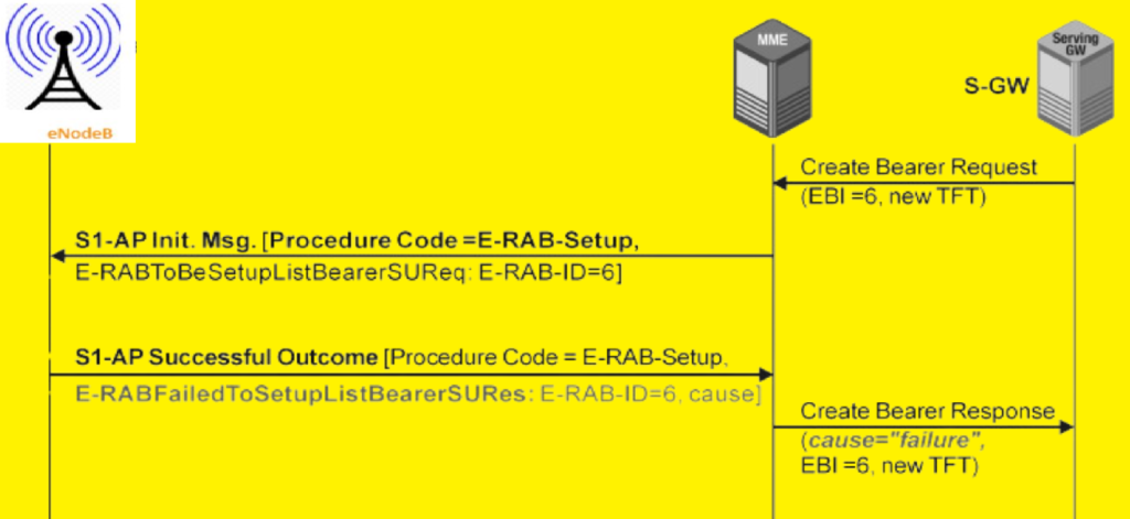
4. Dedicated Bearer Setup Failure in LTE.
A dedicated bearer setup failure happens when a specific service’s access is blocked for a subscriber. This is crucial for measuring user experience, and these failures should be tracked using subscriber IDs for generating customer-centric reports. Additionally, performance counters for dedicated bearer setup should be aggregated based on service level, defined by the embedded QoS parameters in the bearer setup request, and location level, identified by tracking area and E-UTRAN cell ID.
Interestingly, the message name for a bearer setup failure is “Successful Outcome.” This naming convention, also used in UTRAN with the RANAP outcome message, confirms successful setup or failed setup for multiple Radio Access Bearers (RABs). Hence, in S1AP, the message is called “Successful Outcome” even if the E-RAB could not be established.
Typical reasons for failed E-RAB setup include drops in the radio connection before RAB establishment completion and the eNB’s inability to provide necessary resources for the requested service, such as supporting the desired bit rates. Resource limitations often stem from the eNB’s processing power and system memory, particularly on “channel cards” which allow hardware scalability based on expected traffic. If the eNB’s hardware is inadequate, it will lead to error messages with cause values like “not enough user plane processing resources,” especially during peak traffic hours.
5. Paging Failures in LTE.
Analyzing paging failures in LTE requires a detailed approach rather than a simple KPI due to the unique tracking area concept of E-UTRAN. Unlike 2G and 3G RAN where paging messages are sent to all cells within a Location Area Code (LAC), in E-UTRAN, the messages are sent to a few cells within a tracking area, allowing for more precise location tracking of handsets.
A KPI for paging failure ratio at the cell aggregation level may not provide accurate insights since a UE can camp on only one cell. Therefore, storing the subscriber IDs of UEs that did not respond to paging and investigating their last known activities and locations can provide better understanding. Common reasons for paging failures include defective UEs that go out of order without detaching from the network, and UEs that perform cell reselection to 3G or 2G cells without properly updating their location to the network.
To address paging failures, investigate the following:
- Defective handsets
- Insufficient coverage
- Incorrect settings for broadcast cell reselection parameters like S0 criteria
Monitoring both 3G and 4G radio access networks is crucial due to the interworking between these technologies. UEs toggling between UTRA CELL_PCH, URA_PCH, and E-UTRA without proper notifications can cause paging failures in the 3G network and performance degradation in both 3G and 4G networks. Keeping a close watch on these transitions will help in mitigating accessibility failures and maintaining network performance.
6. Accessibility Delay Measurements.
In LTE, accessibility issues aren’t always detected by failure messages from protocol entities. Some problems may not block accessibility procedures but cause delays that are unacceptable. Given that minimizing access delay is a key goal in 3GPP specifications, measuring these delays is crucial for benchmarking E-UTRAN performance. The key accessibility delay measurements are:
[latex]RandomAccessTime: \bigtriangleup tMACRandomAccessPreamble\rightarrow RRCConnectionRequest\ldotp [/latex]
[latex] RRCConnectionSetupTime: \bigtriangleup tRRCConnectionRequest\rightarrow RRCConnectionSetupComplete\ldotp [/latex]
[latex]NASAttachDelay: \bigtriangleup tNASAttachRequest\rightarrow NASAttachAccept\ldotp [/latex]
[latex] ActivateDefaultEPSBearerDelay: \bigtriangleup tNASActivateDefaultEPSBearerRequest\rightarrow NASActivateDefaultEPSBearerAccept\ldotp [/latex]
[latex] InitialContextSetupDelay: \bigtriangleup tS1APInitialContextSetupRequest\rightarrow S1APInitialContextSetupResponse\ldotp [/latex]
[latex] E – RABSetupDelay: \bigtriangleup tS1APE – RABSetupRequest\rightarrow S1APE – RABSetupResponse\ldotp [/latex]
[latex] ServiceRequestDelay: \bigtriangleup tS1APInitialUEMessage(NASServiceRequest)\rightarrow S1APInitialContextSetupResponse\ldotp [/latex]
[latex] PagingResponseTime: \bigtriangleup tS1APPaging\rightarrow S1APInitialUEMessage(NASServiceRequest)\ldotp [/latex]
These delay measurements, especially those involving the handset, like RRC Connection Setup Time and Paging Response Time, should be correlated with both the handset type and the initial timing advance measurement from the random access response. This approach allows efficient benchmarking of different UE types operating under similar radio conditions, such as the same distance between the cell antenna and the UE.
Discover more from PAKTECHPOINT
Subscribe to get the latest posts sent to your email.