This article is about LTE handover call flow and its diagram explanation.

LTE Handover Call Flow Explanation.
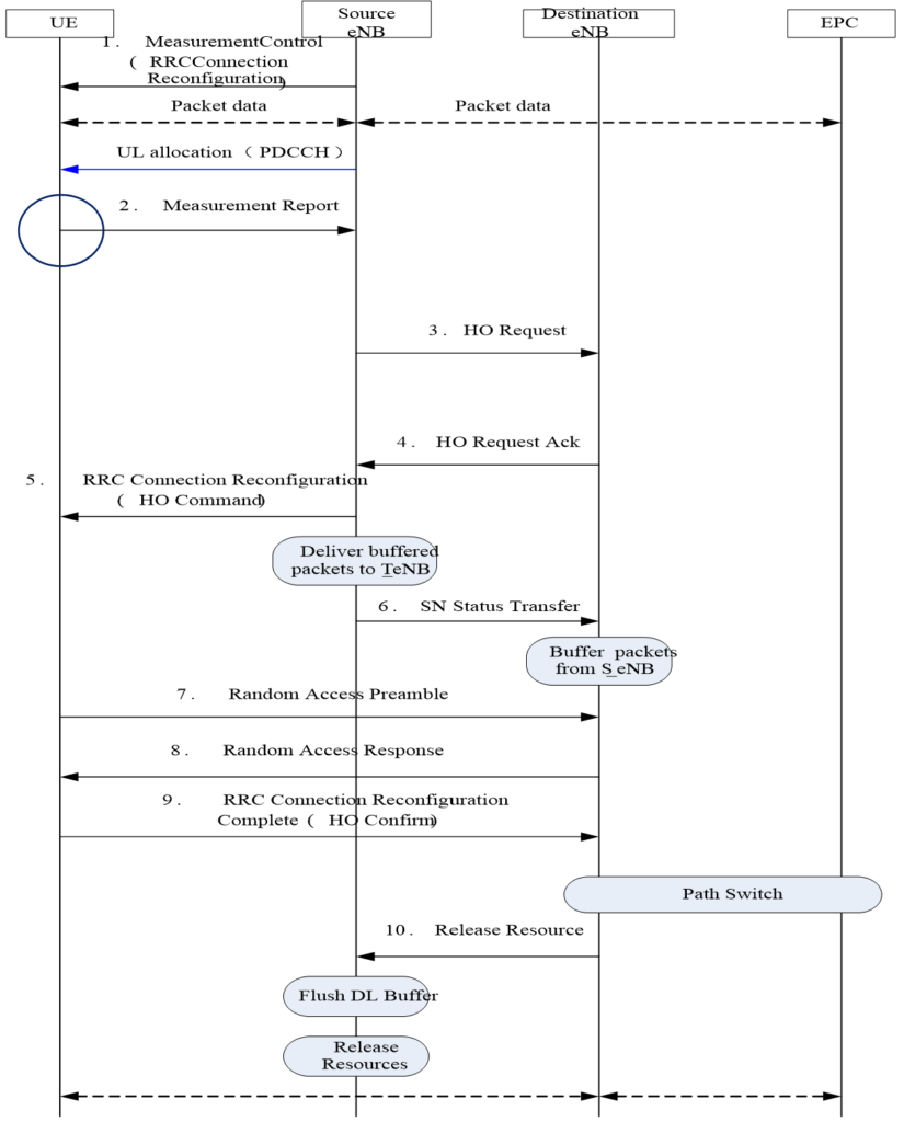
Step 1: Measurement Control.
Measure Control, generally carried in the reconfiguration message in the initial connection or last handover command.
Step 2: Measurement Report.
Measure Report, the UE reports the cells falling within the handover margin according to the measure control messages.
Step 3: HO Request.
At the receipt of the measurement report, the source eNB requests to the destination eNB for resources and configuration information. Please note that, interaction within the eNB is enough for handover within an eNB. For handover between eNodeBs, X2 or S1 interface should be used, with X2 preferred.
Step 4: HO Request Ack.
The destination eNB feeds the acknowledgement message and other configuration information back to the source eNB.
Step 5: RRC Connection Reconfiguration.
The source eNB sends the acknowledgement message of the destination eNB and reconfiguration message which contains the measurement control of the destination eNB to the UE, and notify the UE that the destination eNB is ready for connection.
Step 6: SN Status Transfer.
The Source eNB delivers the buffered packets of the UE service to the destination eNB.
Step 7: Random Access Preamble.
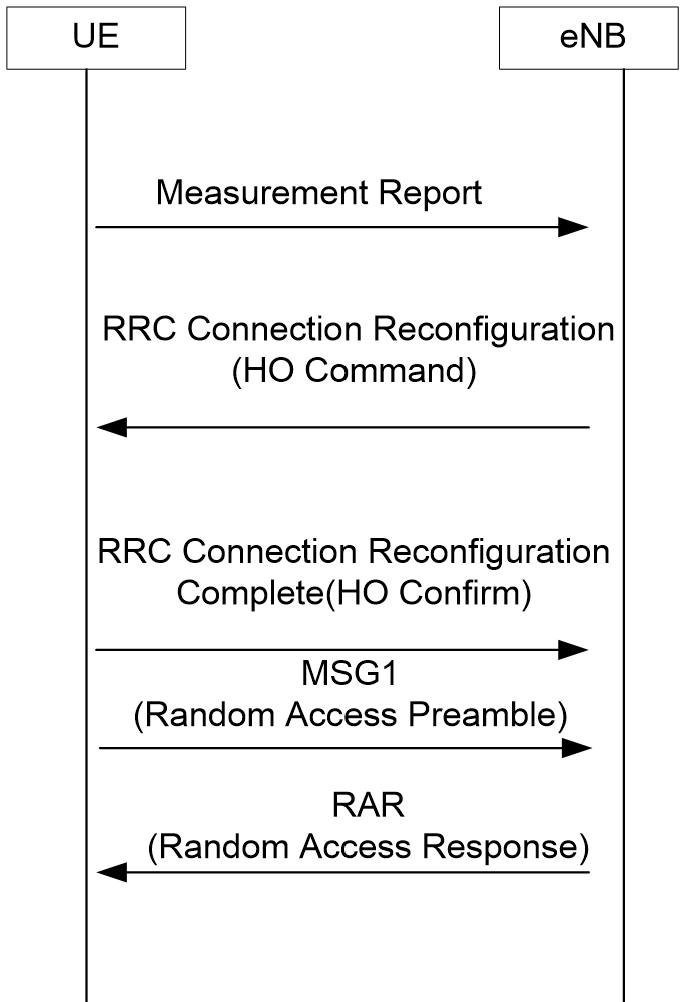
Upon the receipt of the reconfiguration message in step 5 (handover command), the UE uses the access information in the reconfiguration information to connect.
Step 8: Random Access Response.
The destination eNB access response, with this command received, it is deemed as access completed. Then the UE sends the reconfiguration complete message on RRC layer (step 9).
Step 9: RRC Connect Reconfiguration Complete (HO Confirm).
The UE Reports the reconfirmation complete message to the destination eNB, now the handover process is complete.
Step 10: Release Resource.
When the UE connected successfully, the destination eNB notifies the source eNB to delete the context information (flush DL buffer) on the UE.
Classification of Handover.
Based on the actual application situations, handover can be done within one eNB, over the X2 interface or the S1 interface. The section below introduces these handover modes separately. All of the handover methods below are introduced given that the UE is already connected and measurement configuration is acquired.
1. Handover Within an eNB.
The Handover within an eNB is relatively simple. Since the handover source and destination are in a same eNB, then it is determined just inside the eNB and does not have to request to EPC for data path switch.

2. Handover over the X2 Interface.
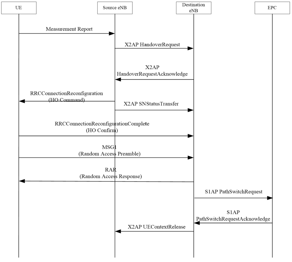
This is used for establishing handover between neighbor cells that are connected with the X2 interface. Upon receiving the measurement report, the source eNB delivers handover request to the destination eNB through the X2 interface (step 3 in Figure 1‑1), sends handover command to the UE after getting the acknowledgement of the destination eNB (step 4 in Figure 1‑1) and meanwhile it sends SNStatus Transfer the message which contains the data packet buffer and buffer number and other information to destination eNB. After the UE connected to the destination eNB, the destination eNB will send path switch request to EPC with the purpose of notifying the EPC to transfer the UE service to the destination eNB. X2 handover is in preference to S1 handover.
Get More details about LTE X2 Handover.

3. Handover over the S1 Interface.
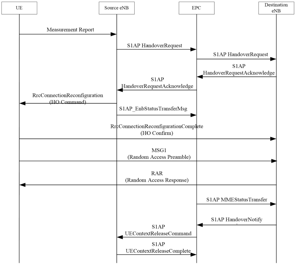
The handover over the S1 interface takes places between neighbor cells when there is not X2 and not in the case of handover inside an eNB. The basic flow is identical to that of the X2 handover, with the only difference that all interactive signaling are transferred over the S2 interface in EPC, which has a slight longer delay than the X2 handover.

Get more details about S1 Handover in LTE.