This method statement will serve as a minimum guideline to carry out the Cathodic Protection Installation. Main keywords for this article are Cathodic Protection Installation Method Statement, Sacrificial Anode installation, Reference Electrode Calibration, Cathodic Protection System Commissioning.
Cathodic Protection Installation Method Statement
Work Execution Procedure
Installation of Anodes (Impressed Current or Sacrificial) for Underground Pipe
- Cathodic Protection materials shall be withdrawn and handled carefully when loading and unloading on the transport vehicle.
- Study latest issued approved for construction drawings and details. Consider priority areas for construction with respect to milestone schedule.
- Anodes shall be installed in place based on the latest issued approved for construction drawing and with approved vendor recommendation together with their approved manual installation procedures and/or brochure.
- Anode ground bed area should have been prepared and ready for anode assembly installation. Soil sample for each anode bed shall require Earth Resistance Testing. Thermal sand bedding must be provided, and inspected by QC Inspector, shall be recorded.
- The method of applying cathodic protection to buried pipe work/structure using sacrificial anode, impressed current and/or combination of both shall be in detailed with latest issued approved for construction drawing and Cathodic Protection vendor’s manual. The extent of the protection system shall be shown in the drawing, and shall be normally limited to the onsite installation by means of insulating joints/flanges, physical segregation of electrical earthing system, polarization cells and the like. Precautionary measures shall be taken during installation to pipe works/structures to exclude as much as possible the unwanted extension of the protection system by inadvertent contact with metal sleeve, piling reinforcement and other extraneous buried steel work, which may result shielding or increase current drain.
- Survey the pipe route to determine accurately the anode and test box installation as shown on the construction drawings. Anodes will be installed in placed manually taking into consideration all necessary precaution to prevent material damages due to poor handling.
- Install anodes horizontally below pipe bottom elevation as specified in the AFC drawing. Otherwise, install it with a depth of 900mm minimum and offset from pipelines by minimum of 600mm, as per standard drawing . Should there be conflict with AFC drawing and/or this method statement, a request for inspection (RFI) shall be raised to resolve such issue.
- Route anode lead wire(s) to assigned positive junction box. Anode lead wire shall be routed close to pipe and laid below pipe bottom elevation in clean sand, free of sharp stones and other foreign objects that could cause mechanical damage.
For Sacrificial Anode Installation
A sacrificial anode is a device used in cathodic protection systems to protect metal structures from corrosion. It is a less noble metal that is intentionally installed and connected to the metal structure that needs protection. The sacrificial anode is designed to corrode preferentially instead of the protected metal, thus sacrificing itself to prevent the corrosion of the more important structure.
The principle behind sacrificial anodes is based on galvanic corrosion, which occurs when two dissimilar metals are in electrical contact in an electrolyte (such as soil, water, or concrete). In the presence of an electrolyte, a galvanic cell is formed, and one metal acts as an anode (where corrosion occurs) and the other metal acts as a cathode (where corrosion is prevented).
- Sacrificial anode shall be installed as per approved for construction drawing/ or Saudi Aramco Standard Drawing in accordance with vendor recommendation.
- Electrical connection between anode and pipe work/structure is normally to be made by bracing or exothermic (cad weld) welding. The attachment shall ensure a minimum of 1500mm spacing from the other weld if not specified in the drawing.
- Anode shall be provided with either steel inserts for mounting direct onto pipe work or insulated copper tails for remote installations.
- Sacrificial Anode shall be sprayed with water prior to back filling.
- Provide sufficient slack cables at each end of cable run to prevent stress to cable connections during backfilling of pipelines.
- QC inspection for anode installation shall be requested for inspection and result will be filed and recorded.
- Backfilling should be monitored to prevent possible vandalism or damage to CP cables.
INSTALLATION AND REFERENCE ELECTRODE CALIBRATION
A reference electrode is a crucial component in cathodic protection systems used to measure and monitor the effectiveness of corrosion protection measures. It provides a stable and known electrical potential against which the potential of the structure being protected can be measured. This allows for accurate evaluation of the corrosion status and the performance of the cathodic protection system.
- Cathodic Protection materials shall be withdrawn and handled carefully when loading and unloading on the transport vehicle.
- Study latest issued approved for construction drawings and details. Consider priority areas for construction with respect to milestone
- Anodes shall be installed in place based on the latest issued approved for construction drawing and with approved vendor recommendation together with their approved manual installation procedures and/or brochure.
- Calibrate reference electrodes in accordance with specific standard prior to installation. Quality Control Engineer shall witness the activity as required.
- Install the reference electrodes as per layout drawing and route the cables via the cable conduit entry to the temporary manhole located outside the ring wall.
- Install proper markers or identifications to cathodic protection conductors as per approved by company.
- Review carefully the installation detail provided ensuring that the reference electrodes are properly installed in accordance with design standards and specifications.
- Hazardous installation regarding cathodic materials shall be addressed to include material specifications and workmanship with precautionary measures shall be taken while connecting to power source.
- QC inspection and test for installation of monitoring tube and reference electrode shall be requested and result shall be filed and recorded on approved QC Forms.
Rectifier and Junciton Boxes
Rectifiers: A cathodic protection rectifier is an electrical device used to supply a direct current (DC) to the protected structure, such as pipelines, tanks, or other metallic assets, to counteract corrosion. It converts alternating current (AC) from the power source into the required DC output that drives the cathodic protection process. The primary function of the rectifier is to provide a controlled amount of current to the anode system, either sacrificial anodes or impressed current anodes, to generate the protective electrochemical reactions that mitigate corrosion.
Junction Boxes: Junction boxes are used in cathodic protection systems to provide a safe and organized enclosure for connecting various components of the system, including anodes, cables, reference electrodes, and bonding conductors. These boxes serve as distribution points where different cables are terminated and connected to each other or to the main power source.
- Cathodic Protection materials shall be withdrawn and handled carefully when loading and unloading on the transport vehicle.
- Study latest issued approved for construction drawings and details. Consider priority areas for construction with respect to milestone schedule.
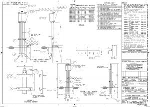
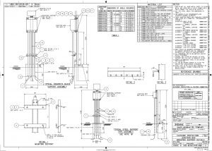
- The junction box shall be fixed in position. A foundation with mounting frame shall be prepared as per drawing following.
- Rectifier and Junction Boxes shall be installed in place based on the latest issued approved for construction drawing and with approved vendor recommendation together with their approved manual installation procedures and/or brochure.
- All rectifiers and junction boxes concrete foundation should have been completed and steel supports shall be fabricated and installed as per Standard Drawing and approved for fabrication drawing and procedures.
- Rectifiers and junction boxes shall be installed manually or by using lifting machine (if necessary based on the approved for construction drawing).
- The transformer and rectifier unit shall be installed in reference with SAES-X-400 Sec. 6.3.2.
- Alignment and stability of installed equipment shall be carefully checked.
- QC inspection for rectifier and junction box shall be done as per request for inspection and the result shall be filed and recorded on approved forms.

Cable Installation
- Cable materials will be visually inspected for possible manufacturer or handling damages and correctness of packaging based on specification before withdrawal and transporting to work site. Any sign of damages or discrepancies on document specification shall be reported immediately to Representative for disposition.
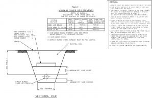
- Installation of direct buried electric cables in the plant shall be in accordance with standard drawings following.

- Cable laying work will be performed manually using cable reel stand and rollers, putting extra attention on cable route’s bends and sharp edges to eliminate the possibility of cable necking or damages.
- Cable tags must be installed at the lead end of the cable before the start of cable pulling and the other end of the cable after cable pulling.
- All system cables shall be routed in accordance with International / Saudi Aramco standard drawing BELOW and collected together at the appropriate junction box location.
- QC inspection shall be requested for power cable insulation test and loop check prior to backfilling of the trench. After inspection, cable ends will be tapped to protect and avoid moisture entry. All inspection results of power cable insulation test and loop checking shall be recorded on approved QC form.
- Installation of DC cables shall be as per International Standards or Saudi Aramco Best Practice SABP-X-003 Cathodic Protection Installation requirements section 4.2.4.

Cable Termination
- Cable gland (if required) should be checked against the actual cable size and cable schedule to ensure proper fitness and usage to which it conforms to area classifications.
- Cable glanding shall be performed by competent and qualified industrial electrician under the supervision of his foreman.
- Unarmored cables should be dressed properly, neat, and safely manner inside the equipment termination panel, taking extra attention not to damage the cable insulation while performing the termination works.
- Correct size of terminal lug and crimping tool dies should be used.
- Lead wire connection to the rectifier must be mechanically secure and electrically conductive. Proper terminal lugs must be used, saying right materials for the right job.
- Visual inspection will be conducted on the completed termination work to be witness by concerned DEC/JGC representative.
- Before the power source is energized it must be verified that the negative lead is connected to the anodes.
Cable Bonding
- Bonding of cathodic protection cables to underground pipes shall be by exothermic process and should conform based on the requirements of International Standard Drawing, Cathodic Specifications, Cathodic Protection Vendor manual and installation assembly provided.
- Pipe and cable for bonding should be clean, dry and free from any oil or grease.
- Strip the cable end insulation just enough to match the cad weld mold. Check mold tag and cartridge for proper size and type of use suitable to the pipe material to be welded, using manufacturer’s recommendation.
- Clean area of pipe approximately 50x50mm for each cad weld connection. Wire brush and file this area to obtain a clean surface.
- Thermite bonding shall be performed by a competent industrial electrician under close supervision of his foreman. Safety requirements shall be addressed and followed all throughout the activity.
- Test strength of weld connection by lightly tapping top of weld with a one-pound hammer.
- Remove all weld slag and spatter, sharp edges and burrs with a metal file or wire brush.
- All bonding point shall be coated with bitumen paint and let dry before filling all void areas with seal patty.
- All bonding point shall be Holiday tested (refer to SAES-X-400 Sec 6.4 sub Sec. 6.4.3) and inspected by the concerned QC inspector prior to the backfilling of the pipe.
- After above ground piping connection to underground pipeline a Leakage/ Isolation Test will be performed on all insulating flanges. All test result shall be recorded on approved incorporate form provided and file for future reference.
CABLE SPLICING
- Underground connecting splices of the cathodic protection cables to the ground installation shall be avoided whenever possible.
- Extension cable whenever required and shall be of the same type, size, and color as the cable being extended.
- Alternative cables during short term supply limitations shall be of larger size and the insulation color can be match with heat shrink extending from junction box terminal to at least 300mm beyond any conduits and into direct burial.
- Locate the cables to its final position and make it straight as possible. Only the minimum length of extension cable required shall be added.
- Square cut the cable ends and remove sharp points. The conductor to conductor joints shall be made by appropriate crimping tool and butt-connector.
- All splices shall be carefully checked prior to backfilling ensuring that sufficient slack are left to avoid strain on the cables.
- If in case a short cable requires extension, splicing shall be made by using splicing kit and to be performed by qualified splicer/terminator.
- QC inspection shall be requested for all completed underground cable splices. Inspection results shall be properly recorded and file for reference.
Cathodic Protection System Commissioning
- The pipe to soil native potential (i.e. the potential before the transformer rectifier is switched on) shall be measured at each test station and recorded on form. A portable reference electrode shall be placed in contact with the soil as close as possible to the pipe under test. The soil should be pre-wetted at this location to ensure good electrical contact. The digital multi-meter should be switched to “DC volts”. As suitable scale shall be selected (commonly 2V DC). The negative terminal of the DVM should be connected to the portable reference electrode cable and the positive terminal should be connected to a test lead connected to the structure negative terminal inside the test station. The resulting reading of voltage will be pipe-to-soil potential.
- Any rheostat inside positive distribution boxes, anode junction boxes or positive and negative junction boxes shall initially be set to minimum resistance.
- The TR (transformer rectifier) shall be switched on using the breaker. Initial tap setting of the TR shall be course 1, medium 1 and fine 1 (there are four course, four medium and four fine adjustments. A total of 64 increments are therefore available). The correct polarity shall be confirmed by measuring a negative shift in potential at any convenient test station. If the polarity is incorrect (i.e. if there is a positive shift in potential) the unit shall be switched off and the system reconnected insuring correct polarity.
- The total output current and voltage shall be determined by reading the TR meters and checked using a portable meter. The current is calculated by multiplying the voltage across the shunt within the TR by the appropriate conversion of factor. The current shall be adjusted (using the tap settings) to approximately 25% of the design current.
- The distribution of current shall be checked on the positive and negative sides of the circuit by measurement across the appropriate shunt in the anode junction boxes and negative junction boxes. All results shall be recorded on form.
- The system shall be left to operate as set for 24 hrs.
- On potentials shall be measured at all test stations. All results shall be recorded on the form.
- The level of protection shall be assessed form the values of ON potentials. If any values are less than –1,000 mV (vs. Cu/CuSO4) then the system shall be adjusted to achieve at least –1,000 mV at all locations whilst minimizing the number of locations where –3,000mV is exceeded. If all potentials are between –1,000 mV and -3,000 mV the system will not require any adjustment and commissioning shall be recorded as complete.
- If adjustments are required the system shall be left to operate for a minimum of 24 hrs at the new settings before re-testing.
Following all commissioning reports of cathodic protection.