1.0 PURPOSE
2.0 SCOPE
3.0 REFERENCES
4.0 RESPONSIBILITIES
5.0 WORK SEQUENCE / PROCEDURE
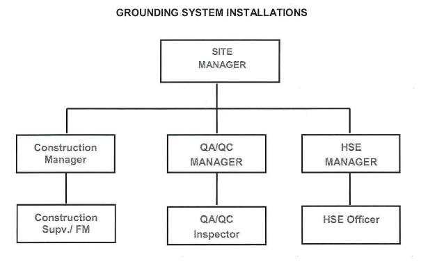
6.0 ORGANIZATIONAL CHART
7.0 INSPECTION &QUALITY RECORDS
8.0 SAFETY PRECAUTIONS
9.0 ATTACHMENT.
GROUNDING INSTALLATION & TESTING METHOD STATEMENT
1.0 PURPOSE
To ensure that Grounding system installation is performed safely, efficiently and in accordance with good working practice, as per Saudi Aramco Job Specifications. The procedure is intended to provide general application guidance and establish controls during preparation and installation.
2.0 SCOPE
This Method Statement is applicable to all grounding system installation and testing activities which are to be installed on the Naphtha Project at JAZAN REFINERY & TERMINAL PROJECT- Package 12.
3.0 REFERENCES
SAES-P-111 : Grounding
SAES-P-104 : Wiring Methods and Materials
SAES-A-114 : Excavation and Backfill
IEEE 80 : Guide for Safety in Alternating Current Substation Grounding
IEEE 81: Guide for Measuring Earth Resistivity, Ground Impedance and Earth Surface Potentials of a Ground System
IEEE 142 : Recommended Practice for Grounding of Industrial and Commercial Power System
NFPA : NFPA 70
NEC: National Electric Code
PQAM/QCIP : Project Quality Assurance Manual/Quality Control Inspection Plan
SATIP-P-111 -01 : Grounding and Bonding
SAES-J-902 : Electrical System for Instrumentation
UL 467 : Grounding and Bonding Equipment
4.0 RESPONSIBILITIES
4.1 Site Manager
Site Manager has responsible for supporting and encouraging the related staffs and
workers, to ensure that the project is completed on time and within budget, that the
project’s objectives are met, so as for them to participate actively as worksite.
4.2 Construction Manager
Responsible for the overall implementation and execution of Electrical Installation works.
4.3 QA/QC Manager
Responsible for the overall discipline of QA/QC Inspection, verification of the project
specification, documentation and QC records for final acceptance.
4.4 HSE Manager
Responsible for Safety implementation and ensuring all safety requirements ha ve been
implemented within the construction areas as per Saudi Aramco safety procedures and
management.
4.5 Electrical Supervisor
Ensure relevant permits are raised and received prior to commencement of work, with full
compliance by all associated craftsmen to the requirements of this procedure, Quality
Control Procedures, reference drawings, and Customer’s Specifications for the grounding
installation work.
4.6 Electrical Foreman
Ensure relevant permits are raised and received prio r to commencement of work, with full compliance by all associated craftsmen to the requirements of this procedure. Responsible for the execution of the work, manpower assignments and hourly monitor the work done and preparing the work activities for the electrician.
4.7 Quality Control Supervisor
Ensure the relevant works done are thoroughly checked daily and corrected according to Standard, IFC drawing and the project specifications and by all associated craftsmen to the requirements of this procedure.
4.8 Quality Control Inspector
Monitor daily, electrical activities and verify compliance to Customer’s Specifications. Perform activities in accordance with the Project QA Manual and Quality Control Inspection Plan. Prepare daily QC records and final acceptance documentation. Maintain a close working relationship with the Customer’s Representative.
4.9 Safety Supervisor
Monitor that all safety requirements have been adequately addressed and the work is
carried out in accordance with Aramco project safety procedures.
5.0 WORK SEQUENCE I PROCEDURE
5.1 Required Tools and Equipment
– Hydraulic Crimping Tool
– Thermite Weld & Accessories
– Cable Cutter
– Forklift
– Bobcat
– Skid Loader
– Stakebed Truck
– Bore hole drilling machine
– Ladders & Scaffolds
– Cable Stripper
– Splicing Knife
– Electrical Pliers
– Ground Tester
– Cadweld Powder (Weld Meta l)
– Exothermic Mold
– Mold Holder
– File diff. size
– Cable Cleaning Wire Brush
– Mould Cleaner
– Flint Gun
– Ground Rod Clamp
– Grounding Pit
– Ground Rod Coupling & Driving Stud
– U-Bolt Ground Clamp
– Other Relevant Tools
5.2 Pre-installation Activities
5.2.1 Ensure that all relevant documents have been approved by Saudi Aramco prior to commencing installation, and that the latest revisions of IFC drawings, specifications including approved procedures are disseminated to concerned personnel who will carry out the work.
5.2.2 Obtain/ensure the work permits are in place before/prior to start a job.
5.2.3 Ensure that all grounding rods, cables, connectors and other miscellaneous materials are available, to be transported from warehouse I laydown area to the work area and complies with the project specifications.
5.2.4 Ensure that all material requirements shall be as required in SAES-P-111 paragraph 5.
5.2.5 Check that all electrical materials shall be clean new and unused.
5.2.6 Check the manufacturer’s name, trade name or other acceptable marking whereby the organization responsible for the product ca n be readily identified.
5.2.7 Check the availability of the product installation instruction.
5.2.8 Check that the materials shall be traceable from the manufacturer and supplier through delivery, storage, fabrication, erection, installation, repair modifications and used.
5.2.9 Electrical materials shall be identified by using tags, stamps, color coding, stencils or labels. All the materials are check in the presence of QC with proper communication.
5.2.1 0 Check materials for damage before transporting to the work area. All materials of doubtful condition or quality shall be immediately segregated from the job site. An NCR must be raised and the material shall not be used .
5.2.1 1 Over hanging from the trailer I truck body of any material is not allowed. Ensure that they are properly and adequately secured and supported.
5.2.12 Secure work pe rmit for grounding system installation and other associated works, if required.
5.2. 13 Ensure Safety Barriers are erected at designated work areas.
5.2.14 Check and confirm actual proposed routing against approved construction drawings.
5.2.15 For aboveground installation, ensure adequate scaffold ladders and access ways are available at the work location.
5.2. 16 Ensure that grounding rods , cables, connectors and accessories needed to complete the work are available at designated areas scheduled for installation.
5.3 1nstallation Activities
5.3.1 Grounding
• Install grounding system cables, rods and accessories as depicted on IFC drawings. Install pr9ducts in accordance with manufacturer’s instruction, approved drawings and Job Specifications, including Saudi Aramco Electrical Installation drawings.
• Excavation and backfill shall be carried out in accordance with SAES-A-114.
• Verify that final backfill and compaction has been completed before driving any rod electrodes into the ground.
• Install grounding electrodes at locations indicated on IFC drawings and job specifications. Ground wells shall be installed and equipped with removable covers for maintenance access to the ground rods and their mechanical connections.
• All surfaces for grounding connections shall be thoroughly cleaned before the connection s are made.
• Following completion of installation , submit “Request For Inspection” (RF I) to site QC Section, indicating scheduled time I date for inspection.
5.3.2 Underground Grounding Installation
• Check and confirm the actual underground grounding routing for installation against approved construction drawings.
• Layout the grounding grid cable trench by marking using white .pulverized powder the areas to be excavated.
• Excavation work shall be in accordance with SAES-A-114.
• Excavation shall be performed as required by the design drawings, to the dimensions, grades, and elevation as noted and required .
• All buried grounding conductor shall be in stalled at a minimum of 460mm below grade.
• Underground grounding cable connection shall be performed using exothermic connection.
• Ground cables crossing access way shall be run in duct banks or PVC conduits.
• Buried grounding cables shall have clearance of 300mm (minimum) from any underground obstruction.
• Where there are earth connections between feeders & branches are located in the cable trench, ensure that joints have been connected and tapped before backfilling.
5.3.3 Above Grounding Installation
• Check and confirm the aboveground grounding routing for installation against approved construction drawings.
• All Earthing points to be checked as per the drawing.
• Earth wire leaving the ground (stub-up) shall be protected by PVC conduits or RGS conduit.
• Sealing for stub-up PVC conduit or RGS conduit.
• The end(s) of ducts and conduit terminating below or in open air shall be sealed with duct sealing putty or an equivalent compound.
• All above ground cable connections shall be compression type.
• All cable Trays are to be bonded together and to the main ground grid with a 70mm² green PVC insu lated copper ground conductor at interval not exceeding 25 meters apart.
• Frames of Medium Voltage motors shall have at least two (2) ground connections.
• Ensure a complete As-Built record of grounding installation is maintained for above and below ground (Red line I Mark-Up).
5.3.4 Grounding Rod Installation
• Ground Rod shall have the following characteristic:
a. Bare copper or copper jacketed steel or galvanized steel.
b. Have a minimum length of 2.4 meters. Jointed rods are permitted but each joint must be at least 2.4 meter long.
c. For copper or copper jacketed steel rods be minimum of 16 mm in diameter and for galvanized steel rods be a minimum of 19 mm diameter.
d. Install the grounding rod and accessories as depicted on the IFC drawing.
e. Excavation and backfill shall be carried out in accordance with SAES-A-114.
f. Verify the final backfill and compaction has been completed before driving the ground rod.
g. Having confirm the soil final backfill and compaction, in stall the ground rod by driving using a light hammer, or mechanical, pneumatic or gasoline powered ground rod drivers.
h. Continue driving until the desired depth is obtained .
i. Below ground connection to the grounding grid or ground rod or between conductors and or grounding rods shall be made using one of the following methods:
~ By thermite welding or brazing
~ By approved compression grounding connectors.
~ For connection at ground test station only where it is necessary to disconnect ground conductors for tests, approved mechanical connectors may be used.
• When using Thermite weld / Cad weld, the following step shall be performed:
a. Prior to making a connection, the detailed instruction and safety precautions provided by the manufacturer should be read properly.
b. Sub-contractor will conduct training for skilled manpower to do thermite weld and cad weld .
c. Clean the upper tip of ground rod and the conductor with approved cleaning solvent.
d. Place the grounding rod and cable mould and close handle to lock mould.
e. Drop metal disk and weld metal into the mould.
f. Sprinkle starting material over weld metal and on lip mould.
g. Close cover and ignite.
h. Open cover after weld metal solidifies.
i. Inspect weld per manufacturer’s recommendation. Coat weld with bituminous paint and adhesive PVC insulation tape.
j. Prior to priming exposed area, clea n substrate to bright metal.
k. Thermite weld connection is not recommended in areas where a hazardous fire atmosphere may exist during the attachment process.
5.3.5 Grounding Bus Bar Installation
• Install grounding bus bar and accessories as depicted on IFC drawings.
• Install products in accordance with manufacturer’s instruction, approved drawings and specifications.
• Ground Buses in Switchgear, Switchboard, and MCC shall have two connections to main grounding electrode / grid.
• Grounding plate I bus bar fixed on concrete shall be installed using a pre arrange anchor screw on masonry concrete wall at elevation as per drawing and standard.
• Grounding plate I bus bar fixed on metallic structures shall be installed using head bolts welded on flat surface of metallic structure at elevation as per drawing and standard.
5.3.6 Grounding Installation System Requirements
• Substation Grounding
a. All electrical equipment in the substation, substation yard , and within 5 meters of the substation fence shall be connected to the grid or to a ground bus connected to the grid.
b. Substation ground grids shall be constructed of minimum 70mm2 (2/0 AWG) stranded bare copper cable. If used for grid conductors in substation for potential control purposes be bare and if used in soils less than 70 ohm-meters resistivity be tinned.
c. For a substations having equipment operating at a nominal system voltage exceeding 1000 volts, a ground grid meeting the requirements of IEEE 80 for step and touch potential shall be installed.
d. The three phase electrical system shall be grounded at the neutral point of the wye-connected windings of the transformer or generators and connected as directly as possible to th e grid or grounding electrode.
• System Grounding & Grounding Electrode
a. The system grounding connection shall be made directly to the grounding electrode and be routed separately from the equipment grounding connections.
b. The ground resistance of made electrodes (ground rod I or ground grid) used for system grounding shall not exceed 1 ohm for solidly grounded system above 600V, 5 ohms for re sistance grounded systems above 600V and 5 ohms for a system under 600V.
c. All grounding electrodes used for the system in plants, bulk distribution facilities shall be interconnected to form a single ground system.
d. The grounding electrode used for system grounding (including separately derive systems) for each of the facility or plant shall have a minimum of two connections to the ground grid or ground loop use d in the area.
e. The requirement ca n be met by connections to the grounding electrode of the substation(s) which supply the area.
• Equipment Grounding
a. Conduit, Cable Tray, or Cable Armour, shall not be relied as the equipment grounding conductor and a bare or insulated copper conductor shall be installed in the same conduit, cable tray, cable , or cord or shall otherwise accompany the power conductors.
b. Installation must meet NEC bonding and grounding requirements for such use. In hazardous location equipment grounding conductors run in a conduit or cable tray shall be insulated or enclosed within the jacket of a multi -conductor cable.
c. Aluminium & Stainless Cable Trays containing only circuits operated at, or below, 50V to ground may be used as equipment grounding conductors provided NEC requirements for such used are met.
d. The common conductor shall size in accordance with NEC Table 250-122 for the largest power conductor in the tray, with a minimum size of 25mm2 (#4AWG).
e. Connection shall be made between this common grounding conductor and other grounding conductors for intersecting or branch trays, and to extend the equipment grounding conductor beyond the tray.
f. This common conductor shall be bonded to each section of the cable tray system with a connector approved for a copper to aluminium connection.
g. Shields and armour of power cable shall be grounded at both ends. Continuity at splices shall be maintained by bonding across the splice.
h. Metallic conduit sha ll be grounded at both ends point by bonding to a grounding conductor, a grounded metal enclosure, or to a grounded metal cable tray.
i. Ground busses in the switchgear, switchboards, and motor control center shall have two connections to the main ground electrode.
j. Raised computer floor shall be grounded by bonding a minimum of two pedestals at opposite corners to the nearest ground bus or grounding electrode.
k. Structural steel supports for process equipment and piping and structural steel column for buildings, grounding connections shall be made at least every 25m with a minimum of two connections at opposite corners of its structure building.
I. Frames of equipment (motors, generators and transformers) operating at 1000 V or greater shall have two connections to a supplementary electrode.
m. Motors, transformers, and generators operating at nominal voltage of 480V shall have a minimum of one connection to a supplementary grounding electrode.
n. Metallic enclosures for panel boards, circuit breakers, switches, fuses, motor controllers, switchgears, switch racks, motor control center, motors and transformers, metal vessels, stacks, exchangers, loading and unloading facilities and the likes when not bolted to a grounded structural steel shall be connected to a supplementary grounding electrode.
o. Manually operated switches for overhead power lines shall have operating platforms and be grounded as shown on a standard drawing AA-036572.
p. Underground ground conductors shall be insulated when within 3 meters of buried metal pipeline or metal piping.
q. Underground ground conductors electrically connected to buried pipe lines, buried metal vessels, or metal tanks sitting on grade shall be insulated. The associated ground rod shall be galvanized steel if the area is subject to cathodic protection.
r. Grounding conductors extending through concrete or asphalt shall be run in PVC conduit (preferred) or PVC coated rigid steel conduit. Grounding conductors in steel conduit shall be bonded.
s. Grounding conductors which do not accompany associated power conductors in the same conduit shall not be installed in metallic conduit except where PVC conduit is not suitable and it is necessary to protect the conductor from mechanical damage.
• Fence Grounding
a) Electrical substation fence sha ll be grounded as follows:
• Substation fences shall not be PVC coated and shall be grounded in a minimum of two locations to the local ground grid or loop.
• All fences for substations containing equipment fed from solidly grounded system operating at above 1 OOOV line to line shall be bonded to a grounding conductor buried approximately 1m outside the fence and paralle l to the fence.
• A second conductor shall be buried 1m inside fence if the substation ground grid does not extend into this area.
• The grounding conductor(s) shall be connected to the substation ground grid at a minimum at four locations spaced equally around the loop.
• The fence shall be shall be connected to the grounding conductors at interval not exceeding 15m.
• Corner posts and gate posts shall be connected to the grounding conductors. Gates shall be bonded to the gateposts with connectors.
5.4 Termination and Torqueing
5.4.1 Grounding conductors shall be soft drawn copper.
5.4.2 Buried grounding conductor shall be annealed bare tinned copper.
5.4.3 All compression connector shall be tinned copper.
5.4.4 Compression (crimped) type connectors shall be used for splicing and terminating stranded conductors.
5.4.5 Compression terminal connectors for 4/0 and larger conductors shall have two holes NEMA design.
5.4.6 All fasteners (i.e., nuts, bolts, washers, etc.) used to connect and assemble the grounding connection system shall be 316 SS.
5.4.7 In severe corrosive environments, 316 SS fastener shall be used.
5.4.8 Neutral (grounded) conductors shall be identified by colour white or grey, and insulated grounding conductors by co lour green or green with yellow stripes.
5.4.9 Torqueing shall be done for grounding connection.
5.4.1 0 Graduated Torque Wrench shall have valid Calibration Certificates.
5.4.11 Torque values should be in accordance with Saudi Aramco Test Report (SATR-P-3706) Attachment 1-NETA 1999 Tab le 10.12 (See attached)
5.5 Testing Procedures
5.5.1 Grounding- GES- Electrode Resistance Test (SATR-P-3702)
6.0 ORGANIZATIONAL CHART
7.0 INSPECTION & QUALITY RECORDS
~ All stages of work shall be inspected in accordance with the Approved Project Quality Control Inspection Plan.
~ Inspection / Quality activities shall be as per the corresponding SATIP and SAIC. (SATIP-P-111-01 , SAIC-P-3701 , SAIC-P-3705, SAIC-P-3708, SAIC-P-3709, SAIC-P3711, & SAIC-P-3018). (See attachment)
~ All the test and inspections shall be recorded and documented properly. (SATR-P3206,
SATR-P-3706,
SATR-P-3209,
SATR-P-3704,
SATR-P-3702.
8.0 SAFETY PRECAUTIONS
8.1 Barricade the working area.
8.2 All safety precautionary signboards must be visibly posted.
8.3 Wear full body harness when working at heights.
8.4 Ensure that only authorized personnel are within the affected area.
8.5 Maintained JSA at worksite by work Supervisor, requirements shall be discussed in daily TBT. (See attachment)
8.6 Complete WERA prior to commencing work.
8.7 Leather gloves to be worn during hot works.
8.8 Safety of personnel shall be of the outmost priority in the execution of work. So, ensure proper PPE compliance. (See attachment)
9.0 ATTACHMENT
~ Risk Assessment- Grounding Works
~ NETA 1999 Table 10.12