1.0 PURPOSE
The purpose of this Method Statement is to define the general sequence of events, interfaces and responsibilities relating to Cable Tray for the commercial buildings, plants and refineries.
2.0 SCOPE
The scope of this Method Statement covers the objective and requirement of steps to be followed applicable to Cable Tray for commercial buildings, plants and refineries.
METHOD STATEMENT FOR ELECTRICAL CABLE TRAY INSTALLATION
4.0 REFERENCE
4.1 Project Specification and Standards
4.1.1 Typical Installation of Cable Tray Work- J95-P-VA-529583-001 – 004.
4.2 ARAMCO Specification and Standards.
4.2.1 SAEP-302 Instruction for Obtaining a Waiver of a Mandatory Saudi ARAMCO Engineering Requirements.
4.2.2 SAES-H-1 01 Approved Protective Coating Systems.
4.2.3 SAES-P-100 Basic Power System Design Criteria.
4.2.4 SAES-P-104 Wiring Methods and Materials.
4.2.5 SAES-P-111 Grounding.
4.2.6 SAES-J-902 Electrical System for Instrumentation.
4.2.7 SAES-B-068 Electrical Area Classification.
4.2.8 Schedule Q Saudi Aramco Project Quality Requirements.
4.2.9 Schedule G Material, Tool s and Equipment.
4.2.1 0 Schedule D Safety, Health and Environmental Req uirements
4.2.11 Related Vendors In stallati on and Maintenance Manual and/o r Specification
4.3 International Standard
4.3.1 NFPA 70 National Electrical Code (NEC)
4.3.2 NEMA VE2 Cable Tray Installation Guidelines
4.3.3 NEMA VE1 Metal Cable Tray Systems
4.3.4 IEC 60840 International Standard
4.3.5 SATIP-P-1 04-03 Cable Tray Fittings and Accessories
4.3.5 Latest Revision of the following Documents shall be used
• Vendor Drawing
• Latest Approved Drawing
4.3.6 SAUDI ARAMCO Safety, Health and Environmental Standard
5.0 RESPONSIBILITIES
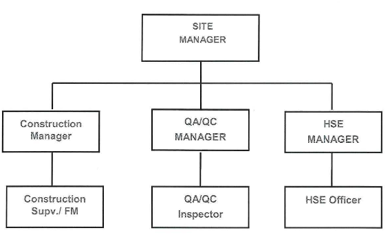
5.1 Site Manager
Site Manager has responsible for supporting and encouraging the related staffs and workers, to ensure that the project is completed on time and within budget, that the project’s objectives are met, so as for them to participate actively as worksite.
5.2 Construction Manager
Construction Manager has the responsibility for compliance with this Method Statement and shall ensure to review contract documents and provide all resources necessary to effectively implement throughout the construction period. Construction Manager shall monitor the quality and progress of the work and ensure that job target is achieved.
5.3 Electrical Supervisor
The Electrical Supervisor shall be responsible for construction work supervision, and ensuring that work is completed in conformity with drawings and specifications.
5.4 QA/QC Manager
QAJQC Manager has the overall responsibility for all QA/QC activities of the project. He shall be interacting with Electrical Site Manager related to all QAJQC activities. He shall be responsible for Nonconformance Management and Quality Audit.
5.5 QA/QC Inspectors
QAJQC Inspectors shall be responsible for Site QAJQC activities, in co-ordination with HSE team for Cable Tray works and inspection activities at site.
5.6 HSE Manager
HSE Manager shall monitor related works under carrying out, and advise supervisors’ for corrective measures, if required . He shall ensure holding of pre task HSE meeting / daily tool box talks covering details of specific tasks and specific job risks involved to the work force involved. He shall also ensure appropriate mode of communication in case of emergency.
6.0 ORGANIZATIONAL CHART:
ELECTRICAL CABLE TRAY INSTALLATION
7.0 CONSTRUCTION METHOD
7.1 Handling and Storage
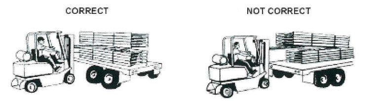
7.1.1 Cable tray loading and unloading methods are by hand , forklift, boom truck and crane (with the use sling). If hand loaded I unloaded, appropriate Personal Protective Equipment should be worn.
7.1.2 To prevent damage to cable tray, never drag during loading I unloading.
7.1.3 Aluminium and stainless cable tray shall be stored outdoors in their laydown area . They shall be loosely stacked and ventilated to prevent storage stain. Small accessories shall be stored in boxes in the warehouse to prevent loss.
7.2 General Requirements
7.2.1 All cable trays and supports shall be installed as shown on approved design construction drawings and located to avoid interferences with other facilities. Interferences shall be notified to DEC/JGC for solution and final disposition.
7.2.2 All installation requirements and tolerances shall be in accordance with the technical specification, the latest designed construction drawings and the applicable documents.
7.3 This Method Statement is intended as a practical guide for proper installation of cable tray systems. However the spread of fittings, types, finishes and installation requirements is considerably large for inclusion in this Method Statement.
7.4 Competent and qualified persons familiar with standard electrical construction practices, electrical equipment, and safety of electrical wiring systems will perform the work hereunder described.
7.5 In order to install the cable tray supports, required elevation from the floor to the bottom of the cable tray will be found and a level line with a laser or a nylon string established.
7.6 Cable Tray Supports.
7. 6.1 Install necessary supports for cable tray as per installation detail. All permanent materials (including fabricated supports), consumables, construction area and resources shall be prepared and checked prior to installation works and shall be approved by the clients.
7.6. 2 Supports for cable tray shall provide enough strongly to overcome the loads associated with future cable additions or any other additional loads applied to the cable tray.
7.6.3 All field cut on galvanized steel supports shall be touched up with approved paint primer immediately or as manufacturer’s instruction.
7.6.4 Supports shall be provided to prevent stress on cables where they enter another raceway or enclosure from cable tray systems.
7.6 .4 Supports shall be provided to prevent stress on cables where they enter another raceway or enclosure from cable tray systems.
7.6.5 Location of supports for cable tray system shall be in accordance with the recommendations of NEMA VE2.
7.6.6 To make a hole on structural steel cable tray supports use a Drilling Machine or Hydraulic Punching Machine by a skilled manpower.
7.7 Straight Section Installation
7. 7.1 Straight Section Position Refer to NEMA VE 2-2013 Edition
• After the supports are in place, the installation work of the cable tray shall begin at any convenient place.
• To begin, place a straight section across two supports so that the ends of the section are not directly on the support. The support span shall not be greater than the straight section length or as recommended by the manufacturer, to ensure no more than one splice is located between supports.
• Place the next straight section across the next support, and attach it to the previous section with a pair of splice plates and hardware. Splice plates shall be placed on the outside of the cable tray, unless otherwise specified by the manufacturer, with the bolt heads on the inside of the cable tray
7.7.2 Splice Plates
As per SAES-P-104 section 9.5:
a) Splice plates Joints) shall not be located over support joints and shall be located between supports and quarter points.
b) No more than one splice shall be located between two adjacent supports.
Expansion Splice Plates
• It is important that thermal contraction and expansion be considered when installing cable tray systems. The length of the straight 20m or in minimum three length (3 x 6m) cable tray run and the temperature differential govern the number of expansion splice plates required. The manufacturer’s data sheets shall be observed at all times. (See Cable tray typical Drawing).
• The cable tray shall be anchored at the support nearest to its midpoint between the expansion splice plates and secured by expansion guides at all other support locations. The cable tray shall be permitted longitudinal movement in both directions from that fixed point.
• For changes in vertical direction not requiring a radius, vertical adjustable splice plates can be used. Supports shall be located within 600 mm each sides of vertical adjustable splice plates
• Position splice halves so that offsets adjust for material thickness and fasten with nut and bolt using hole.
• Attach to positioned cable tray sections which will set needed angle.
• Drill to complete hole.
• Insert and tighten all hardware.
• For run changes in horizontal direction not requiring a radius, horizontal adjustable splice plates shall be used. Supports shall be located within 600 mm of each side of horizontal adjustable splice plates.
• Connect inside connector (short piece) and position cab le tray sections to retangle.
• Position outside connector locating hinge at mid-point.
• Drill required holes and install and tighten all hardware.
• For metal cable tray, bonding jumpers are required for electrical continuity.
Offset Reducing Splice Plates
• For immediate width changes, use offset reducing splice plates. Supports shall be located within 600 mm of each side of offset reducing splice plates.
• Use an offset reducing splice plate with a standard splice plate to form an offset reduction.
• Use a pair of offset reducing splice plates to form a straight reduction.
Vertical Support Plates
• Use vertical support splice plates for additional support of extended vertical runs.
End Plates
• For dead-end closure indicating termination of cable tray run use end plates.
7.8 Field Modifications Base on NEMA VE 2, 2013 Edition
Due to field requirements there would be need to modify cable tray, as such the following activities might be required
7.8.1 Marking
Using a square that reaches across the width of the cab le tray, gauge off the edge of one
side rail and mark both flanges. Next, position the square down the side face of the tray and mark the web of the rail. Marking can be done with a scribe, marking pen, or a pencil. For the sake of appearance permanent markers shall be avoided .
7.8.2 Cutting
The cut can be made using a hand held hack saw, carbide tipped circular saw, hand-held band saw or hi gh speed grinder. It is important to achieve a square cut to ensure a good splice connection. Cable tray manufacturer’s offer jigs and other devices to aid in field cutting and these generally come supplied with the tray. They shall be used as recommended by the manufacturer. After cutting, smooth the cut edges to remove any burrs.
7.8.3 Drilling
Holes for splice plates shall be drilled in field-cut cable trays. The most common method of locating the hole position is to use a splice plate as a template. Drill jigs shall be made available. A short piece of side rail that is punched with the standard factory hole pattern can be bolted to the splice plate to serve as a stop that rests against the end of the field cut side rail. Clamp the splice plate to the rai l and drill through the splice plate holes and the side rail. The correct drill size is dependent on the hardware supplied with the cable tray. Match the holes that exist in the cable tray. After drilling, remove burrs.
7.8.4 Finish
Aluminium / Stainless cable tray after cutting and drilling, need to deburring or file.
7.9 Grounding and Bonding
Metal parts of the cable racks and trays shall be bonded and connected to the earthing grid, they shall be electrically continuous. Electrical continuity can be achieved by cable to steel structure through equipment fixing bolts, clamping, riveting or by welding. All conducting support structures shall be earthed at the foot of the support as shall all apparatus mounted on non-conducting support structures. For specific areas requiring bonding for electrical continuity the manufacturer’s instructions shall be followed.
7.10 Installation of Bonding Jumpers
a) Jumpers shall always be sized to meet project requirements and or the manufacturer’s instructions.
b) Place screw head on inside of cable tray, pu t jumper on outside of cable tray, add flat washer, and locknut, and tighten.
7.11 As per SAES-P-1 04 section 9.1
a) Cable tray installed outdoors shall have ventilated covers.
b) Flanged type covers shall be secured with stainless steel banding and fasteners, one band per /’2 m of cover length, with a minimum of six bands per cover.
c) Cable tray run vertically in outdoor areas shall have covers on both sides. (see typical drawing for Cable Tray)
7.12 Installing covers on outdoor cable tray systems, should they be required , proper attachment is required to protect covers on outdoor cable tray systems from the force of the wind. When specifying covers for a system make sure the material and finish is clearly stated to satisfy the installation need and environment. See NEMA VE 2-4.6.5
7.13 Cable tray systems shall not be used in hoist ways or where subject to severe physical damage as per NEC 392.12
7.14 Cable trays shall be installed as a complete system. Field bends or modifications shall be so made that the electrical continuity of the cable tray system and support for the cables is maintained as per NEC 392.18(A)
7.15 Cable tray systems shall be permitted to have mechanically discontinuous segments between cable tray run s or between cable tray runs and equipment as per NEC 392.18(A)
7.16 Sufficient space shall be provided and maintained about cable trays to permit adequate access for installing and maintaining the cables as per NEC 392 .1 8(F).
7.17 As per SAES-P-119 section 6.3 Cable Trays in Substation building shall be installed as follows:
a) Parallel and right angles to the building walls.
b) Minimum of 200mm of vertical clearance shall be provided between cable trays.
c) The elevation of the bottom of the lowest interior cable tray shall be a minimum of 2.67 m above the main substation floor.
7.18 Cable tray system shall be installed accessi ble. If possible 300mm (12 inches) minimum should be left above or between installed systems to allow for cable installation and maintenance as per NEMA VE 2-4.
8.0 INSPECTION AND TEST PLAN
8.1 Refer to SATIP-P-1 04-03 for Cable Tray Installation.
9.0 INSTALLATION TOOLS AND EQUI PMENT
9.1 Equipment
• Cargo truck
• Crane and Lifting gear.
9.2 Tools
• Drilling machine
• Cutting disks
• Electrical hand tools
• Battery impact drill machine
• Hydraulic punching machine
• Tool case
• Electrical saw
• Set of socket wrench
• Hand grinder or Electric saw
• Hammer
• Set of Ratchet
• Electric drill
• Spanners different sizes
• Welding machine
• Plug, outlet etc .
• Torque Wrench
• Pipe wrench
• Cable tray and accessories
10.0 SAFETY PRECAUTIONS
10. 1 Ensure Safety Barriers are erected at designated work areas.
10.2 Ensures adequate scaffold ladders & access ways are available at the work location.
10.3 All safety precautionary signboards must be visibly posted .
10.4 Ensure that only authorized personnel are within the affected area.
10.5 The work shall be executed in accordance with the approved Total Safety Task Instruction (TSTI).
10.6 Maintained TSTI at worksite by work Supervisor, requ irements shall be discussed in daily TBT. (See attachment)
10.7Complete WERA (Work Execution Risk Analysis) prior to commencing work.
10.8 Respiratory protection if needed must be NIOSH approved and appropriate for HAZARD and to be maintained cleaned and stored properly.
10.9 All electrical hand tools used shall be grounded properly. Frayed or defective electrical cords should not be used .
10.10 All the equipment’s used to execute the work must be inspected.
11.0 ATTACHMENT
• Risk Assessment- for Cable Tray Installation