The purpose of this article is to establish guidelines and recommended procedures for troubleshooting seat leakage for control valves installed at plants and refineries. Main keywords for this article are Troubleshooting Control Valve Seat Leakage, Control Valve Seat Leakage Test Procedure, Control Valve Problems, Control Valve Leak Test Procedure, Valve Troubleshooting.
Troubleshooting Control Valve Seat Leakage – SABP-J-701
The troubleshooting methodology, presented in this article, addresses both sliding stem and rotary valve designs. It employs the following strategies for seat leakage diagnostics:
- It starts by validating if the installed seat leakage rates meet the requirement per FCI 70-2 ( Valve Seat Leakage Class ANSI FCI 70-2 B16.104 ).
- If not, it suggest troubleshooting this problem using the following sequential diagnostics approach:
i) Start with diagnosing air supply system (air supply, regulator/filter…etc);
ii) Then, diagnose the positioner;
iii) Then, diagnose the actuator;
iv) Last, diagnose valve internals.
This approach is highly recommended to minimize the need to take the valve out of service to diagnose internals. For every check, it lists all possible causes with their respective remedies. Finally, it concludes with how to document and log seat leakage maintenance work.
Definitions
Balancing Rings: For pressure balanced linear valves, balancing rings are the sealing assembly between the cage and outer rim of the plug.
Bench Test: The actuator pressure required to move the stem for a full stroke without the valve assembly. It is a measure of the spring calibration.
Positioner Cross Over: A process by which the linear stem travel movement is centered at the middle of the rotational movement of the positioner follower arm.
Seat Engagement: The profile that shows how the plug tip contacts and engages with the seat.
Seat Load: The additional actuator force that is needed when the valve is at fully closed position to maintain valve shutoff class.
Trunnion: For ball valves, the mechanism that holds the ball in vertical position and guides its rotation.
Valve Signature: The relationship between actuator pressure versus valve travel in graphical format (x-axis=valve travel, y-axis=actuator pressure).
Control Valve Seat Leakage Test Procedure / Control Valve Leak Test Procedure:
Valve Air Supply System Diagnostic
| Check | Possible Cause | Remedy |
| Air regulator(s) | For Air-to-Close ATC actuators, the filter may have significant blockage to cause actuator pressure degradation. This may be common for facilities with low quality instrument air. |
Inspect the air filter for blockage. Clean or replace as needed. |
| Tubing & fittings | For Air-to-Close ATC actuators, tubing or fitting air leak will cause actuator pressure degradation. This may be common for valves in vibrating services. |
Verify that tubing/fitting are leakage free using soap test. |
| Air filter(s) | For Air-to-Close ATC actuators, the filter may have significant blockage to cause actuator pressure degradation. This may be common for facilities with low quality instrument air. |
Inspect the air filter for blockage. Clean or replace as needed. |
Valve Positioner Diagnostic
| Check | Possible Cause | Remedy |
| Feedback mechanism | Misalignment, mis-calibration, missing cross-over, loose bolts…etc may inaccurately be interpreted by the positioner as full closed position. The positioner therefore, will not add adequate air to the actuator to meet the seat load requirement. This may be common for valves in vibrating services. |
Verify alignment, calibration and cross over. Perform valve calibration (automatic calibration if enabled) to ensure accurate stem positioning. |
| Positioner configuration | If the shutoff class is incorrectly assigned to the positioner (in the configuration tab), it will not add the required seat load. | Verify positioner configuration for the shutoff class. |
| Positioner configuration (optional features) | Some positioners have an add feature called “Tight-ShutOff (TSO)”. If the valve is in a TSO application, this feature needs to be selected manually during configuration to ensure that the positioner applies the required seat load for class V or VI valves. | If this feature is available and the application requires TSO, then ensure that this feature is enabled. |
| Positioner performance | Inadequate seat load. | If possible, run valve diagnostics and obtain valve signature to verify the required seat loading and seat engagement. |
Valve Actuator Diagnostic
| Check | Possible Cause | Remedy |
| Actuator spring | For single acting Air-to-Open ATO actuators, the spring bench test may not be adequate to ensure that the spring applies enough seat load when the valve is fully closed. | Verify spring range and test bench values. Alternatively, verify, using the valve signature, that the spring has enough seat load. |
| Actuator casing leakage | For single acting Air-to-Close ATC actuators, any air leak from tube connection will result in actuator pressure loss. This may be common for valves in vibrating services. |
Verify that the actuator is leakage free using soap test. |
| Actuator O-ring leakage | For double acting actuators, leakage from one side of the actuator to the other side will cause pressure loss. This may be common for valves in vibrating services or in frequently cyclic operation like refinery PSA units. |
Using positioner diagnostics, verify actuator load. If possible, inspect O-ring for damage. Replace as needed. Verify actuator piston condition. |
Valve Diagnostic
a. Sliding Stem Valves Diagnostic
| Check | Possible Cause | Remedy |
| Stem | Misalignment of more than 0.0005” per inch of stem length or stem bent can cause improper seat engagement. This may be common for valves in higher DPs than what they were selected for. Misalignment can also occur during improper torquing during the disassembly or assembly of the valve. |
Verify stem alignment. Replace as needed. Follow vendor torque recommendations for valve assembly and disassembly. |
| Connection arrangement (actuator stem to valve stem) | If loose, can cause improper seat engagement. This may be common for valves in vibrating services. |
Verify connection arrangement integrity and bolting. Replace as needed. |
| Plug tip | If damaged, it will not seal against the seating arrangement. This may be common for valves in dirty (erosive) applications, or valves in cavitation applications if their shutoff class IV or less. |
Verify condition. Weld-repair or replace as needed. |
| Balancing rings | If damaged or improperly installed, they will cause leakage between the cage and the plug. This may be common for valves in temperatures higher than the temperature rating of the rings. This also is common for applications with significant clearance flow (between the plug and cage). |
Verify condition. Replace as needed. |
| Seating area | If the seating area on the seat ring is damaged, it will not seal against the plug tip. This may be common for valves in dirty (erosive) applications, or valves in cavitation applications if their shutoff is class IV or less. |
Verify condition. Replace as needed. |
| Soft or metal seats | If damaged, they will not seal against the plug tip. This may be common for valves in dirty (erosive) applications, or valves in cavitation applications if their shutoff is class IV or less. |
Verify condition. Replace as needed. |
| Guiding or bushing | For cageless designs, if the guiding on the stem or post is damaged, it will cause stem mis-alignment that will subsequently cause improper seat engagement. | Verify condition. Replace as needed. |
| Plug/Seat Engagement | If not properly done, it will cause seat leakage. | Verify seat engagement profile using positioner diagnostic (valve signature) |
| Stem Clamp | If the stem clamp is binding on the yoke and causing mis-alignment or contacting the packing gland flange limiting seat load. | Verify the stem clamp has sufficient clearance between clamp, yoke and packing flange. |
| Plug/Seat area | If enough dirt accumulation is present, it will prevent plug/seat engagement. | Flush valve internals frequently for services with considerable amount of suspended particles and after plant initial start-up. |
b. Rotary Valves Diagnostic
| Check | Possible Cause | Remedy |
| Seal | If damaged, it will not seal against the disk. This may be common for valves in vibrating services, higher temperature applications or in frequently cyclic operation. This can result from improper installation by not observing preferred flow direction. |
Verify condition. Replace as needed. |
| Seal retainer | If damaged or lost, it will not hold the seal in place. | Verify condition. Replace as needed. |
| Bearing or trunnion | If its clearance to the shaft is beyond tolerance, it will cause the disk to set away from the seal. This may be common for valves in vibrating services. |
Verify condition. Replace as needed. |
| Mechanical linkage (lever) | If it introduces enough slippage, it will cause lost motion and improper seal engagement. This may be common for valves in vibrating services. |
Verify condition. Replace as needed. |
| Seal/closure member area | If enough dirt accumulation is present, it will prevent proper seal engagement. | Flush valve internals frequently for services with considerable amount of suspended particles and after plant initial start-up. |
Valve Troubleshooting:
Valve Leakage Rate Verification
To verify seat leakage rate for an existing valve, proceed with the following:
1. Obtain the actual flow rate when the valve is fully closed. This can be done by simulation or acoustic measurement.
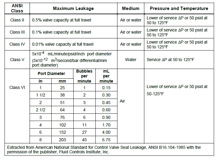
2. For the allowable test leakage rates, refer to FCI-70-2 ( Valve Seat Leakage Class ANSI FCI 70-2 B16.104 ) table below.
3. Calculate Cv at shutoff from the table.
4. For non-compressible fluids, using actual values of DP shutoff and specific gravity, calculate installed allowable leakage rate using the basic sizing equation.
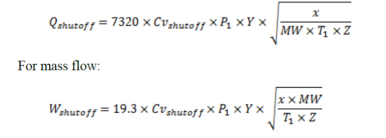
5. For compressible fluids, using actual values of DP, P1, MW, Z, T1, calculate installed allowable leakage rate.
For volumetric flow:
6. Compare the installed allowable leakage rate from step (4) or (5) with the actual flow from step (1) to verify leakage rate.
Control Valve Problems
Example 1
Given:
Actual leakage flow rate = 0.1 gpm
Valve rated Cv = 140
Port diameter = 2.5 IN
Actual DP = 100 psid
Fluid = crude oil (SG = 0.8)
Valve shutoff class = IV
Calculation:
1. Actual leakage flow rate = 0.1 gpm
2. According to FCI 70-2 table, the valve is class IV so allowable leakage is 0.01% of 140
5. (N/A)
6. Since actual leakage flow rate = 0.1 gpm < allowable leakage = 0.1565, then, the valve meets the shutoff class.
Example 2
Given:
Actual leakage flow rate = 0.001 scfm
Valve rated Cv = 25
Xt=0.75
Port diameter = 1 IN
P1= 500 psig
P2= 200 psig
Actual DP = 300 psid
Fluid = Natural Gas (MW = 20)
Valve shutoff class = V
Temperature = 212 F
Z=0.9
k=1.2
Calculation:
1. Actual leakage flow rate = 0.001 scfm
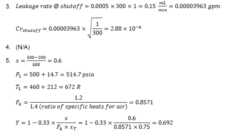
2. According to FCI 70-2 table, class V so allowable leakage is 0.0005 mL per minute per psid per IN of port diameter.
6. Since actual leakage flow rate = 0.001 scfm > allowable leakage = 0.0529 scfh = 0.0008816 scfm, then, the valve does not meet the shutoff class.
CONTROL VALVES EXPLANATION AND ITS TYPES
Valve Quality Inspection Levels & Control Valve Testing
Main keywords for this article are Troubleshooting Control Valve Seat Leakage, Control Valve Seat Leakage Test Procedure, Control Valve Problems, Control Valve Leak Test Procedure,Valve Troubleshooting.


