The article is Advanced Metering Infrastructure System Architecture, AMI Applications Layers, Home Area Network, Neighborhood Area Network, Wide Area Network.
Advanced Metering Infrastructure System Architecture
An AMI Advanced Metering Infrastructure is characterized by two-way communications as opposed to older Automated Meter Reading (AMR) systems from which the concept of AMI and smart metering has evolved. This section aims to describe generic system architecture for AMI, through which a system capable of incorporating all the functions specified in §3 can be developed.
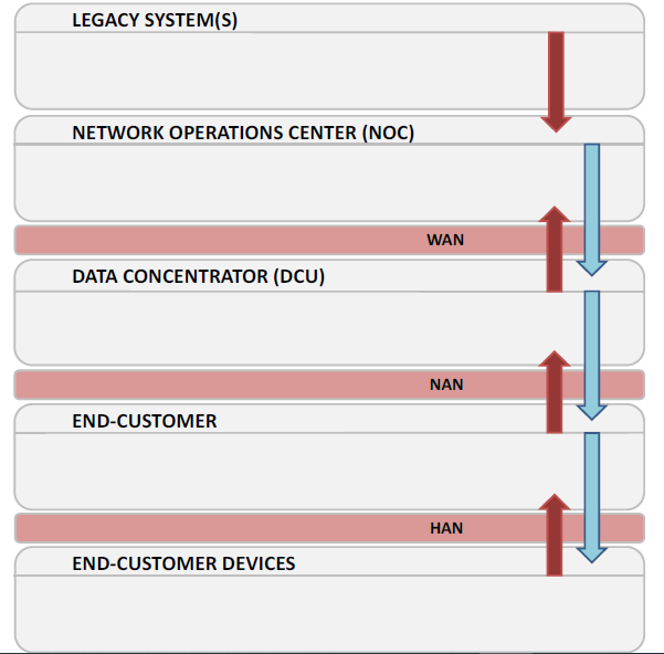
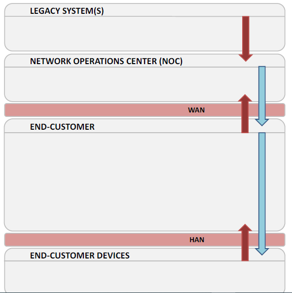
The generally accepted, high-level view of an AMI is captured across two potential topologies (Solutions A and B) within Figure 1 and Figure 2.
These topologies adhere to the general in-Kingdom direction for AMI, as espoused by ECRA. Together, Figure 1 and Figure 2 offer a future-proof model upon which any imminent or future AMI rollouts may be referenced.

Figure 1 – Generic AMI Architecture, System Layers and Interfaces (Solution A)
Figure 2 – Generic AMI Architecture, System Layers and Interfaces (Solution B)
Both Figure 1 and Figure 2 show that the System Architecture of Advanced Metering Infrastructure consists of several Applications Layers, which are interconnected by one of several Communications Layers:
Wide Area Network (WAN), Neighborhood Area Network (NAN) (Solution A only) and Home Area Network (HAN).
The flow of metered data between each Application Layer is also shown. Each of these layers is described in more detail within §4.1 and §4.2.
This article specifies that only one of two similar solutions (denoted A and B) may be pursued when implementing an AMI, whereby for smaller roll-outs the Data Concentration (DCU) layer can be discarded (Figure 2) so that the NOC communicates
directly with the End-Customers across the WAN.
1. AMI Applications Layers
In this section a brief description of each of the functional blocks within the AMI is given. A bottom-up approach is taken to reflect the nature in which metered data typically flows.
1.1 End-Customer Devices
Smart devices within the domain of each End-Customer shall be accessible from the AMI. Energy consumption data can be obtained from each device and the data transferred upwards to the Utility (Figure 1, Figure 2).
Each smart device shall also be capable of receiving set-point commands (either instantaneous or scheduled) from the main element of control within the End-Customer premises. Smart devices exchange data with the main smart meter within an End-Customer Unit, via a communications gateway (if required), across the Home Area Network (HAN) Communications Layer.
1.2 End-Customer
Different types of End-Customer exist, referring to locations such as (but not limited to) the following: Domestic, Municipal Buildings, EV Charging Stations, etc. Each of these metering applications has its own distinct set of sub-functions, to be facilitated within its own metered domain.
For the purposes of specifying an AMI, an End-Customer unit is characterized by the presence of a single interface (for both control and metered data flows) to the wider NAN (Solution A) or WAN (Solution B) through which it supplies metered data information to the utility and/or receives commands from elsewhere in the AMI.
This interface will be facilitated by a smart meter and the data exchange format is common across each End-Customer class in the AMI, i.e., Common Information Model (CIM).
It is possible that more than one meter may exist within an End-Customer instance (especially in the case of Municipal applications). Only one such meter within the End-Customer domain is designated to host the interface to the wider NAN; this meter shall be referred to as the Master End-Customer Meter (MECM) throughout the remainder of this document. Each End-Customer has a single, defined MECM.
Collectively, each End-Customer unit shall incorporate memory and communications processing capabilities for the storage and transmission of data received from any sub-meters, and/or meters used to measure non-electrical consumption data (e.g., water or gas).
The MECM local to the End-Customer shall co-ordinate communications between various distributed elements (e.g., sub-metering instances, smart plugs, etc.) within its dedicated Home Area Network (HAN) layer, if present. This is achieved and any additional protocol conversion performed through a gateway module within the HAN.
Ultimately, the End-Customer unit is remotely managed by the Network Operations Center (NOC), either directly through a communications interface to the WAN (Solution B) or indirectly via a NAN and local Data Concentrator (Solution A).
1.3 Data Concentrator (DCU)
The Data Concentrator unit (DCU) is an intermediate Application Layer between End-Customers and the Network Operation Center (NOC). Its main purpose is to collect and manage the information received from the End-Customers, directly, and indirectly from any multi-utility, sub-meters or End-Customer Devices (embedded within the End-Customer Unit), if present.
An intermediate data collection stage (common terminologies used are collector, aggregator and concentrator) is common to many large scale AMI concepts, especially where PLC technology is used.
For GSM/GPRS based implementations metering equipment can communicate directly with the NOC Application Layer. Irrespective of the architecture chosen it shall adhere to either Solution A (Figure 1) or Solution B (Figure 2).
For Solution A, metered data (measurements, alarms, etc.) is sent to the NOC, via the DCU Application Layer, across the WAN Communications Layer. For control actions (commands, programming, reconfigurations, etc.), data flows in the opposite direction; from the NOC to the MECMs, via the DCU and across the WAN and NAN Communications layers.
The DCU acts to safeguard the data privacy of residents (Domestic End-Customers) participating within the AMI. The DCU also shall facilitate secure, direct, local access, for O&M purposes.
In the case, given the relatively high density of Distribution Transformers (DTs) within its residential communities, it is anticipated that the DCUs will be placed on the secondary side of selected DTs and so each DCU will handle a relatively small amount of residential data.
The presence of the DCU Application Layer means that WAN communications do not have to be extended to the End-Customer layer. This will yield benefits both in terms of lower bandwidth utilization rates and reduced installation costs for the AMI (as relatively inexpensive PLC communications can be used across the NAN).
1.4. Network Operations Center (NOC)
The Network Operation Center (NOC) layer for the metering system is a collective name given to the hardware hosted at the substation, or across multiple corporate entities within the utility’s premises, required to collect all the metered data received from the field. The NOC also accommodates various software applications through which data monitoring and analytical tasks may be performed.
Typically, the hardware deployed at the NOC may consist of a Head End System (HES), used to receive metered data directly from the WAN; a single Meter Data Management (MDM) system; a separate Data Historian (if required), any Remote Terminal Units (RTUs) used to poll DCUs, or collect data, and any supplementary backend data analytics.
The NOC is responsible for the management of all alarms, data and events related to smart metering, as well as the configuration, monitoring, control and operation of all system components. These functions are enacted via the interface between the NOC and the WAN Communications Layer (§4.2.3). The NOC also interfaces with Legacy Systems (i.e., those existing pre-AMI), e.g., the Saudi Aramco’s Enterprise Software system, for functions such as billing.
The NOC may receive orders from a Legacy System and so has to ensure that these are executed correctly and in a timely manner, the NOC will also return any result of such operations to the Legacy System.
Legacy System-to-NOC instructions may include the reading of different parameters, reconfiguration of field components, remote disconnection of supply, etc. The NOC might delegate parts of its operation to the DCU layer, if present (Solution A), such that certain operations can be performed locally without the need for continuous wide-area communications (preserving bandwidth in the WAN layer).
A single HES should be chosen for the AMI that is disassociated with the vendor chosen to provide smart meters within the same system. It must be inter-operable with the single MDM unit chosen for the AMI.
By adopting standardized OBIS codes (in line with those published within the Industry Standards of Table 2), potential exists for different metering vendors (each of which is DLMS/COSEM-compliant and adopts a uniform OBIS code) and/or topologies to be used in parallel within the same AMI, despite the presence of only one MDM and one HES.
1.5 Legacy Systems
These are existing enterprise systems that manage business processes of the utility. These systems do not communicate directly with the AMI devices in the field but provide and receive data from the NOC Application layer.
2. Communications Layers
In this section a brief description of each of the Communication Layers, which host the interfaces between the functional AMI blocks specified in §4.1, are introduced. Once more, a bottom-up approach is taken to reflect the nature in which metered data typically flows.
2.1 Home Area Network (HAN)
HANs are the local means for automation and monitoring within the boundaries of a single End-Customer Unit. They facilitate all communications (e.g., scheduling information and active set-point control) between enabled devices, such as smart thermostats, smart plugs and smart appliances and the smart meter, via the in-home gateway.
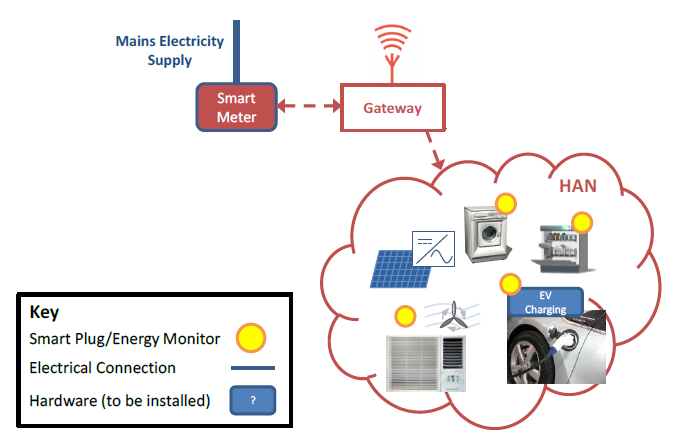
A conceptual view of devices that may fall under the control of the HAN within a future “smart home” is shown in Figure 3.
Communications hubs, or gateways, may be required within “smart homes” so that distributed control of addressable elements can be performed and the contribution of each item to the total metered load of the home can be quantified. Gateways act as the interface between the HAN and the MECM.
The gateway provides the communications interface between the smart meter and monitored/controllable appliances such as fridge-freezers, washing machines, dish-washers and driers. The gateway enacts all necessary protocol conversion between the smart meter and the native HAN-level protocol of the appliances.
2.2 Neighborhood Area Network (NAN)
Should Solution A (Figure 1) be adopted by any company, a philosophy where smart meters collect data locally and transmit, via a NAN, to a data collector shall be followed. From a metering perspective, a NAN facilitates the transfer of data from multiple (at least one) End-Customer(s) to a single DCU unit in the Data Concentrator Application Layer (§4.1.3).
It is important to distinguish between NANs, of which there may be several, and the WAN (§4.2.3) of which there is only one. This distinction renders Solution A to be more scalable than if a single, unified communications network (from smart meter-to-substation) was implemented (Solution B).
For example, the future integration of ten new homes to the AMI may only require a single new communication channel to be added (plus a new NAN and associated DCU) within the WAN, rather than ten new WAN connections, one for each MECM.
The differentiation of the NAN and WAN layers helps to preserve wide-area bandwidth, as the number of point-to-point communication links within the WAN is reduced if the NAN layer is utilized (Solution A).
Vertical sectionalizing of the communications infrastructure and the extra layers of hierarchy it implies ensures that the data privacy of home users can be safeguarded as the direct transfer of data from home to utility is avoided.
2.3 Wide Area Network (WAN)
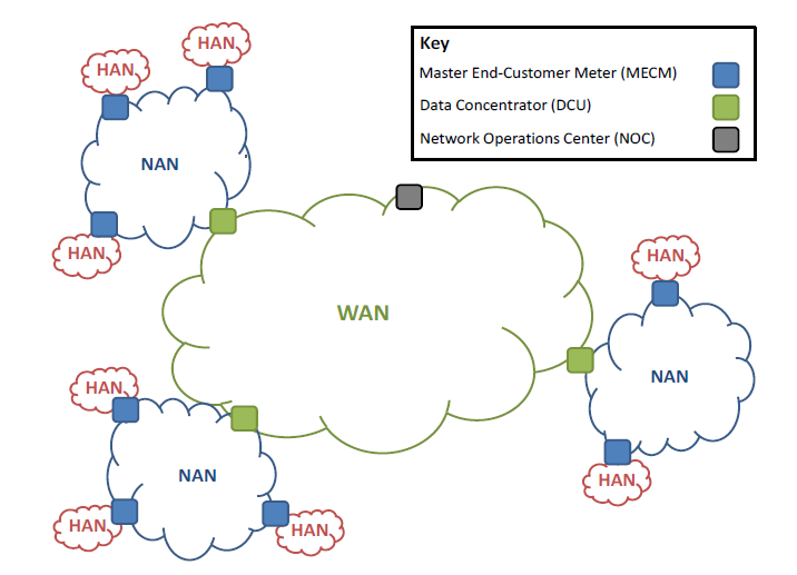
An overview of the partitioning of the AMI communications is made, as per Figure 4.
The WAN (also known as the Backhaul Network) hosts the communications between the substation and the DCUs. There is only one WAN, whereas several NAN instances (sub-DCU layer) may exist.
The protocols and medium of communication may differ within the WAN in comparison to that deployed within the NANs.
For the WAN functional block no preference is given to wired or wireless communications, although the vendor must ensure that any wireless communications comply with licensing regulations, as prescribed by the Communications and Information Technology Commission (CITC), see Appendix A.
Thus, in practical terms only GSM/GPRS or VSAT based WAN communications are acceptable.
Above we have discussed all these topics Advanced Metering Infrastructure System Architecture, AMI Applications Layers, Home Area Network, Neighborhood Area Network, Wide Area Network.
All article related to Smart Metering Technology are linked below step by step.
Advanced Metering Infrastructure | Smart Metering Technology
Advanced Metering Infrastructure Functionality – AMI Functions
Advanced Metering Infrastructure System Design Architecture
Advanced Metering Infrastructure Components
Advanced Metering Infrastructure Functional Requirements
Domestic Smart Meter Installation – ANSI 12.20 Electricity Meters
Data Concentrator Unit | DCU Principle with Technical Specification
Head End System for Advance Metering Infrastructure


