Air foil shapes, also known as wing profiles or wing sections, are designed to generate lift when air flows over them. These shapes are crucial components of aircraft wings, propeller blades, and wind turbine blades. Air foil shapes are characterized by their cross-sectional geometry, which includes features such as camber, thickness, and curvature.
What are Air Foil Shapes?
The geometric figure obtained as a cross-section of an airplane wing is referred to as an air foil. When an air foil-shaped body moves through a fluid, it produces aerodynamic forces. The force perpendicular to the direction of motion is called lift, while the force parallel to the direction of motion is called drag. To calculate the movement of an airplane accurately, it’s crucial to determine the forces and torques around the center of gravity caused by the effects of air.
The aerodynamic forces involved are:
- Lift (L): The force generated perpendicular to the direction of motion. Lift is what keeps the airplane airborne and opposes the force of gravity.
- Drag (D): The force acting parallel to the direction of motion. Drag opposes the motion of the airplane through the air and is caused by air resistance.
- Lateral Force (Q): The sideways force acting perpendicular to both lift and drag. It affects the sideways movement or stability of the aircraft.
The aerodynamic torques involved are:
- Roll Torque (Mx): The torque causing the airplane to rotate around its longitudinal axis. It influences the roll motion of the aircraft, which is the rotation about the wings.
- Pitch Torque (My): The torque causing the airplane to rotate around its lateral axis. It affects the pitch motion, which is the rotation about the axis parallel to the wings.
- Yaw Torque (Mz): The torque causing the airplane to rotate around its vertical axis. It influences the yaw motion, which is the rotation about the vertical axis perpendicular to the wings.
Understanding these aerodynamic forces and torques is essential for analyzing and predicting the behavior of an aircraft in flight. They play a critical role in flight control, stability, and maneuverability.
Air foil nomenclature
The nomenclature and description of air foils involve several key terms and concepts:
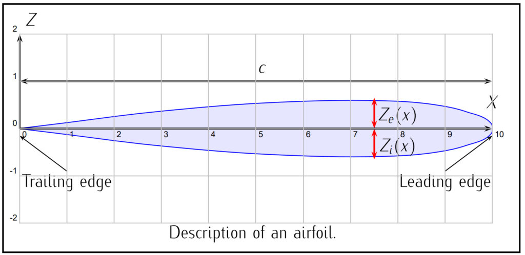
- Chord (c): The chord is the straight line segment that connects the leading edge (xle) to the trailing edge (xte) of the air foil.
- Extrados (ze(x)) and Intrados (zi(x)): These terms refer to the upper and lower surfaces of the airfoil, respectively. They are described by functions that define their shapes along the chord length (x).
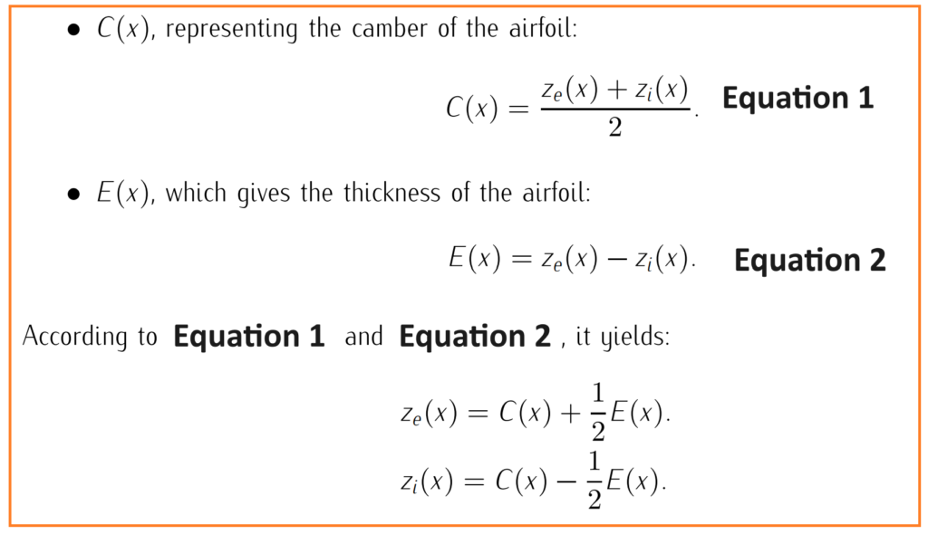
- Camber (C(x)): Camber represents the curvature of the air foil. It is calculated as the average of the extrados and intrados shapes.
- Thickness (E(x)): Thickness describes the distance between the extrados and intrados at a given point along the chord. It characterizes the thickness of the airfoil section.
- Symmetric Air foil: An airfoil is symmetric if its camber is zero at all points along the chord.
- Relative Thickness: The relative thickness of an airfoil is the ratio of its thickness to its camber, usually expressed as a percentage.
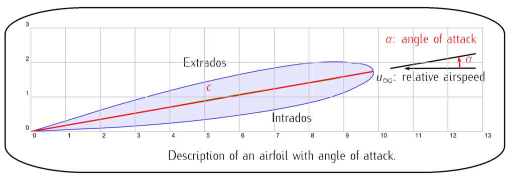
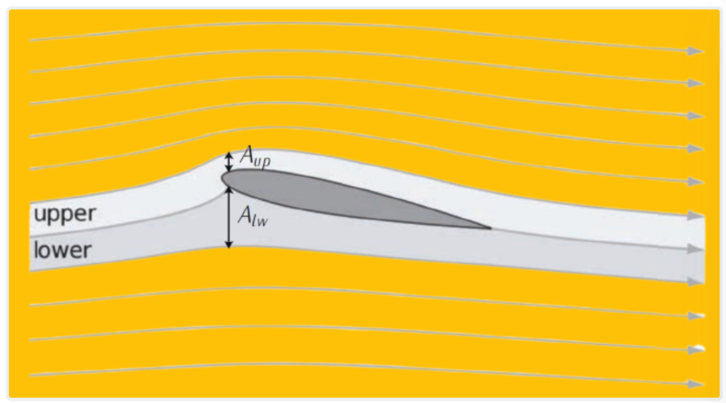
- Angle of Attack (α): The angle of attack is the angle between the direction of the incoming air flow (undisturbed flow) and the chord line of the air foil. It affects lift and drag generation.
Mathematical relationships between these parameters are described by equations such as:
- Angle of Attack (α): The angle formed by the undisturbed air flow direction and the chord line.
Additionally, to give an angle of attack to the air foil, a rotation is applied around an arbitrary point x0. This rotation is approximated by adding a linear term proportional to the angle of attack to both the extrados and intrados functions.

This breakdown of the air foil into camber, thickness, and angle of attack components helps in analyzing the contributions of each factor to the aerodynamic performance, particularly lift generation.
Aerodynamic Forces Generations
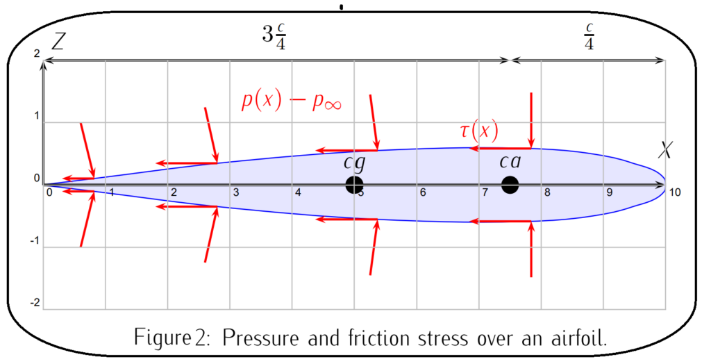
The generation of aerodynamic forces on a body moving through air involves two main factors: pressure distribution and shear stress distribution over the body’s surface.
- Pressure Distribution:
- The movement of the body through air creates variations in air pressure around its surface.
- At each point on the body’s surface, there is a perpendicular stress caused by this pressure difference.
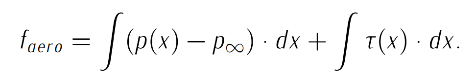
- Integrating the pressure distribution over the entire surface of the body yields the total aerodynamic force.
- Shear Stress Distribution:
- Additionally, the air flowing past the body creates shear stress tangent to the surface due to viscosity.
- This shear stress distribution is also integrated over the body’s surface to calculate its contribution to the aerodynamic force.
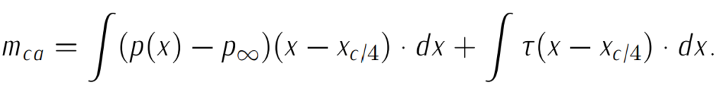
The total aerodynamic force, denoted as Faero, is obtained by adding the integrated pressure difference (p(x)−p∞) and the integrated shear stress τ(x) over the body’s surface, as shown in Equation below.
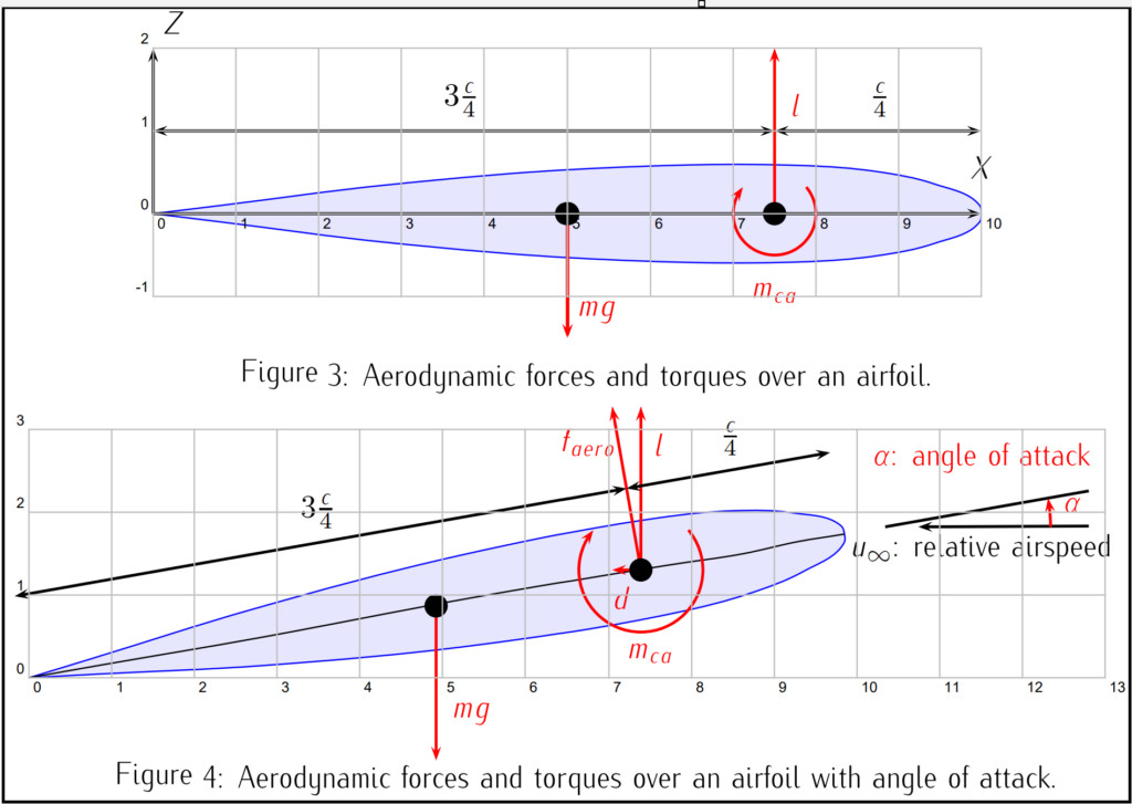
Furthermore, aerodynamic torques, denoted as mca, can be calculated by taking the resultant of the pressure and shear stress distributions and multiplying by the distance to a fixed point, typically the aerodynamic center c/4 of the body. This is illustrated in Equation below.
These equations allow engineers to analyze and predict the aerodynamic behavior of bodies moving through air, helping in the design and optimization of various aerodynamic structures and vehicles. Figure 2, Figure 3, and Figure 4 visually represent these concepts.
In an air foil, lift primarily arises from pressure forces, while drag results from both friction (shear stress) and pressure forces.
Drag Forces:
- Drag is influenced by the thickness of the boundary layer – a thin layer of air adjacent to the air foil’s surface.
- A thicker boundary layer increases drag, especially when the airflow becomes turbulent, causing a significant rise in pressure drag.
- Friction forces are greater in turbulent flow compared to laminar flow, but their contribution to drag is usually lower than that of pressure forces.
- Therefore, optimizing the air foil design to manage the boundary layer behavior is important for minimizing drag.
Lift Forces:
- Lift is generated by the shape of the air foil, influenced by its camber, angle of attack, and thickness.
- The air foil’s shape results in lower pressures on the extrados (upper surface) compared to the intrados (lower surface), creating lift.
- This lift generation process can be explained as follows:
- According to the law of mass continuity, airflow velocity increases over the top surface of the air foil more than over the bottom surface.
- Due to the Bernoulli effect, which relates pressure and velocity, the pressure over the top surface becomes lower than over the bottom surface.
- This pressure difference results in an upward lift force on the air foil.
While this simplified explanation provides a qualitative understanding of aerodynamic forces, the actual resolution of fluid mechanics equations (Navier-Stokes equations) is extremely challenging. Therefore, theoretical studies often use simplifications, while experimental approaches involve testing scale models in wind tunnels – a controlled environment for studying airflow.